Language selection

Search

Patent 2412261 Summary

Third-party information liability

Some of the information on this Web page has been provided by external sources. The Government of Canada is not responsible for the accuracy, reliability or currency of the information supplied by external sources. Users wishing to rely upon this information should consult directly with the source of the information. Content provided by external sources is not subject to official languages, privacy and accessibility requirements.

Claims and Abstract availability

Any discrepancies in the text and image of the Claims and Abstract are due to differing posting times. Text of the Claims and Abstract are posted:

  • At the time the application is open to public inspection;
  • At the time of issue of the patent (grant).
(12) Patent: (11) CA 2412261
(54) English Title: SECURING DEVICE INVOLVING A PISTON PROPELLED BY COMPRESSED GAS
(54) French Title: DISPOSITIF DE FIXATION COMPORTANT UN PISTON POUSSE PAR GAZ COMPRIME
Status: Deemed expired
Bibliographic Data
(51) International Patent Classification (IPC):
  • F41A 21/28 (2006.01)
  • B25C 1/08 (2006.01)
(72) Inventors :
  • TOULOUSE, BRUNO (France)
(73) Owners :
  • SOCIETE DE PROSPECTION ET D'INVENTIONS TECHNIQUES S.P.I.T. (France)
(71) Applicants :
  • SOCIETE DE PROSPECTION ET D'INVENTIONS TECHNIQUES S.P.I.T. (France)
(74) Agent: FINLAYSON & SINGLEHURST
(74) Associate agent:
(45) Issued: 2005-06-14
(22) Filed Date: 2002-11-20
(41) Open to Public Inspection: 2003-05-21
Examination requested: 2002-11-20
Availability of licence: N/A
(25) Language of filing: English

Patent Cooperation Treaty (PCT): No

(30) Application Priority Data:
Application No. Country/Territory Date
01 15052 France 2001-11-21

Abstracts

English Abstract

The device for securing a plug, of the type involving a piston (9) propelled by gas, comprises a combustion chamber (5) delimited on one side by the piston and on the other side by a cylinder head (7) with a duct (19) for injecting combustible gas open via one end (19A) into the chamber. According to the invention, the duct (19) comprises a means for creating a pressure drop between the part of the duct (19) upstream of the said end (19A) and the chamber (5) itself, so as to at least partially avoid the vaporizing of the combustible gas in the said part of the duct upstream of the end.


French Abstract

Dispositif de fixation de tampon, du type impliquant un piston (9) propulsé par un gaz, comprenant une chambre de combustion (5) délimitée d'un côté par le piston et de l'autre par une culasse (7) avec une conduite (19) pour l'injection de gaz combustible, débouchant par une extrémité (19A) dans la chambre. Selon l'invention, la conduite (19) comprend un moyen permettant de créer une chute de pression entre la partie de la conduite (19) en amont de ladite extrémité (19A) et la chambre (5) elle-même, de façon à éviter au moins partiellement la vaporisation du gaz combustible dans ladite partie de la conduite en amont de l'extrémité.

Claims

Note: Claims are shown in the official language in which they were submitted.


-5-
WHAT IS CLAIMED IS:
1. Device for securing a plug, of the type involving
a piston (9) propelled by gas, comprising a
combustion chamber (5) delimited on one side by
the piston and on the other side by a cylinder
head (7) with a duct (19) for injecting
combustible gas open via one end (19A) into the
chamber, characterized in that the duct (19)
comprises at least a lateral orifice (192) near
its end (19A) with a narrowed section creating a
pressure drop between the part of the duct (19)
upstream of the said end (19A) and the chamber (5)
itself, so as to at least partially avoid the
vaporizing of the combustible gas in the said part
of the duct upstream of the end.
2. Device according to the claim 1, the duct
comprising an axial orifice (191) at its end.
3. Device according to one of the preceding claim 1
or 2, the cross section of the orifice or of the
orifices being at least 10% smaller than the cross
section of the duct.
4. Device according to claims 1, 2 or 3, comprising a
blower for mixing inside the combustion chamber,
the duct comprising at least one orifice oriented
in such a way as to direct at least some of the
combustible gases injected into the chamber toward
the blower (15).
5. Device according to the preceding claim,
comprising a second orifice directing some of the
combustible gases in a direction parallel to the
plane of the piston (9).

Description

Note: Descriptions are shown in the official language in which they were submitted.


CA 02412261 2002-11-20
- 1 -
SECURING DEVICE INVOLVING A PISTON
PROPELLED BY COMPRESSED GAS
The invention relates to a device for securing a plug
with a motor involving a piston propelled by gas,
particularly combustion gases. It is aimed in
particular at a means improving the combustion inside
the chamber in which the gases are produced.
A device of this type comprises a casing which has the
overall farm of a gun. This casing contains a small
znternal combustion engine which drives a plug guide in
to a translation movement. The plug guide is secured to a
piston propelled by a compressed gas which is the
product of the combustion of a combustible gas in the
adjoinizlg combustion chamber. The gaseous mixture
comprising the air and the combustible gas is created
in the chamber then ignited by an appropriate ignition.
means. The gun comprises a. combustible-gas cartridge
housed, for example, in the hand grip. then a plug is
fired, a metered amount of combustible gas zs sent into
the chamber, then voltage is app~_ied to the firing
means. In devices known to the applicant company, the
gas follows a path along t:he device from a metering
valve near the gas cartridge to the combustion chamber.
The gas is gu~.ded along a duct, generally a fine tube,
arranged between the valve and the chamber_
With the devices found on the marker, it is observed
that there is a significant delay between the time of
firing and the actual ejection of the plug. This delay
may prove troublesome when the operator is in an
3o uncomfortable position and the device is li7cely to
move.
The applicant company has set. its sights on reducing
this reaction time as far as possible.
According to the invention, this result is achieved by
incorporating a means that creates a pressure drop
between the part of the tube upstream of its end near
the combustion chamber and t:he chamber itself, so as to

CA 02412261 2002-11-20
at least partially avoid the vaporizing of the gas
upstream o~ the said end.
Such a means consists o~ a narrowing of the tube at its
end, the tube has a side orifice.
What happens is that the gas is normally in the liquid
state in the cartridge, and experiences expansion as it
leaves the metering valve. It has been obsex-ved that,
surprisingly, if the time of its vaporization prior to
entering the chamber is delayed, the time that the
device takes to react the squeezing of the trigger is
reduced.
~.5 This result can be explained by the fact that there is
a link between the vaporizing of the gas as it passes
through the metered valve, and the time taken to fill
the combustion chamber. With devices of the prior art,
the time is relatively long. By contrast, with the
solution of the invention, the gas is propelled in
greater quantity and in a shorter time because it
remains partially in the liquid state immediately
upstream of the atomization orifice. The cycle time is
thus reduced.
Accozdiz~.g to another characteristic, the cross section
of the orifice or of the orifices is at least IO% less
than the cross section of the duct.
Other characteristics and advantages of the invention,
will become apparent from reading the description which
follows, which relates to one particular embodiment of
a device, with reference to the appended drawings in
which
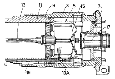
Figure 1 depicts a 'part view in axial section of the
device
Figure 2 shows one example of the end o~ the chamber
supply tube.

CA 02412261 2002-11-20
- 3 -
Figure 1 shows the rear end of the devzce 1 without its
case_ The sleeve 3 of the combustion. chamber 5, closed
by a cylinder head 7 on one side and by a piston 9 on
the other side may be seen. The piston s moves in
translation in a cylinder 11 and is secured to a rod
13. Th~.s rod rests at its other end, not depicted,
against a plug that is to be propelled. A blower 15 is
mounted inside the chamber 5 and its function is to
activate the mixing of the gases- It is driven by a
motor 1? housed in the cylinder head 7. zts axis of
rotation here lies in the continuation of the rod 13.
The gaseous mixture is ignited by a means which has not
been depicted and which lies in the region of the
cylinder head, behind the blower.
A gas inj action tube or duct opens into the combustion
chamber. Its axis ~.s roughly parallel to that of the
rod 13. It is connected at its other end, not visible
in the figure, to the metering valve. The latter is
arranged in a housing of the device which is designed
fox that purpose.
Figure 2 depicts an embodimezxt of the end 19A of the
injection Cube. This end shows an axial first orifice
191 which allows injection in the continuation of the
duct 19 towards the blades of the blower. xt also
comprises an orifice 1.92. This orifice is placed on the
wall of the tube 19 for radial. injection parallel to
the plane of the piston 9. According to the invention,
the total. of .the cross sections of the orifices is less
than the cross section of the tube, so as to create a
pressure drop between the tube and the combustion
chamber_
According to another embodiment, the tube is closed at
its end via a transverse wall and has only openings
made in the wall, laterally.

CA 02412261 2002-11-20
- 4 -
A tube according to the invention was made and used to
replace the tube of ari existing device.
The characteristic dimensions were as follows:
Izlternal cross section of the tube : 1 . 00 units
(of area) .
Cross section of the axial circular orifice:
0_35 unit.
Cross section of the lateral circular orifice:
0.50 unit.
The narrowing of the cross section of the duct was
therefore 15~.
Comparative tests were carried out comparing the
solution of the invention with that of the prior art_
It was found that it was thus possible to increase for
a firing rate of one shot per second to two shots per
second without making any other modificatioz~s.

Representative Drawing
A single figure which represents the drawing illustrating the invention.
Administrative Status

For a clearer understanding of the status of the application/patent presented on this page, the site Disclaimer , as well as the definitions for Patent , Administrative Status , Maintenance Fee  and Payment History  should be consulted.

Administrative Status

Title Date
Forecasted Issue Date 2005-06-14
(22) Filed 2002-11-20
Examination Requested 2002-11-20
(41) Open to Public Inspection 2003-05-21
(45) Issued 2005-06-14
Deemed Expired 2017-11-20

Abandonment History

There is no abandonment history.

Payment History

Fee Type Anniversary Year Due Date Amount Paid Paid Date
Request for Examination $400.00 2002-11-20
Registration of a document - section 124 $100.00 2002-11-20
Application Fee $300.00 2002-11-20
Maintenance Fee - Application - New Act 2 2004-11-22 $100.00 2004-11-08
Final Fee $300.00 2005-03-29
Maintenance Fee - Patent - New Act 3 2005-11-21 $100.00 2005-11-02
Maintenance Fee - Patent - New Act 4 2006-11-20 $100.00 2006-10-30
Maintenance Fee - Patent - New Act 5 2007-11-20 $200.00 2007-10-30
Maintenance Fee - Patent - New Act 6 2008-11-20 $200.00 2008-10-30
Maintenance Fee - Patent - New Act 7 2009-11-20 $200.00 2009-10-30
Maintenance Fee - Patent - New Act 8 2010-11-22 $200.00 2010-11-01
Maintenance Fee - Patent - New Act 9 2011-11-21 $200.00 2011-10-31
Maintenance Fee - Patent - New Act 10 2012-11-20 $250.00 2012-10-29
Maintenance Fee - Patent - New Act 11 2013-11-20 $250.00 2013-10-30
Maintenance Fee - Patent - New Act 12 2014-11-20 $250.00 2014-11-17
Maintenance Fee - Patent - New Act 13 2015-11-20 $250.00 2015-11-16
Owners on Record

Note: Records showing the ownership history in alphabetical order.

Current Owners on Record
SOCIETE DE PROSPECTION ET D'INVENTIONS TECHNIQUES S.P.I.T.
Past Owners on Record
TOULOUSE, BRUNO
Past Owners that do not appear in the "Owners on Record" listing will appear in other documentation within the application.
Documents

To view selected files, please enter reCAPTCHA code :


To view images, click a link in the Document Description column. To download the documents, select one or more checkboxes in the first column and then click the "Download Selected in PDF format (Zip Archive)" or the "Download Selected as Single PDF" button.

List of published and non-published patent-specific documents on the CPD .

If you have any difficulty accessing content, you can call the Client Service Centre at 1-866-997-1936 or send them an e-mail at CIPO Client Service Centre.


Document
Description 
Date
(yyyy-mm-dd) 
Number of pages   Size of Image (KB) 
Abstract 2002-11-20 1 19
Description 2002-11-20 4 153
Claims 2002-11-20 1 37
Drawings 2002-11-20 1 33
Representative Drawing 2003-02-10 1 25
Cover Page 2003-04-25 1 54
Cover Page 2005-05-19 1 54
Correspondence 2005-03-29 1 31
Assignment 2002-11-20 4 149
Prosecution-Amendment 2003-12-30 1 29
Assignment 2014-04-15 45 2,993
Assignment 2015-10-02 14 524
Office Letter 2015-10-22 1 34