Note: Descriptions are shown in the official language in which they were submitted.
CA 02412314 2002-12-05
THROW SHOE FOR CENTRIFUGAL-TYPE CRUSHERS
WITH A VERTICAL SHAFT AND METHOD OF PRODUCTION
Object of the invention
[0001] The present invention relates to a throw shoe
(also called impacter or impeller), which is intended for
so-called VSI-crushers (Vertical Shaft Impacter), i.e.
centrifugal-type crushers with a vertical shaft and a
reinforcement structure.
Technological background of the invention
[0002] The aforementioned crushers are well known in the
prior art and widely used for crushing rock aggregates,
among others in quarries and cement works.
[0003] The document WO 99/47264 and other documents
cited in that publication refer to such crushers.
[0004] Those documents indicate that centrifugal-type
crushers comprise a cylindrical housing containing a
rotary table, which is supported by a vertical bearing
and which comprises means to rotate the table about the
central shaft of the crusher. The crusher comprises a
series of throw shoes or impacters fixed onto the rotary
table, as well as a series of anvils located on the inner
vertical wall of the cylindrical housing, around the
rotary table.
[0005] Throw shoes usually have a parallelepiped shape,
generally made of cast iron and affixed to the rotary
table of the crusher. The side of the throw shoe which is
turned toward the rotation axis of the table is called
CA 02412314 2002-12-05
2
the nose of the throw shoe, while the side which is
parallel to the anvils fixed to the cylindrical housing
forms the exit side of the throw shoe.
[0006] The front side of the throw shoe, called the
working side, is the one encountering the material to be
crushed and preceding the rear side in the rotation
direction of the throw shoe.
[0007] This front working side of the throw shoe may be
provided with one or more cavities, which do not run
through the whole structure of the throw shoe and which
form pockets, these pockets fill up with material when
the crusher is rotating and thus protect the throw shoe
from shocks and erosion due to the material that has
accumulated in the pockets.
[0008] During the crushing operation, the material to be
crushed is poured into the centre of the rotary table by
known means. Due to centrifugal force and to the impact
with the working side, the material is thrown towards the
anvils, against which it is crushed before it drops, in
crushed form, at the bottom of the crusher from where it
is removed. While the material is being thrown, the throw
shoes are subjected to very high stresses and
consequently to rapid wear.
[0009] Thanks to the accumulation of material in the
pockets, the use of pocket throw shoes considerably
increase the working lifetime of the throw shoes in
certain applications.
[0010] In this type of throw shoe, it is observed that
the wear preferentially occurs around the exit edge of
the pockets, i.e. where the abrasion due to the particles
thrown by the centrifugal force is highest.
[0011] The above-mentioned document WO 99/47264 and
other documents therein cited display protections or
reinforcements meant to avoid or reduce such erosion
effects.
CA 02412314 2002-12-05
3
[0012] The specific solution put forward by
WO 99/47264, i.e. the production of a throw shoe with one
or several pocket(s) with an essentially parallelepiped
form, consists in creating on the whole periphery of the
pocket(s)' or on part of said periphery a reinforcement
structure made out of a composite material, obtained from
an iron-based alloy and highly erosion-resistant ceramic
tiles. That structure, which is formed in situ during the
casting of the throw shoe by infiltration of the liquid
metal used to form the body of the piece in a mass of
ceramic tiles and binder, has proved particularly
effective to ensure an increased working lifetime of the
throw shoe.
[0013] Although this type of production provides
considerable technical progress and technological
advantages, some limitations or difficulties have
appeared.
[0014] First of all, the support made out of ceramic
tiles and binder has to be perfectly infiltrated by the
metal in order to obtain effective turnover.
[0015] The width of the metal on either side of the
support should be large enough to ensure sufficient
infiltration of the ceramic component of the
reinforcement structure. Which means that a large width
of the walls of the composite piece must be provided,
which has the consequence of limiting the dimension of
the pockets. Thus, the width of the ceramic reinforcement
also has to be controlled in order to improve the
infiltration; this limitation of the width of the
reinforcement makes it less effective and more fragile.
[0016] Moreover, in the case of throw shoes with one
pocket as well as throw shoes with several pockets, the
pockets are empty when the throw shoes are first used and
unprotected by the material to be crushed.
CA 02412314 2002-12-05
4
[0017] During that first use, the thin walls are
particularly exposed to impacts due to the biggest
aggregates or to alien material (steel pieces, shovel
teeth, etc.).
[0018] This can lead to the breaking of the most fragile
reinforced walls, which seriously damages the piece and
often requires its replacement very soon after the first
use.
(0019] In the case of crushers with a vertical shaft,
the wear profile is generally hard to control because the
working conditions depend on different parameters, which
change with time: supplying particle size, aggregate
abrasiveness, etc.
[0020] With the solution disclosed in WO 99/47264, a
change in the form of the pockets induces a complete
change of the cast models and pit boxes, with no
possibility to predict the obtained result.
[0021] Moreover, these operations are very expensive
and result in important time losses.
[0022] Furthermore, when the profile of the pockets
has to be changed, there is also a limitation in the form
because of the above-mentioned infiltration difficulty.
[0023] Finally, the wear of throw shoes in
VSI-crushers is all the same a major problem because the
abrasion and shocks are excessively severe. To increase
the working lifetime of the throw shoes is a constant
concern.
Object of the invention
[0024] The invention aims to solve the above-mentioned
problems, and in particular to further improve the
performances of throw shoes by making the most of the
inner advantages of the throw shoes production technology
described in WO 99/47264.
CA 02412314 2002-12-05
Summary of the invention
[0025] The invention proposes a throw shoe intended for
centrifugal-type crushers with a vertical shaft, which
unlike the ones disclosed in the aforementioned prior
art,'does not deliberately and initially, i.e. when first
used, comprise cavities or pockets, but which comprises
on its working side a composite reinforcement structure
obtained from an iron-based alloy and highly wear-
resistant ceramic tiles, said composite reinforcement
structure being formed in situ during the casting of the
throw shoe by infiltration of the liquid metal used to
form the body of the piece in a mass of ceramic tiles and
binder.
[0026] Said reinforcement structure is provided on the
working side according to a suitable geometrical
disposition in order to let the metal locally (i.e. in
the zones without reinforcement structure) show on the
working surface, so that the working wear automatically
results in the formation of pockets or cavities, which
exert a protection function against shocks by filling up
with crushed material, while at the same time maintaining
the reinforcement structure at the upper periphery of the
pockets thus formed, i.e. on the working surface.
[0027] The throw shoe thus produced can entirely solve
the aforementioned problems.
[0028] As far as the infiltration difficulties are
concerned, the quantity of metal available to infiltrate
the support is according to the invention all the metal
constituting the piece, instead of only the metal
constituting a single wall. Moreover, a larger
reinforcement can be introduced where it is judged
necessary, because the infiltration conditions are
enhanced due to the bigger mass of liquid metal.
[0029] The fact that the pockets are not formed from the
start totally avoids the risk due to the presence of thin
CA 02412314 2002-12-05
6
walls during the first use, because large enough walls
can be produced.
[0030] In the embodiment according to the invention,
only the profile of the reinforcement has to be changed
if the form'of the pockets needs to be changed, which
highly lowers the costs and furthermore offers better
possibilities of form and conception. Moreover, it is
possible to cast the piece without using one or more
sandpits in order to form the pocket(s), which
considerably reduces production costs.
[0031] Finally, the technique according to the invention
can noticeably increase the working lifetime because as
soon as the pockets start to form, autoprotection occurs
due to the material retained in the pockets being formed.
The process of the formation of the pockets is slowed
down and when they are fully formed, all the time needed
for the formation has saved up working lifetime.
[0032] As a summary, the invention integrates all the
specific advantages described in WO 99/47264 of a
reinforcement structure, made out of a composite material
and formed in situ by infiltration of a liquid metal in a
ceramic mass with the ease and advantages of the
production of a piece, with no obligation to provide one
or several pocket(s).
[0033] The process used is particularly simple to
carry out, it simply consists in fixing a ceramic wear-
resistant cover, preferably in the form of a mass of a
binder and ceramic tiles from alumina and zirconia, at
the bottom of a mould by conventional means such as
gluing, mechanical fixing, nails, screws, cramping shaft
or others depending on the desired geometrical
disposition to allow the subsequent formation of one or
several pocket(s) by wear, and then in casting the
metallic mass used to form the body of the throw shoe.
When this metal infiltrates the ceramic mass, it ensures
its perfect connection to the cast piece during the
CA 02412314 2002-12-05
7
cooling of the piece. The piece is then removed from the
mould and, after possible finishing (trimming, etc.), the
throw shoe can be directly used.
[0034] Other characteristics and advantages of the
invention will be clearly understood thanks to the
following description, with reference to the attached
drawings.
Brief description of the drawings
[0035] In the different drawings enclosed herewith,
- Figure 1 is a perspective view of a pocket throw shoe
according to the prior art, with a ceramic
reinforcement infiltrated by metal;
- Figure 2 is a perspective view of a throw shoe without
pockets according to the present invention with the
same kind of reinforcement;
- Figure 3 is a longitudinal section view of a throw
shoe according to Fig. 2 with the evolution line of
the profile of the pockets during their formation.
Detailed description of a preferred embodiment of the
invention
[0036] Identical reference numbers are used in the
different figures for identical or similar constituent
elements.
[0037] A conventional throw shoe 1 according to Fig.l
comprises one or several pocket(s), in this case the cast
pockets 2 and 2', before the throw shoe 1 is used. This
throw shoe advantageously comprises reinforcements 4 in
infiltrated ceramic. The nose 6 of the throw shoe and the
exit side 7 of the throw shoe, which are usually highly
solicited, can comprise additional reinforcements, such
as reinforcement 8 represented on Fig.l.
[0038] In the case of the embodiment represented on
Fig.2, the throw shoe 1 is designed before it is used as
CA 02412314 2002-12-05
8
a full piece, without pockets on its working side 5 but
provided with cast reinforcements 4. These reinforcements
can be arranged, as represented on Fig.2, according to a
form and disposition similar to those provided on Fig.l,
if one wishes to form two pockets in service. Of course,
according to the desired aims, other forms and
dispositions are possible.
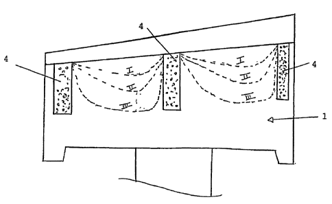
[0039] Fig.3 shows the evolution in service
(Progression I, II and III) of the profile of the pocket
being formed, due to the presence of the reinforcements 4
before the piece is first used.
[0040] The middle reinforcement, which separates the
pockets 2 and 2' and which is shared by them, is
represented on Fig.l as presenting the same width as the
corresponding middle reinforcement of Fig.2 (and Fig.3).
In the case of the embodiment of Fig.1, the width is
however limited because it is particularly difficult in
this case to totally infiltrate the ceramic material in
this mass by the metal, whereas this difficulty does not
occur in the case of Fig.2 because of the "full"
character of the piece formed by casting.
[0041] The invention thus brings a simple solution to
different technical problems of throw shoe production, in
particular a larger liberty of conception thereof.
Moreover, the execution of the recommended technique is
inexpensive. The cost of additional casting to be used is
largely compensated by the added working lifetime, the
ease of execution and the fact that no specific means are
required for forming the pockets while casting the piece.
[0042] Additional reinforcements for the nose and the
exit side of the throw shoe, such as the one represented
by reference number 8 on Fig.1, can also be provided in
the embodiment of the invention, notably of Fig.2 and 3.
For the sake of clarity of the drawing, they are not
represented therein.