Note: Descriptions are shown in the official language in which they were submitted.
CA 02412727 2002-12-12
WO 01/96799 PCT/USO1/17973
PORT AIR CONVEYING SYSTEM FOR ROTARY KILN
BACKGROUND OF THE INVENTION
The present invention relates to rotary kilns, and more particularly to an air
conveying system for the introduction of port air into the bed of material
being
processed in a rotary kiln.
In currently utilized ported rotary kilns, the rotary kiln includes a series
of
openings extending through the refractory lining and outer shell to allow air
to
enter into the kiln to enhance the process occurring within the kiln.
Typically, the
series of openings each include a metal grid that is flush mounted with the
inner
surface of the kiln refractory lining, as is shown in U.S. Patent No.
5,248,330.
Although this type of grid is effective to prevent large particles of material
from
entering into the duct work introducing the air, the grid is directly exposed
to both
the high temperature and the hot tumbling material within the open enclosure
of the
rotating kiln. The high temperature and the physical contact with the tumbling
material causes wear to the grid, which must eventually be replaced.
Additionally, the grid size of the flush mounted grid of the prior art allows
small particles of material to enter into the duct work. These small particles
can
eventually plug the duct work causing a reduction or total loss of port air
flow. If
for any reason there is a loss of port air, the metal grid will quickly melt
due to
contact with the hot tumbling material within the kiln.
SLTMMARY OF THE INVENTION
The rotary kiln of the present invention includes a novel air conveying
system for delivering a supply of port air beneath the material bed of feed
stock
passing through the interior of the kiln. This new air delivery system
eliminates the
prior art method of using flush mounted grids with ported air and the
attendant
problems associated with such grids.
-1-
CA 02412727 2002-12-12
WO 01/96799 PCT/USO1/17973
The air conveying system includes an air inlet port disposed in the shell of
the kiln, a main air conveying channel which communicates with the air inlet
port,
and at least one air vent channel communicating with the main air conveying
channel and the interior chamber of the kiln. The main air conveying channel
is
formed integrally in the refractory material which lines the inner surface of
the kiln
shell and extends longitudinally and parallel to the rotary axis of the kiln.
The air
vent channel extends through the refractory material substantially radially
with
respect to the rotary axis of the kiln.
The refractory material includes a plurality of new specially shaped bricks,
referred to herein as refractory channel port bricks (RCP bricks), disposed
longitudinally and circumferentially adjacent one another in a staggered
arrangement, and the main air conveying channel and a plurality of air vent
channels are formed integrally therein. More specifically, a main opening is
forming through each brick and extends from the front face to the rear face
thereof.
When the bricks are assembled in place, the main air openings in adjacent
bricks
are aligned and form the main air conveying channel. Preferably, the main air
opening is formed in the bottom face of each brick and is substantially U-
shaped in
cross section so that the main air conveying channel extends along the inner
surface
of the kiln shell.
An air vent channel is also formed in each brick and extends from the main
air conveying channel to its top face. Preferably, each air vent channel is
comprised of a top air vent passage formed as a recess in the front face of
each
brick and extending downwardly from the top face to a lower end located
between
the top face and the bottom face, and a bottom air vent passage formed as a
recess
in the rear face of each brick and extending upwardly from the bottom face to
an
upper end located between the bottom face and the top face. Thus, when one
brick
is positioned so that its front face abuts against the rear face of another
brick lining
the kiln, not only are the main air openings of each brick aligned to form the
main
air conveying channel, but also the top vent passage of one brick is aligned
with the
-2-
CA 02412727 2002-12-12
WO 01/96799 PCT/USO1/17973
bottom vent passage of the other brick to form the desired air vent channel
into the
interior of the kiln.
Preferably, the air vent channel has a double dogleg configuration to avoid
the creation of a direct line of sight path through which heat would be
transferred
from the kiln interior directly to the kiln shell via radiation. However, each
air vent
channel could be straight depending on kiln design and/or feed stock being
processed. Also, although the top and bottom air vent passages are preferably
rectangular-shaped recesses in the front and rear faces of each brick, they
may be
formed directly through the interior of each brick, for example by boring or
casting
a hole therein.
Another feature of the invention is the use of key blocks attached to the
kiln shell to prevent the refractory bricks from rotating within the shell.
These key
blocks thus maintain alignment of the air inlet ports in the kiln shell with
the main
air conveying channel formed in the bricks.
Various other features, objects and advantages of the invention will be
made apparent from the following description taken together with the drawings.
BRIEF DESCRIPTION OF THE DRAWINGS
The drawings illustrate the best mode presently contemplated of carrying out
the invention.
In the drawings:
Fig. 1 is a schematic illustration of a process for forming lightweight
aggregate from flyash and sewage sludge which includes a rotary kiln having
the
ability to introduce port air using the novel air conveying system of the
present
invention;
Fig. 2 is a schematic illustration of the rotary kiln of Fig. 1 illustrating
the
introduction of port air into the rotary kiln near its infeed end;
-3-
CA 02412727 2002-12-12
WO 01/96799 PCT/USO1/17973
Fig. 3 is a cross-section view through the rotary kiln illustrating the
introduction of port air beneath the bed of feed stock with the refractory
material
lining the interior of the kiln schematically illustrated;
Fig. 4 is an enlarged fragmentary perspective view of rows of refractory
bricks both of the conventional type and of the new specially shaped
refractory
channel port (RCP) type lining the interior of the rotary kiln as well as a
row of key
blocks for holding the refractory bricks in place;
Fig. 5 is a top view of an assembled row of RCP bricks;
Fig. 6 is a section view taken through an air inlet into the rotary kiln taken
along the line 6-6 in Fig. 5;
Fig. 7 is an enlarged cross-sectional view of an assembled row of RCP
bricks;
Fig. 8a is a perspective view of an RCP brick illustrating its front face;
Fig. 8b is a perspective view of an RCP brick illustrating its rear face;
Fig. 9 is a side elevation of the RCP brick of Fig. 8;
Fig. 10 is a top view of the RCP brick of Fig. 8;
Fig. 11 is an end view of the RCP brick of Fig. 8;
Fig. 12 is an end elevation of a key block;
Fig. 13 is a section view of the key block of Fig. 12; and
Fig. 14 is a side view illustrating three key blocks assembled in a row.
DETAILED DESCRIPTION OF THE INVENTION
It should be noted that although the present invention will hereinafter be
described in connection with processing of flyash and sewage sludge to form a
lightweight aggregate product, it should not be considered limited to use in
such a
process. In fact, the rotary kiln, refractory materials and air delivery
system
hereinafter to be described may be utilized with any process in which a rotary
kiln
may conventionally be employed. For example, another use would be iron ore
pellet induration.
-4-
CA 02412727 2002-12-12
WO 01/96799 PCT/USO1/17973
Referring first to Fig. 1, flyash and sewage sludge are initially mixed in a
material preparation area 10 which may include batch or continuous mixing. The
flyash and sewage sludge are mixed in a proportion of about 35%-99% flyash by
dry weight to about 1%-65% sewage sludge by dry weight. For proper
agglomeration, it may be necessary and desirable to add a binder, such as
bentonite,
to assist in formation of the mixed particles. Such a binder should not exceed
about
20% by total dry weight of the resulting mixture and preferably does not
exceed
about 4%.
The blended flyash and sewage sludge mixture is fed to a first agglomerator
12 which agglomerates the mixture into small pellets in the range of about 1/8
to
3/4 inches in diameter. The green pellets produced in the first agglomerator
12 are
fed to a second agglomerator 14 in which the pellets may be coated to prevent
the
green pellets from sticking to each other during heat treatment in the rotary
kiln.
The preferable coating is a low loss-on-ignition flyash. Alternatively,
dolomite,
limestone, portland cement or other material may be used as a coating.
Although the green pellets leaving the second agglomerator 14 are formed
from a combination of flyash and sewage sludge, it should be understood that
other
types of fuel-rich waste products, such as paper mill sludge, could be
substituted
for the sewage sludge or added into the mixture while operating within the
scope of
the present invention. Paper mill sludge, like sewage sludge, contains a
significant
amount of organic material fuel and binds well with flyash.
Upon leaving the second agglomerator 14, the green pellets are dried on a
traveling grate dryer 16. The green pellets are dried to a moisture content
that is.
preferably below 5%. The dried pellets are then introduced as feed stock into
a
rotary kiln 18 constructed in accordance with the present invention. The dried
pellets are fed into the same end of the rotary kiln 18 from which external
fuel is
introduced through a burner 20 and through which air is introduced through an
air
lance 22. The pellets slowly travel through the inclined rotary kiln 18 in the
same
-5-
CA 02412727 2002-12-12
WO 01/96799 PCT/USO1/17973
direction (i.e. co-currently) with the direction of flow of hot gases through
the. kiln,
as illustrated by arrow 24.
The rotary kiln 18 of the present invention includes a port air fan 26 that
introduces port air beneath the accumulated pelletized feed stock in a first
port air
zone 28 and a second port air zone 30. The specific process occurring within
the
first port air zone 28 and the second port air zone 30 will be described in
greater
detail below. It should be noted, however, that dual air zones may not
necessarily
be used in all applications. Thus, for some end uses only a single continuous
air
port zone might be utilized, while for other end use, more port zones might be
utilized.
The product leaving the rotary kiln 18 is fed into a cooler 32, which can be
water or air cooled, to bring the product temperature down to a temperature
where
it can be further handled and stockpiled. The heat from the cooler 32 may be
recovered and used for various purposes including drying the green pellets in
the
traveling grate dryer 16. Unused gases will pass to a gas cleanup and exit the
gas
stack 34.
Referring now to Figs. 2 and 3, port air is introduced near an infeed end 36
of the rotary kiln 18 by the port air fan 26. In the embodiment of the
invention
shown, the port air is introduced near the infeed end 36 of the rotary kiln 18
in a
first port air zone 28 and the second port air zone 30. Each of the first and
second
port air zones 28 and 30 include a main air manifold 38 that extends around
the
outer circumference of the rotary kiln 18. Each of the manifolds 3 8 receives
the
supply of air from the port air fan 26 through an air passageway 40. The flow
of air
to each of the first and second port air zones 28 and 30 are controlled by a
control
damper 42 positioned in the air passageway 40 between the port air fan 26 and
the
respective air manifold 38. Each air flow control damper 42 is controlled by a
damper actuator which controls the amount of air entering into the respective
air
zone 28 or 30 based upon a signal from a flow meter 44 positioned between the
control damper 42 and the respective manifold 38. The combination of the two
air
-6-
CA 02412727 2002-12-12
WO 01/96799 PCT/USO1/17973
flow control dampers 42 allows differing amounts of port air to be supplied to
the
two port air zones 28 and 30.
Each of the port air zones 28 and 30 includes a series of port air conduits 46
spaced around the outer circumference of the rotary kiln 18. Each of the port
air
conduits 46 extends parallel to the longitudinal length of the rotary kiln 18
and is
coupled to the manifold 38 such that air from the port air fan 26 can flow
through
the air passageway 40, through the manifold 38, and into the port air conduits
46.
In the preferred embodiment of the invention, either eight or twelve
individual port
air conduits 46 can be spaced around the outer circumference of the rotary
kiln 18.
Each of the port air conduits 46 includes a tipper valve 48 and a plurality of
ports 50 that extend from the port air conduit 46 into the interior of the
rotary kiln
18, as best shown in Fig. 3. As can be seen in Fig. 3, each port 50 extends
through
an outer shell 52 of the rotary kiln 18.
Referring back to Fig. 2, each of the port air conduits 46 includes three
ports
50 spaced along the length of the conduit 46 that each extend into the
interior of the
rotary kiln 18. The supply of air flowing through the port air conduit 46 is
controlled by an inlet valve, such as a conventional tipper valve 48. The
tipper
valve 48 is a specialized mechanism that contacts a fixed tipper mechanism
(not
shown) to open and close the tipper valve 48 as the rotary kiln 18 rotates
about its
longitudinal axis.
Referring again to Fig. 3, in the preferred embodiment of the invention the
tipper valve 48 for each of the port air conduits 46 is configured to open
when each
of the ports 50 for the port air conduit 46 is beneath the bed 60 of
pelletized
agglomerate feed stock contained within the rotary kiln 18. As the rotary kiln
18
rotates in the direction shown by arrow 62, the tipper valve 48 for each port
air
conduit 46 opens at the location indicated by reference character A. At the
location
indicated by reference character A, the port 50 is beneath the bed 60 of
pelletized
agglomerate feed stock. As the rotary kiln 18 continues to rotate in the
direction
shown by arrow 62, a second tipper mechanism closes the tipper valve 48 for
the
CA 02412727 2002-12-12
WO 01/96799 PCT/USO1/17973
port air conduit 46 when the port air conduit 46 reaches the location
indicated by
reference character B. In the preferred embodiment of the invention, the
tipper
valve 48 opens at approximately 180° and closes at approximately
270° when
measured in a counter-clockwise direction, as indicated by the reference
characters
A and B in Fig. 3. In this manner, port air flows into the open interior of
the rotary
kiln 18 only when each of the ports 50 is beneath the bed 60 of palletized
agglomerate feed stock.
Although the supply of port air is shown as being introduced in two separate
port air zones in the preferred embodiment of the invention, it should be
understood
that a single port air zone that extends the combined length of the first port
air zone
28 and second port air zone 30 shown in Fig. 2 could also be used. The pair of
port
air zones 28 and 30 shown in Fig. 2 are necessitated by the kiln riding ring
51
positioned between the pair of port air zones. In either case, it is important
that the
supply of port air be introduced beneath the bed of palletized agglomerate
feed
stock near the infeed end 36 of the rotary kiln 18.
The port air introduced into both the first port air zone 28 and the second
port air zone 30 allows the palletized agglomerate feed stock entering into
the
infeed end 36 of the rotary kiln 18 to more efficiently burn the material fuel
contained in the palletized agglomerate feed stock in the parallel flow (co-
current)
rotary kiln 18. The burning efficiency of the volatile combustibles and fixed
carbon in the palletized agglomerate feed stock is greatly enhanced by
strategically
introducing the supply of port air from the port air fan 26 into the material
bed 60
near the infeed end 36 of the rotary kiln 18. In addition to burning out the
fixed
carbon in the palletized agglomerate, the introduction of port air beneath the
material bed significantly lowers the external fuel consumption through the
burner
20 and increases the ability to achieve some degree of glassifying
(vitrification) of
the agglomerate which produces in improved product quality.
The amount of port air introduced by the port air fan 26 is selected to
accomplish the burning of most of the volatile combustible matter and fixed
carbon
_g_
CA 02412727 2002-12-12
WO 01/96799 PCT/USO1/17973
in the bed 60 of pelletized agglomerate feed stock and to control the bed and
gas
temperatures. The quantity of port air introduced into each of the port air
zones 28
and 30 that is required to burn the volatile combustibles and most of the
carbon is
in the range of 14-17 SCF of air per pound of dry feed stock. The overall
quantity
of port air introduced, excluding any lance air introduced through the air
lance 22,
required for combustion and to control the bed and gas temperature is in the
range
of 20-26 SCF of air per pound of dry feed material. If the overall material
fuel
(fixed carbon) in the pelletized agglomerate feed stock increases, the
quantity of air
needs to be increased to burn the increased material fuel and control the bed
and
gas temperatures.
In the rotary kiln 18, the burner 20 at the infeed end 36 provides the initial
heating and ignition source. As the pelletized agglomerate feed stock enters
into
the infeed end 36, the burner 20 initially dries the material and causes the
burnable,
combustible matter to volatize. The port air is introduced into the material
bed as
the material is being heated near the infeed end 36 by the burner 20.
Initially, the
port air flows through the bed of material with the volatizing combustible
matter
and burns exiting the bed. The port air and a small amount of lance air
supplied
through the air lance 22 provide the combustion air needed to complete the
burning
of the combustible material above the material bed. The material fuel in the
feed
stock begins to burn in the material bed as the material temperature rises.
The port
air then provides the oxygen required to burn the fixed carbon in the feed
stock as
the bed temperatures approach 1650°F.
The introduction of port air beneath the bed of pelletized agglomerate feed
stock in both the first port air zone 28 and the second port air zone 30 act
as quasi
burners that burn the combustible material fuel contained in the pelletized
agglomerate in the material bed 60. The burning of the combustible material in
the
bed 60 allows the amount of fuel fed to the burner 20 to be decreased while
still
transforming the pelletized agglomerate into the same lightweight aggregate at
the
discharg.-~; end 64 of the rotary kiln 18.
-9-
CA 02412727 2002-12-12
WO 01/96799 PCT/USO1/17973
When the rotary kiln 18, including the first port air zone 28 and the second
port air zone 30, is operated with the optimum flow ofport air, the
lightweight
aggregate produced will be a strong, lightweight, glassy product with a low
bulk
specific gravity (SSD) and water absorption number. The introduction of port
air
beneath the bed of material will also result in a lower burner 20 firing rate.
In the preferred embodiment of the invention, the estimated air flow required
for combustion of the material fuel in the feed stock is approximately 4800
SCFM
and the total air flow for combustion and controlling solids and gas
temperature is
approximately 7500 SCFM. In the preferred embodiment of the invention, 33% of
the port air flows through the first port air zone 28, while 67% of the port
air enters
into the second port air zone 30. For example, the actual flow of air through
the
first port air zone 28 is approximately 2000-2500 SCFM while the flow of air
through the second port air zone 30 is approximately 3000-5000 SCFM. It should
be understood, however, that the actual air flow requirements to the ports
will vary
depending upon the material fuel content of the pelletized aggregate feed
stock fed
into the infeed end 36 of the rotary kiln 18.
The lightweight aggregate material leaving the rotary kiln 18 at its discharge
end 64 is fed to the cooler 32 where the product temperature is reduced such
that
the lightweight aggregate can be handled using conventional material handling
techniques. The kiln off gases are vented to atmospheric pollution control
equipment 66, and eventually discharged through the gas stack 34.
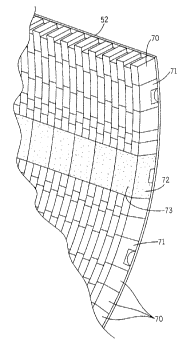
Referring now to Fig. 4, there is illustrated a portion of the refractory
material lining the interior of rotary kiln 18. The refractory material
includes a
plurality of bricks composed of a refractory material which are disposed
longitudinally and circumferentially adjacent one another. The bricks are
formed in
longitudinal rows extending parallel to the axis of kiln 18, and are either of
the
conventional type traditionally used in kilns, such as that designed by the
numeral
70, or are of the new design of the present invention, designated by numeral
71, and
referred to herein as refractory channel port (RCP) bricks. In one embodiment,
-10-
CA 02412727 2002-12-12
WO 01/96799 PCT/USO1/17973
there are six rows of conventional bricks 70 for each row of RCP bricks 71.
This
results in a total of twelve rows of the RCP bricks 71 disposed about the
interior or
inner surface of the shell 52 of kiln 18. However, as previously noted herein,
any
combination of rows of conventional bricks 70 and RCP bricks 71 may be
employed
depending upon the end use for kiln 18. It should be noted that the bricks 70
and 71
are disposed in a staggered arrangement which results in a pattern providing a
more
stable lining as kiln 18 rotates. Fig. 4 also illustrates a row of key blocks
72. Each
block 72 includes a top face 73 which is flush with the top faces of bricks 70
and 71.
Blocks 72 also include a bottom face (see Figs. 12-14) which abuts against the
inner
surface of shell 52. The blocks 72 are welded to shell 52, as will hereinafter
be
described, and thus prevent bricks 70 and 71, which are not fixed in any
manner to
shell 52, from rotating within shell 52 as kiln 18 rotates. Since bricks 70
and 71 are
not attached to shell 52, key blocks 72 thus maintain alignment of bricks 71
with the
ports of the air delivery system hereinafter to be described.
Fig. 5 illustrates a top view of an assembled row of RCP bricks 71. By
removal of adjacent rows of conventional bricks 70, the staggered arrangement
for
bricks 71 is clearly demonstrated. It should also be noted that the
horizontally
dashed lines in Fig. 5 illustrate a main air conveying channel 74 formed in
bricks
71 while the vertically extending dashed lines illustrate a plurality of air
vent
channels 75 disposed between each adjacent brick 71, both of which will
hereinafter be described in more detail.
Fig. 6 is a section view taken through the middle of the row of bricks 71
illustrated in Fig. 5. Fig. 6 illustrates in more detail that the main air
conveying
channel 74 is disposed along the inner surface of shell 52 to extend
longitudinally
and parallel to the axis of shell 52. Main air conveying channel 74
communicates
with the air inlet ports 50 as well as with the air vent channels 75. The air
vent
channels 75 communicate between the main air conveying channel 74 and extend
through bricks 71 into the interior chamber of shell 52, as will hereinafter
be
described in more detail.
-11-
CA 02412727 2002-12-12
WO 01/96799 PCT/USO1/17973
Fig. 7 illustrates an enlarged cross-sectional view of an assembled row of
RCP bricks 71. Fig. 7 illustrates in more detail that air vent channels 75 are
formed
between each adjacent brick 71 and each vent channel 75 has a double dogleg
configuration. Also, it should be noted that the bottom or lower portion 76 of
each
channel 75 is wider than the top or upper portion 77 of channels 75. Central
portion 78 of each channel 75 is angled with respect to portions 76 and 77,
and
interconnects portions 76 and 77. As illustrated, the longitudinal axis of
upper
portion 76 is offset from the longitudinal axis of lower portion 77 which
provides
the double dogleg configuration illustrated.
Figs. 8a and 8b are perspective views of one RCP brick 71 illustrating front
and rear views respectively. Each brick 71 includes a front face 79, a rear
face 80,
a top face 81, a bottom face 82, and opposite end faces 83 and 84. A main air
opening 85 is formed in the bottom face 82 of brick 71 and extends from the
front
face 79 to the rear face 80 thereof. Main air opening 85 is substantially LT-
shaped
in cross section, although other cross-sectional shapes may also be employed.
In
order to form air vent channels 75, each brick 71 includes a top air vent
passage 86
formed as a recess in the front face 79 of brick 71. Top air vent passage 86
extends
downwardly from top face 81 to a lower end 87 located between top face 81 and
bottom face 82. Preferably, lower end 87 is located slightly above air opening
85,
as shown best in Fig. 8a. Lower end 87 is comprised of a bevel surface which
is
about 15°-45°, preferably 30°, from vertical, as shown
best in Fig. 11. Also, as
shown best in Fig. 10, the edges of air vent passage 86 are rounded or
radiused to
minimize stress. Preferably, the air vent passage 86 is formed as a
rectangular
recess in front face 79, and as shown best in Fig. 11, it preferably is
recessed
approximately 0.19 inches from the plane defined by front face 79. It should
be
noted that the depth of passage 86 is dependent on kiln feed material being
processed.
Referring now to Fig. 8b, there is illustrated a bottom air vent passage 88
formed as a recess in the rear face 80 of each brick 71. Bottom air vent
passage 88
- 12-
CA 02412727 2002-12-12
WO 01/96799 PCT/USO1/17973
extends upwardly from bottom face 82 toward upper end 89 located between
bottom face 82 and top face 81. As illustrated best in Fig. 1 l, upper end 89
is
formed as a beveled surface of about 15°-45°, preferably
30°, from vertical. As
illustrated best in Fig. 8b, bottom air vent passage 88 is formed as a
rectangular-
shaped recess in rear face 80, and as illustrated in Fig. 10, its side edges
are
rounded or radiused to minimize stress. Fig. 11 illustrates that bottom air
vent
passage 88 is recessed from the plane defined by rear face 80 of brick 71
about 0.25
inches and is thus slightly deeper than top air vent passage 86. The depth of
passage 88, like that for passage 86, is dependent on the kiln feed material
being
processed. Thus, when assembled, lower portion 76 of air vent channel 75 will
be
slightly wider than upper portion 77 as illustrated in Fig. 7. Also, it is
important to
note that the lower end 87 of top air vent passage 86 extends below the upper
end
89 of bottom air vent passage 88, as seen best in Fig. 11. In other words,
lower end
87 meets or merges with front face 79 about 6 inches below top face 81 whereas
upper end 89 meets or merges with rear face 80 about 5.5 inches below top face
81.
As a result, when assembled, the angled central portion 78 of air vent channel
75 is
formed, as illustrated in Fig. 7.
Thus, when one brick 71 is positioned so that its front face 79 abuts against
the rear face 80 of an adjacent brick 71, the main air openings 85 of each
brick 71
are aligned to form the main air conveying channel 74. In addition, the top
vent
passage 86 of one brick is aligned with the bottom air vent passage 88 of an
adjacent brick to form the desired air vent channel 75 into the interior of
the kiln
18, as best illustrated in Fig. 7. Finally, it should be noted that main air
opening 85
is aligned vertically (see line 90 in Fig. 9) with top air vent passage 86 and
bottom
air vent passage 88 with each having approximately the same width. However,
main air opening 85, top air vent passage 86 and bottom air vent passage 88
are
also offset with respect to a vertical line running through the center of
brick 71.
This is necessary since the bricks 71 are assembled in a staggered arrangement
-13-
CA 02412727 2002-12-12
WO 01/96799 PCT/USO1/17973
shown best in Fig. 5. In other words, if brick 71 is 12 inches in width, line
90 is
located 7 inches from end face 84 and 5 inches from end face 83.
Referring now to Figs. 12-14, the key blocks 72 previously referred to in
connection with Fig. 4 are illustrated in more detail. I~ey blocks 72 are
attached to
kiln shell 52 to prevent the refractory bricks 71 from rotating within shell
52.
These key blocks 72 thus maintain alignment of the air inlet ports 50 with the
main
air conveying channel 74 formed in bricks 71. More specifically, each key
block
72 includes a front face 91, a rear face 92, a top face 93, a bottom face 94,
and
opposite side faces 95 and 96. As shown best in Fig. 12, bottom face 94 abuts
against the inner surface of shell 52, and as best illustrated in Fig. 4, top
face 93 is
flush with top faces 81 of bricks 71. Each key block 72 is composed of a
castable
type refractory material suitable for service duty similar to that of bricks
71. A
channel-shaped opening 97 is formed inwardly from bottom face 94 and extends
through block 72 from front face 91 to rear face 92, when the castable
refractory
material is formed around and anchored to a C-shaped steel channel 98 therein.
As
shown best in Fig. 12, the legs of steel channel 98 are flush with bottom face
94 of
block 72. However, as shown best in Fig. 13, front end 99 of steel channel 98
is
recessed inwardly from front face 91 whereas the rear end 100 of steel channel
98
projects outwardly from rear face 92 of block 72. A pair of spaced pins 101
and
102 are welded to the interior of steel channel 98, and as best shown in Fig.
13,
project outwardly from front end 99 so as to be flush with front face 91 of
block 72.
A recess 103 in front face 91 accommodates the projecting end of pins 101 and
102.
In order to assemble blocks 72 as shown in Fig. 14, a 2 inch long piece of
steel channel (not shown) is welded to the inner surface of shell 52. A first
block is
then positioned with pins 101 and 102 secured underneath this 2 inch long
piece of
steel channel. The first block is welded as at 104 to the inner surface of
shell 52.
Thereafter, a second block is positioned behind first block so that its front
face 91
abuts against the rear face 92 of the block 72 which has been welded to shell
52.
- 14-
CA 02412727 2002-12-12
WO 01/96799 PCT/USO1/17973
This second block 72 is then also welded to shell 52. It should be noted that
pins
101 and 102 on the second block are used to properly align the second block
with
respect to the first block since the projecting ends of pins 101 and 102 are
received
within the rear end 100 of the steel channel 98 of the first block 72. The
above
procedure is repeated until an entire row of key blocks 72 are assembled
within
shell 52, as shown best in Fig. 4.
-15-