Note: Descriptions are shown in the official language in which they were submitted.
CA 02412728 2002-11-26
FIELD OF THE INVENTION
The present: invention relates to the field of material
handling, and more par.°t.icular iy, to triggering apparatuses for use
with material handling appara~_use~~ for particulate solid material,
and to material handling apparatuses for use with particulate
solid material.
BACKGROUND OF THE INVENTION
It is not uncommon in ~~ modern factory for a large
r:umber of molding or extrusic:~n devices to be present. Typically,
1G such devices utilize plastic resin in parti<~ulate solid (powder or
pe'iiet) form as a feedstock. To ~;impl.ify inventory, as well as
material handling, particulate solid plastic resin is shipped in
lpulk to a central storage area in vhe factory. From the central
at.orage area, a plurality of conduits extend, each conduit
t=erminating at a respective loader dedicated to one of said
mo:~ding or extrusion devicws. Each loader includes a hopper
wapable of receiving a vol.um,.~ of said resin and in which a vacuum
a:ar: be formed, to draw said resin .from the central storage area,
through the conduit and into the hopper. When the hopper has been
f~.lled, the vacuum ceases to be drawn, and a discharge port in the
:ease of the hopper opens t:o discharge the collected resin material
into a receptacle disposed k~eneath the hopper. As the level of
the material in the receptacle drops, the discharge port can be
:losed, so as to permit further resin material to be drawn into
t.ne hopper, to repeat the process.
Closure of the c:~isch.arge port: can, of course, be
triggered manually, but it i~ advantageous tc automate the
process.
A variety of devices are known in the prior art: to
automatically trigger such closure of the discharge port.
Optical-based devices ar_e currently favoured, for reasons of
pc.zrchase economy ana reliability. However, it is possible for the
" lens" portion of sc.zch dev:i~:ves t:o become r_~oated with resin dust,
- 1 -
CA 02412728 2002-11-26
or otherwise soiled, whereupon operation becomes unpredictable.
As such, maintenance requirements for triggering apparatus of this
type can be substantial.
SiJMMP~RY OF THE INVENTION
Tt i.s an object: of the present invention to provide a
trigger apparatus for use ;aith a material port through which a
flow of particulate :.colic! material selectively passes, said
trigger apparatus ageing reiatiweiy economical and reliable and
riaving lesser maini:enanc:e requirements than devices of similar
economy and reliability in th~~ prior art.
This c:~bject, and others, is met by one aspect of the
present invention, a trigger apparatus for ~.zse with a material
port through which a flow of particulate solid material
selectively passes.
The trigger apparatus comprises a trigger body, a bias
means and a sensor means..
The trig=her bods,~ has a first position and a second
position and definE_~s a t:hrF~shold level of said particulate solid
material. The trigger body ~s adapted to be positioned, in use,
~0 beneath said material porte so as be impinged upon by said flow
when at its first posit-Lion and moved therefrom by said flow to its
second position. The trigger body i_s further adapted, upon
accumulation of said ~~ar.~:ic.ul.at.e solid material from said flow
beneath said material poet bey~~nd the threshold level, to be
restrained as against movement to said first position by said
particulate solid material until such time as the particulate
solid material recedes to said threshold level.
The bias means is for biasing the trigger body for
movement to its first pos.tion.
- 2 -
CA 02412728 2002-11-26
The sensor mean;~ is for producing a signal responsive to
movement of the trigger body to its f_z:rst position.
As other aspects o:E the invention, the trigger body
preferably comprisE::s a vane portion which, in use, is impinged
upon by said flow, wrnich imp_i.ngemer.t provides for said movement of
the trigger body from its first position to its second position.
As another aspect of the invention, the trigger
apparatus preferably further comp rises a float portion.
As a further <~speci= of: the invention, in non-flow
1C conditions when said particulate solid material has accumulated
f;:,om said flow benea:~th said material port: beyond the threshold
LF~vel, said particulate solid mar_erial preferably blocks movement
a: f= the float port ion, in t he course of said movement of the
ar.igger body from _t.s seccsnd position t:o its first position
1.5 through the agency o:fv the bi_,:rs means, thereby to provide for said
rr:igger body to be restraim-'d as against movement to said first
~:osition by said particulate solid material until such time as the
;.,Grticulate solid material recedes to said threshold level.
A material. handling apparatus including the trigger
2C apparatus and for us~~ with particulate solid material is another
aspect of the invent:i_on.
In addition to tr:e trigger apparatus, the material
rvandling apparatus compri:,es a loader.
The loader includE:s a hopper, a discharge cone, an
25 actuator means and a rec~aptar:le.
The hopper is for receeiving said particulate solid
material and has a disch<3rge port at the base thereof.
CA 02412728 2002-11-26
The discharge cone has an open position, apart from the
discharge port, whereat par,~iculat.e solid material within said
hopper can flow through said discharge port, and a closed
position, occluding said discharge port, whereat said flow is
arrested.
The actuator rr~earls is for selectively moving the
<ii_scharge cone between the open position and the closed position
thereof.
The receptacle is positioned beneath said hopper to
receive particulate solid material di:~charged through said
discharge port.
The trigger apparatus is used with the loader with the
discharge port of raid hopper defining the material port, the
q~rigger body being operatively mounted to the loader for movement
between its first pos~tior; and its second position, and the
actuator means being adapted to move the discharge cone to the
closed position thereof in ~:esponse to the signal from the sensor
means.
Other advantages, features and characteristics of the
2C present invention, ~s we:l1 as mf=tnods of operation and functions
of the related eiementc of t=he structure, and the combination of
~>arts and economies of manuf acture, will become more apparent upon
c.~:~nsideration of the following detailed description and the
appended claims with reference to the accompanying drawings, the
latter of which is briefly described hereinafter.
BRIEF DESCRIPTION OF THE DRAWINGS
Figure 1 is a p~:~.rspect..ive partial cutaway view of a
preferred embodime~at of the trigger apparatus of the invention in
~_zse with a loader t:.o form t:he material handl-ng apparatus of the
invention.
- 4 -
CA 02412728 2002-11-26
Figure 2 is a side elevat:ional view of a portion of the
structure of Figure 1, with h:.dden parts shown in phantom outline.
Figure 3 is a view similar to Figure 2, in initial flow
conditions, with the discharge core of the loader shown at its
open position and the trigger body pivc>t~ed toward its second
position.
Figure 4 is a view similar_ to Figure 3, in flow
~anditions, with the trigger body pivoted t.o its second position.
Figure 5 is a view similar to Figure 4, in non-flow
,conditions, wherein particulate solid material from said flow has
accumulated beneath the discharge port of the hopper.
Figure 6 is a T_~iew similar to Figure 5, wherein
<~,_~cumulated particulate solid material :frc>rn said flow has receded.
Figure 7 is a view similar to Figure 6, wherein
accumulated particulate soled material from said flow has receded
fi.irther.
Figure 8 is a view similar to Figure 7, wherein the
accumulated particulate solid material has receded to the
threshold level.
2C Figure 9 is a view similar to Figure 8, wherein the
trigger body has pivoted to its first position, and the
particulate solid material .nas receded below t=he threshold level.
Figure 10 i~ a view similar to Figure 9, with the
discharge come at p.ts ~losc-'d position.
Figure 11 is a f_r_ont, trop, right side perspective view
:~f the trigger body of F'ig~.~re 1.
_ c, _
CA 02412728 2002-11-26
DETAILED DESCRIPTION OF A PREFERRED EMBODIMENT
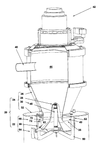
Referring general?y to Figures 1-10 of the drawings, a
material handling a~:~parat.us according to the invention is shown,
said apparatus being designated with general reference numeral 20
in Figure 2.
The material handling apparatus 20 includes a preferred
embodiment of the trigger apparatus of the invention in use with
a loader which are designated, respectively, with general
reference numerals ?2 anc~ 24.
For simplicity, trie loader 24 will firstly be described,
and will be understood to include a hopper, a discharge cone,
actuator means and a receptac:Le,, designated respectively with
general reference r~umerais 26, 28, 30 and 32.
The hopper 2E> is for receiving particulate solid
material and has a discharge port 36 at the base 40 thereof. The
:chopper 26 is of the type ~ ncludW g an evacuation fan 42 which
draws air from the interior 94 of the hopper ?6, so as to provide
for particulate solid ma'.eria.l to be conveyed pneumatically
through a conduit 46 e~aendinc~ to a central storage area (not
-hown.) . " Particulate s,ol ~_d m<~tc~rial" , for the purpose of the
present c~esc:ription anc~ ~_'laims, shall be taken to mean any
particulate solid mat.er_ial. capable of fluidic flow, such as
:granular material or powder mater__al, and especially plastic resin
chowder.
The discriarge cone 28 has an open position, apart from
the discharge port 36 <~nd .shown, inter a~'.ia, in Figure 4, whereat
particulate solid material 34 within said hopper 26 can flow
'through said discharge port 36, and a closed position, occluding
said discharge port:. 36 and shown in Figure 2, whereat said flow is
arrested.
CA 02412728 2002-11-26
The actuator me~ins 30 is for selectively moving the
discharge cone 28 between the open position and the closed
po,~ition thereof and, in the preferred embodiment illustrated
representatively in Figure l, comprises a pneumatic cylinder 48
which securely ext ends between the dischargf_ cone 28 and a bracket
'~0 spanning beneath the discharge port 36 and which is coupled by
a conduit 52 to a suitak:>le :supply of compressed air (not shown)
f:or extension.
The receptacle 32 is positioned beneath said hopper 26
f.0 r_c; receive particulate stolid material 34 discharged through said
discharge port 36.
Turning now to the trigger apparatus 22 of the preferred
embodiment, same wil.1 be understood to comprise a trigger body,
bias means and sense>r means, designated respectively with general
15 reference numerals 54, 56 and 58, and t:o be for use with a
material port: throu<:~h which a flow of particulate solid material
selectively passes, which material port, in the material handling
apparatus 20 illustrated, is deffined by the discharge port 36 of
the hopper 26.
20 As best indicated in Figure 11, the trigger body 54
defines a trigger axis A-A and comprises a vane portion 60 and a
float portion 62, each being substantial7_y planar and orientated
substantially para:11e1 to :>aid trigger a~;is A-A.
As ill.ust.rated in Figure 1, the trigger body 54 is
25 positioned beneath said cischarge port 36, and is pivotally
mounted to the loader ?4, ~>pecifically, t.o bracket 50 thereof, by
a pivot pin 63, fair movemt~nt: between a first position shown in
Figure 2 and a second position shown in figure 4.
As best illustrated in Figure 11, the trigger body 54
30 further comprises side wal:Ls F~4, 64, ~~ top wall 66 and wing
_ 7 _
CA 02412728 2002-11-26
portions 68,68, which wild. be fully described in following
paragraphs.
The bias means 56 is fcr biasing the trigger body 54 for
movement to its first pcsi.~.ion and in the preferred embodiment
illustrated is provided by forming trigger body 54 such that, when
at its first pcsitlcn, Its r_entre of gravity L3 is disposed beneath
the trigger axis A-A, as is indicated in Figure 2.
The sensor- means c;8 is for producing a signal responsive
t:o movement of the trigger body 54 to its first position, and in
the preferred embodimerut illustrated comprises a magnetic switch
~'0 and a magnet 72 mounted to and forming part of, respectively,
she loader 24 and the t.ri~~ger body 54 such that, at the first
-position of the trigger body 54, as shown in Figure 1, magnet 72
actuates the magnetic switch 70.
In opera'_ion, the hopper 26 wild_, as illustrated in
Figure 2, initially contain a volume: of particulate solid
material, and the discharge cone %8 will be disposed at its closed
posltlon.
When thf.~ rLc:eptaclE: 32 :is in need of additional
particulate solid mgrerlo:ii, this discharge cone 28 is moved,
through the agency of actuator means 30, to its open position, as
shown in Figure 3, -.o permit flow of said particulate solid
material 34. The direction pi= flow is indicated in Figure 3 by
arrow c:..
As W 11 be evicvient, upon comparison of Figure 2 and
Figure 3, at initial flow conditions, the trigger body 54, and
more specifically, the vane por'..ion 60 thereof, is positioned so
as to be impingecz upon by said flow, with the vane portion 60
orientated substantially ;:normal to the direction C of said flow at
the location of impirug~~ment.
_ g _
CA 02412728 2002-11-26
This impingement provides for_ movement of the trigger
body 54 from its first position to its second position, as
indicated by the direction o.v arrow D in Figure 2. Aforementioned
wing portions 68,63 work to impede flow of solid particulate
material 34 around the vane portion 60, thereby to increase drag
f~~~rces and resultant pivotal movement of t:he trigger body 54.
During such flow, ~:>articulate solid material accumulates
in the receptacle 32.
Flow continues into the receptacle 32 until hopper 26 is
~0 empty, whereupon the trigge~.r body 54, more specifically, the vane
portion 60 thereof, is immersed in said particulate solid material
as shown in Fig~.are 5.
In contrast, float port::.on 62, which is disposed apart
from the flow, as sr~own in Figure 4, remains above the accumulated
solid particulate material. So as to minimize the potential. for
particulate solid material accumulating c>n the float portion 62,
-he aforementioned side wails ~~4,.64 and r_op wall 66 are secured
atop the float portion 62, as be;~t seen ~n Figure 11, to impede
spillover during fl. ow ~-cnd..tion.s. In tried event that particulate
solid material is inadvertently deposited on the float portion 62
in flow conditions, the float portion 62, side walls 64,64 and top
wall 66 together form a ~:hute '74, to provide egress for such
deposited material,
In condi.~ions a:v showrv in Figure 5, movement of the
trigger body 54 to its fi.x,st po:>ition through agency the
the of
bias means 56 i.s arrested as a results of the accumulation of
particulate solid material around 60. As
the vane portion well,
movement of the trigger body ~4 is arrested as result the
a of
abutting contact of the float portion E' with the surface the
of
accumulated particulate solid material ~f4.
CA 02412728 2002-11-26
From the situation illustrated ire Figure 5, particulate
aoiid material may be drawn centrally from the receptacle 32, to
Feed a melt extruder, or the .Like (mot shown). As a result of this
entral withdrawal, slight "currents'" may be formed in the
particulate solid material 34, illustrated representatively by
arrow E in Figure 5, thereby producing crag forces on the vane
portion 60 which forces word: to urge the t=rigger body 54 towards
the first position, in ~:oncert with the moment forces created by
the bias means 56. However, the f7_oat. portion 62 is sized
sufficiently as not. to be drawn into the bulk. As a result,
trigger body 54 wi~.l pivot. only to follow the surface of the
accumulated particulate mat.c-~ria1 34, as indicated by the sequence
of Figures ',-8.
EventuallL~, as w=thdrawal continues, the particulate
solid material 34 will recE~de to a threshold level, as shown in
Figure 8, whereat any further material withdrawal will result in
t:he trigger body 54 becoming l.reed f.rorn the particulate solid
material 34, whereupon it u~i7_1 pivot, as indicated by arrow F in
figure 8, to its first position shown in Figure 9.
At this tome It stnould be noted that the threshold level
s not def fined merely by th<~ lowermost. extent of the float portion
at the moment before it becomE:s freed for rotation, since the
moment of the trigger body 59 at positions apart from the first
position thereof wil.1 be sufficient to dislodge a small amount of
particulate solid material, the quantum of which will depend upon
the physical characte:r_ist:.cs of the particulate solid material
being used.
Thus, for any given part.icui,~te solid material, the
Trigger body 54, anal mere s~>ecif.ica:lly, its geometric and
gravimetric particulars, W 1..1_ define the threshold level.
In any event., u~:~on movement of_ the trigger body 54 to
its first positio:~, as she>wn in Figure ~~, the magnet 72 actuates
- 1.0 -
CA 02412728 2002-11-26
the magnetic switch '70, theri~by generating a signal, in response
t:o which, the discharge cone 2~3 is moved by actuator means 30 to
the closed position, whereupon further particulate solid material
~:.:an be drawn into the hopper 26 for subseguent discharge, in the
conventional manner.
Other modifications <~nd alterations may be used in the
~~esign and manufact~_are ~.3f trie trigger apparatus according to the
present invention w~.thout departing from its spirit and scope.
For example, whereas the sensor means of the preferred
embodiment illustrated ~~cmpx~ises a magnet=is switch, other sensor
arrangements, for e~:ample, contact switches, could be used.
As well, whereas the vans portion and the float portion
of the preferred ~~mbc>dime:lt are substantially planar, other
configurations coul~:~ bE: utilized, and indeed, the float portion
c:~.>l.Ald be omitted ait:oget.her, in which even, immersion of the vane
portion in the part.iculat=e solid material would control movement.
to the first position.
Yet further, wherea:~ in the preferred embodiment
i~.lustrated, the vane poz-tion is initially immersed in the
L,articulate solid rr~atexial, this need not be the case.
Add.itionaily, whereas in the preferred embodiment
illustrated, the bias means is provided by a manner of weighting
t he trigger body, ether rnecrlanism:~, such as spring-biasing, could
be utilized with similar utility.
As well, whereas in the illustrations, the threshold
level of the particu_Late solid material is shown to be
substantially undu~_atory, ~s a result of the manner in which the
material is withdrawn ' rom th.e receptacle, and the angle of repose
of the particulate solid mat=erial, it should be understood that
- 11 -
CA 02412728 2002-11-26
t-he r_hreshold leve_i need not follow t:he same contours as
illustrated, and indeed, need not he undulatory at all.
Accordingly, the scope of the present invention should
be understood as limited only by the accompanying claims,
p~_,rposively construed.
- 12 -