Note: Descriptions are shown in the official language in which they were submitted.
CA 02412887 2002-12-20
WO 01/97748 PCT/1B01/01049
DUAL ENDED HAIR REMOVER
BACKGROUND OF THE INVENTION
1. Field of the Invention
The present invention relates to a dual ended hair remover having depilating
and
epilating functions for removing hair from a user, and more particularly, to a
dual ended hair
remover having a casing with a depilating head fixed at one end thereof, an
epilating head
fixed at the opposite end thereof, and a handle which covers one of the
depilating and epilating
heads at a time while providing power to drive the other one of the depilating
and epilating
heads.
2. Description of the Related Art
Shaving devices are known which have multiple heads mounted thereon. The heads
may either be permanently affixed to a casing having a motor or may be
interchangeable. Such
a device may even include a depilating head and an epilating head. A
depilating head cuts
hairs from the skin of a user, whereas an epilating head plucks (pulls) the
hair from the skin of
the user.
JP 4-348704, published December 3, 1992 to Iwasaki, discloses a main body in
which a
motor is contained, an epilating block in which epilating means is contained
and a trimmer.
Both the epilating block and the trimmer are permanently affixed to one end of
the main body,
and they both operate simultaneously. The epilating block is at one side and
the trimmer is at
the other side of the same end, with the depilating block and the trimmer
being in close
proximity with each other. By being in close proximity with each other, there
is a risk of
injuring one's self through unintentional contact with the one of the
depilating block and
trimmer which is not intended to be used at a given time. In addition, as both
the depilating
block and trimmer operate simultaneously, although one is being used at a
given time,
unnecessary power is being used to drive the epilating/depilating appliance.
SUBSTITUTE SHEET (RULE 26)
CA 02412887 2002-12-20
WO 01/97748 PCT/1B01/01049
U.S. Patent No. 3,672,049 issued June 27, 1972 to Demci et al. discloses
different
operating heads as separate units for individual operation. The operating
heads are both
trimmers, which are interchangeable with each other at the same end of the
casing 11. The
two different types of trimmers are mounted one at a time to the casing 11. As
a result, effort
is required to interchange the two heads to perform the two different types of
trimming and
extra wearing of the components result from the repeated changing of the
heads. Both heads
are trimmers, and neither one performs the function of epilation. Also, as
only one head is
mounted at a time, the unmounted head may easily be lost by the user when not
in use.
U.S. Patent No. 5,611,804 issued March 18, 1997 to Heintke et al. discloses a
casing 2
which is adapted to receive a first attachment incorporating an epilating
cylinder, or
alternatively, a second attachment incorporating a long-hair trimmer. The
first and second
attachments are interchangeable with each other at a same end of the casing 2.
Although
Heintke et al. performs both the epilating and depilating functions, the
appliance disclosed
therein suffers from a number of the same drawbacks as are present in Demci et
al. Namely,
additional effort is required to replace the epilating head with the
depilating head, and vice
versa, when alternating between the epilating and depilating functions, and
extra wearing of
the components result from the repeated changing of the heads. Also, the
unattached head may
easily be lost by the user when not in use.
Other devices are known which have a shaving head and a long-hair trimmer at a
same
end of a casing, wherein either the shaver is in operation or both the shaver
and the long-hair
trimmer are in operation. In these devices, it is often easy to accidentally
activate the long-hair
trimmer, causing possible injury to the user when such operation is
unaccounted for. Further,
through the simultaneous operation of both the shaver and the long-hair
trimmer, unnecessary
power is required to drive both heads. Still further, such devices do not
enable the epilation
function to be performed.
SUMMARY OF THE INVENTION
Accordingly, it is an object of the present invention to provide a dual ended
hair
remover having both a depilating function and an epilating function.
2
SUBSTITUTE SHEET (RULE 26)
CA 02412887 2002-12-20
WO 01/97748 PCT/1B01/01049
It is another object of the present invention to provide a dual ended hair
remover having
a casing and a depilating head and an epilating head fixed at respective
opposite ends of the
casing.
It is a further object of the present invention to provide a dual ended hair
remover
having a casing, depilating and epilating heads fixed at respective opposite
ends thereof, and a
handle which alternately attaches to the opposite ends of the casing so as to
cover one of the
depilating and epilating heads while providing power to the other one of the
depilating and
epilating heads.
It is a further object of the present invention to provide a dual ended hair
remover
having a casing, depilating and epilating heads fixed at respective ends
thereof, so as to
lengthen the durability of the heads since there is no need to repeatedly
detach and reattach the
same.
It is still a further object of the present invention to provide a dual ended
hair remover
having a casing, depilating and epilating heads simultaneously fixed to the
casing, and a handle
which covers one of the depilating and epilating heads while providing power
to the other one
of the depilating and epilating heads.
It is still yet further another object of the present invention to provide a
dual ended hair
remover having a casing, depilating and epilating heads simultaneously fixed
to the casing, and
a handle which covers one of the depilating and epilating heads while
providing power to the
other one of the depilating and epilating heads, wherein the casing has a
motor for driving the
depilating and epilating heads, and a coupling unit to disengage the one of
the depilating and
epilating heads covered by the handle while engaging the motor and the one of
the depilating
and epilating heads which is not covered by the handle.
Additional objects and advantages of the invention will be set forth in part
in the
description which follows and, in part, will be obvious from the description,
or may be learned
by practice of the invention.
The above objects of the present invention are achieved by providing a dual
ended hair
remover to remove hairs from skin of a user, comprising a casing having first
and second ends
opposite each other, an epilating head mounted on the first end, to pluck the
hairs from the
3
SUBSTITUTE SHEET (RULE 26)
CA 02412887 2007-10-04
skin of the user, and a depilating head mounted on the second end, to cut the
hairs from the
skin of the user.
The above and other objects are further achieved by providing a dual ended
hair
remover to remove hairs from skin of a user, comprising a casing having first
and second ends
opposite each other, an epilating head mounted on the casing, to pluck the
hairs from the skin
of the user, a depilating head mounted on the casing, to cut the hairs from
the skin of the user,
and a handle to alternately cover the epilating head and enable driving of the
depilating head,
and cover the depilating head and enable driving of the epilating head.
The above and other objects are still further achieved by providing a dual
ended hair remover
to remove hairs from skin of a user, comprising a casing having first and
second ends opposite
each other, an epilating head mounted on the casing, to pluck the hairs from
the skin of the
user, a depilating head mounted on the casing, to cut the hairs from the skin
of the user, and a
handle to alternately cover the epilating head and enable driving of the
depilating head without
enabling driving of the epilating head, and cover the depilating head and
enable driving of the
epilating head without enabling driving of the depilating head.
In accordance with an aspect of the present invention, there is provided a
dual ended
hair remover to remove hairs from skin of a user, comprising a casing having
first and second
ends opposite each other; an epilating head mounted on the first end, to pluck
the hairs from the
skin of the user; and a depilating head mounted on the second end, to cut the
hairs from the
skin of the user.
According to another aspect of the present invention, there is provided a dual
ended
hair remover to remove hairs from skin of a user, comprising a casing having
first and second
ends opposite each other; an epilating head mounted on the casing, to pluck
the hairs from the
skin of the user; a depilating head mounted on the casing, to cut the hairs
from the skin of the
user; and a handle to alternately cover the epilating head and enable driving
of the depilating
head, and cover the depilating head and enable driving of the epilating head.
4
CA 02412887 2007-10-04
BRIEF DESCRIPTION OF THE DRAWINGS
These and other objects and advantages of the invention will become apparent
and more
readily appreciated from the following description of the preferred
embodiments, taken in
conjunction with the accompanying drawings of which:
FIGS. 1A and 1B are perspective views of a dual ended hair remover having a
handle
being attached to one end of a casing so as to cover an epilating unit and
attached to the other
end of the casing so as to cover a depilating unit, respectively;
FIGS. 2A and 2B show a plan view and a perspective view of an internal
mechanical
configuration of the casing according to the first embodiment;
FIGS. 3A and 3B show electrical circuitry of the dual ended hair remover when
the
handle is attached to one end and the other end of the casing, respectively,
according to the first
embodiment of the present invention;
4a
CA 02412887 2002-12-20
WO 01/97748 PCT/1B01/01049
FIGS. 4A through 4D show various views of contacts exposed externally from the
casing and terminals of the handle which contact the contacts of the casing
according to the
first embodiment of the present invention;
FIGS. 5A through 5D are various views of the internal electrical system
according to
the first embodiment of the present invention using a two-contact AC system;
FIGS. 6A and 6B show a plan view and a perspective view of an internal
mechanical
configuration of the casing, respectively, according to a second embodiment of
the present
invention;
FIGS. 7A and 7B show a plan view and a perspective view of an internal
mechanical
configuration of the casing, respectively, according to a third embodiment of
the present
invention;
FIGS. 8A and 8B show a plan view and a perspective view of an internal
mechanical
configuration of the casing, respectively, according to a fourth embodiment of
the present
invention;
FIGS. 9A and 9B show a coupling unit having a coupler at first and second
positions,
to selectively drive an epilating head and a depilating head, respectively,
according to the
fourth embodiment of the present invention;
FIG. 10 shows a plan view of rotary gears and the coupler according to the
fourth
embodiment of the present invention;
FIGS. 11A and 11B show a cross-sectional view of the coupler at the first and
second
positions, respectively, according to the fourth embodiment of the present
invention;
FIG. 12 is an exploded view of the coupler according to the fourth embodiment
of the
present invention;
FIG. 13 shows a coupling mechanism to move the coupler between the first and
second
positions according to the fourth embodiment of the present invention;
FIG. 14 shows the coupling mechanism along with the coupler and attached to
the
handle according to the fourth embodiment of the present invention;
FIG. 15 is an in-depth view of the coupler and the coupling mechanism
according to the
fourth embodiment of the present invention;
SUBSTITUTE SHEET (RULE 26)
CA 02412887 2002-12-20
WO 01/97748 PCT/1B01/01049
FIG. 16 shows a coupling mechanism for driving the coupler between the first
and
second positions in a second aspect according to the fourth embodiment of the
present
invention;
FIGS. 17A and 17B show the internal electrical circuiting of a casing based
upon
whether a handle is attached to a first end or a second end of the casing,
respectively,
according to a fifth embodiment of the present invention;
FIGS. 18A through 18C are various views of contacts externally exposed from
the
casing and terminals of the handle according to the fifth embodiment of the
present invention;
FIGS. 19A through 19C are various views of the internal mechanical
configuration and
internal electrical circuitry of the casing according to the fifth embodiment
of the present
invention;
FIGS. 20A and 20B show the internal circuitry of a casing using a four-contact
AC
system according to a sixth embodiment of the present invention;
FIGS. 21A through 21C show various views of the contacts of the casing and
terminals
of the handle according to the sixth embodiment of the present invention;
FIGS. 22A and 22B show a plan view and a perspective view of the internal
mechanical
configuration of a casing according to a seventh embod'unent of the present
invention;
FIGS. 23A and 23B show the internal circuitry based upon whether a handle is
attached
to one end or the other end of the casing, respectively, according to the
seventh embodiment of
the present invention; and
FIG. 24 is a perspective view of the internal mechanical configuration and
internal
electrical circuitry of the casing according to the seventh embodiment of the
present invention.
DESCRIPTION OF THE PREFERRED EMBODIMENTS
Reference will now made in detail to the present preferred embodiments of the
present
invention, examples of which are illustrated in the accompanying drawings,
wherein like
reference numerals refer to the like elements throughout.
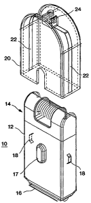
FIGS. 1A and 1B are perspective views of a dual ended hair remover in
accordance
with the first embodiment of the present invention. The dual ended hair
remover 10 has a
6
SUBSTITUTE SHEET (RULE 26)
CA 02412887 2002-12-20
WO 01/97748 PCT/1B01/01049
casing 12, an epilating head attached to one (a first) end of the casing and a
depilating head
(shaving unit) attached to the other (second) end of the casing 12. A pair of
contacts 18 are
exposed at respective opposite sides of the casing 12, in between the
epilating head 14 and the
depilating head 16. An on/off switch 17 extends from a middle of one of the
surfaces of the
casing 12 to control power to the epilating head 14 and the depilating head
16.
A handle 20 fits over either of the ends of the casing 12, selectively
covering the
epilating head 14 and the depilating head 16. A pair of terminals 22 are thin
strips of metal
extending in opposite directions from a power receptacle 24. The terminals 22
run along
opposite sides of inner walls of the handle 20.
FIG. 1A shows the handle 20 about to be placed over (attached to) the first
end of the
casing 12 so as to cover the epilating head 14, and FIG. 1B shows the handle
20 about to be
placed over (attached to) the other end of the casing 20 so as to cover the
depilating head 16.
Regardless of whether the handle is placed over the first end or the second
end of the
casing 12, the terminals 22 respectively come into contact with the contacts
18 to provide
electrical power to the contacts 18.
FIGS. 2A and 2B respectively show a plan view and a perspective view of the
interior
mechanical configuration region of the casing 12. A motor 26 is positioned
near a center of
the interior of the casing 12. First and second axles 30, 32 extend from
opposite sides of the
motor 26, the first axle 30 having an axis pointing toward the epilating head
14 and the second
axle 32 having an axis of rotation directed toward the depilating head 16.
When the handle 20
is placed over the epilating head 14 or the depilating head 16, the terminals
22 respectively
come into contact with the contacts 18, thereby providing power to the
contacts 18. The
contacts 18 provide power to the motor 26 (see description of the electrical
circuitry below),
thereby causing the first and second axles 30, 32 to rotate.
A rotary gear 34 is affixed to the end of the axle 30 and is concentric
thereto. A rotary
gear 36 is permanently engaged with the rotary gear 34, has an axis of
rotation parallel to that
of the rotary gear 34, and has teeth 38 extending from the surface of the
rotary gear 36 facing
away from the motor 26. A rotary gear 40 is positioned at a right angle to the
rotary gears 34
and 36, and permanently engages the teeth 38 of the rotary gear 36. A rotary
gear 42 is
7
SUBSTITUTE SHEET (RULE 26)
CA 02412887 2002-12-20
WO 01/97748 PCT/1B01/01049
affixed to an end of an axle 44 of the epilating head 14. Grippers 46 are
formed at the
periphery of an epilating cylinder 48 of the epilating head 14.
When the first axle 30 is driven by the motor 26, the rotary gear 34 is
rotated, thereby
rotating the rotary gear 36 and the teeth 38. The rotation of the teeth 38
causes the rotary gear
40 to rotate at a 90 angle relative to the rotary gear 36, thereby causing
the rotary gear 42 to
rotate. The rotation of the rotary gear 42 causes the axle 44 of the epilating
cylinder 48 to
rotate, thereby causing the grippers 46 to open and close, so as to pluck
hairs from the skin of
a user.
The motor 26 simultaneously drives the second axle 32, thereby causing a
shaving
element 50 to reciprocate back and forth relative to a fixed element 52. The
reciprocation of
the shaving element 50 relative to the fixed element 52 causes hair extending
from the surface
of the skin of the user between the shaving element 50 and the fixed element
52 to be cut.
FIGS. 3A and 3B show a first situation wherein the handle 20 covers the
epilating head
14, and a second situation wherein the handle 20 covers the depilating head
16, respectively.
The contacts 18 are connected to two opposite points of a regulator (a
wheatstone bridge) 54
and positive and negative poles 56, 58 of the motor 26 are connected to other
opposite points
of the regulator 54. A transformer 60 which is part of an external adapter
(not shown)
converts a 230V-110VAC from a wall socket 62 to 3V-18VAC which is transmitted
through
the power receptacle 24 to the terminals 22. When the handle 20 is placed over
the first end to
cover the epilating head 14 or the second end to cover the depilating head 16,
power is
supplied through the terminals 22 to the contacts 18, and subsequently to the
motor 26 through
the regulator 54 and the positive and negative poles 56, 58 of the motor 26.
As a result of this two-contact AC system, the electrical system forms an
adapter which
converts AC current to DC current inside the casing 12, so that there is no
importance placed
on the polarity of the contacts 18.
FIGS. 4A and 4B show a perspective view and a plan view of the dual ended hair
remover 10 having the two-contact AC system, respectively, shown in FIGS. 1A
through 3B.
FIG. 4C shows the electrical contacts 22 respectively in contact with the
contacts 18 when the
handle 20 (the external portion of the handle 20 not being shown herein) is
placed over the first
8
SUBSTITUTE SHEET (RULE 26)
CA 02412887 2002-12-20
WO 01/97748 PCT/1B01/01049
end of the casing 12 to cover the epilating head 14. FIG. 4D shows the
terminals 22 in contact
with the contacts 18, respectively, when the handle 20 (the external portion
of the handle 20
not being shown herein) is attached over the second end of the casing 12 to
cover the depilating
head 16.
FIGS. 5A through 5D show various views of the internal electrical circuitry
for the two
contact AC power system shown in FIGS. 3A through 4D. FIG. 5A shows a front
perspective
view of the electrical circuitry, FIG. 5B shows a back perspective view of the
electrical
circuitry, FIG. 5C shows the terminals 22 of the handle 20 (not shown in this
drawing)
contacting the respective contacts 18 when the handle 20 is mounted at one end
of the casing
12 to cover the epilating head 14, and FIG. 5D shows the terminals 22 in
contact with the
respective contacts 18 when the handle 20 (not shown in this drawing) is
mounted on the other
end of the casing 12 to cover the depilating head 16.
A printed circuit board (PCB) 21 has two diodes 23 and a switch 25 mounted
thereon.
The PCB 21 receives AC current from the contacts 18 which are supplied from
the terminals
22 (see FIGS. 5C and 5D).
FIG. 5B shows wires 27 that conduct the AC current from the contacts 18 from
both
sides to the rectifier 54 shown in FIGS. 3A and 3B, and then the DC direct
current is supplied
to the positive and negative leads (motor poles) 56, 58 of the motor 26.
A variety of other mechanical configurations and electrical circuitries may be
adapted
for use in the present invention, some of which are explained below.
FIGS. 6A and 6B show a plan view and a perspective view of the internal
mechanical
configuration of the casing 12 according to a second embodiment of the present
invention. The
mechanical elements and operation of the mechanical elements are substantially
the same as the
internal mechanical elements shown in FIGS. 2A and 2B with the following
exceptions.
Instead of the second axle 32 extending from the opposite side of the motor 26
to that of
the first axle 30 to reciprocatingly drive the shaving element 50, a second
axle 66 is attached to
the rotary gear 36 so as to extend parallel to the first axle 30 alongside the
motor 26 and past
the motor 26. The end of the second axle 66 opposite the rotary gear 36 is
attached to the
shaving element 50. When the motor 26 is driven, the first axle 30 rotates,
thereby rotating
9
SUBSTITUTE SHEET (RULE 26)
CA 02412887 2002-12-20
WO 01/97748 PCT/1B01/01049
the rotary gear 36. As a result of rotation of the rotary gear 34, the rotary
gear 36 rotates,
thereby rotating the second axle 66, to cause the reciprocating movement of
the shaving
element 50 relative to the fixed element 16. As a result, hair positioned
between the shaving
element 50 and the fixed element 52 is cut, as in the first embodiment. The
epilating cylinder
48 is driven simultaneously with the shaving element 50, with either the
epilating head 14 or
the depilating head 16 being covered by the handle 20.
FIGS. 7A and 7B show a plan view and a perspective view of the internal
mechanical
portion of the casing 12 for driving the epilating head 14 and the depilating
head 16 according
to a third embodiment of the present invention. In this third embodiment,
instead of the motor
extending in a lengthwise direction of the casing 12 in a direction from the
epilating head 14 to
the depilating head 16, the motor is rotated 90 from that of the first and
second embodiments
shown in FIGS. lA through 5B. In this third embodiment, the motor 26 extends
in a direction
from one side of the casing 12 to the other side, and not in a direction from
one end to the
other. A bracket 78 is fixed within the casing 12. The motor 26 is mounted in
the bracket 78
and is movable between a position A and a position B. The mounting of the
handle 20 on the
epilating head 14 or the depilating head 16 or a switch in the interior of the
handle 12 based
upon the mounting of the handle 12 on the epilating head 14 or the depilating
head 16 may be
used to move the motor between the positions A and B. The first axle 30
extends from one
side of the motor 26 and is rotated in conjunction with the driving of the
motor 26. The rotary
gear 34 is coaxial with and placed at the end of the first axle 30.
A rotary gear 38 has an axis of rotation parallel to the axis of rotation of
the rotary gear
34 and is positioned at a right angle relative to a rotary gear 70. A rotary
gear 70 has teeth 72
extending from a surface thereof to permanently engage with the rotary gear
68. The rotary
gear 70 is connected to the shaving element 50. A rotary gear 74 has an axis
of rotation
parallel to the axis of rotation of rotary gear 34, and is permanently engaged
with a rotary gear
76. The rotary gear 76 is permanently engaged with the rotary gear 40.
In the position A (when the handle 20 is mounted over the epilating head 14),
the rotary
gear 34 attached to the first axle 30 engages with the rotary gear 68, and is
disengaged from
the rotary gear 74. The rotation of the rotary gear 34 causes the rotary gears
68 to rotate,
SUBSTITUTE SHEET (RULE 26)
CA 02412887 2002-12-20
WO 01/97748 PCT/1B01/01049
thereby causing the rotary gear 70 to rotate through the interaction of the
teeth 72 with the
rotary gear 68. The rotation of the rotary gear 70 causes the shaving element
50 to move in a
reciprocating motion relative to the fixed element 52 of the depilation head
16.
When the motor 26 is in the position B (when the handle 20 is mounted over the
depilating head 16), the rotary gear 36 engages the rotary gear 74, and is
disengaged from the
rotary gear 68. The rotation of the rotary gear 34 causes the rotation of the
rotary gears 74,
76, 40, and 42, thereby causing rotation of the epilating cylinder 48. As a
result, the grippers
46 open and close to pull the hair, positioned between the grippers, from the
skin of the user.
The two contact system shown in FIG. 1A, 1B and 3A through 4B may be used to
power the motor 26.
In the third embodiment, because the motor 26 is movable between the positions
A and
B, it is possible to selectively drive the epilating head 14 and the
depilating head 16, only when
necessary. Therefore, if the epilating head 14 is covered by the handle 20,
only the depilating
head 16 need be driven. If the depilating head 16 is covered by the handle 20,
only the
epilating head 14 need be driven. Such a configuration saves power by not
simultaneously
driving both the epilating head 14 and the depilating head 16 while only one
head is being used
while the other one is covered.
FIGS. 8A and 8B show a plan view and a perspective view of the internal
mechanical
configuration and operation of the casing 12, respectively, according to a
fourth embodiment
of the present invention. Many of the mechanical parts are very similar to
those shown in
FIGS. 6A and 6B, except there are distinctions to enable selective driving of
the epilation head
14 and the depilation head 16 as in the third embodiment shown in FIGS. 7A and
7B. Like the
second embodiment shown in FIGS. 6A and 6B, the rotary gear 34 is currently
engaged with
the rotary gear 36. However, instead of the rotary gear 36 having teeth
extending from a
surface thereof, another rotary gear 80 is adjacent to the rotary gear 36, but
may or may not
rotate based upon the rotation of the rotary gear 36. The rotary gear 80 has
teeth extending
from a surface thereof in a direction toward the epilating head 14. Further,
the rotary gear 80
has a hole in the middle and protrusions 84 at a periphery of the hole and
extending from the
same surface as the teeth at 90 intervals. The second axle 66, unlike in the
second
11
SUBSTITUTE SHEET (RULE 26)
CA 02412887 2002-12-20
WO 01/97748 PCT/1B01/01049
embodiment shown in FIGS. 6A and 6B, extends beyond the rotary gear 36 and
through the
hole of the rotary gear 80. A spline 90 is fixedly formed at the end of the
axle 66 and has slots
92 formed at 90 intervals. A coupler 86 having protrusions 88 is selectively
moved linearly
to either engage the protrusions 84 or the slots 92 of the spline 90.
FIGS. 9A and 9B show a more detailed perspective view of the coupler 86
engaging the
protrusions 84 of the rotary gear 80 and the slots 92 of the spline 90,
respectively. FIG. 10
shows a plan view of the rotary gear 34 engaged with the rotary gear 36, and
the rotary gear
80 and the coupler 86 positioned above the rotary gear 36. FIGS. 11A and 11B
are cross-
sectional views of the coupling unit shown in FIGS. 9A and 9B, respectively.
FIG. 12 shows
an exploded view of the coupling unit shown in FIGS. 9A through 11B.
In FIGS. 9A and 1 1A, the coupler has been moved into a first position so that
recesses
94 formed therein to correspond with the protrusions 84 of the rotary gear 80
are engaged by
the protrusions 84. A description of the how the coupling moves between the
first and second
positions will be described later in the specification.
As shown in FIG. 12, the rotary gear 36 has a thickened region 96 extending
therefrom
and through the hole of the rotary gear 80. The thickened region 96 is coaxial
with the second
axle 66, and has slots 98 formed at 90 relative to each other and extending
along the
lengthwise direction of the second axle 66. The protrusions 88 of the coupler
86 are slidable
within the slots 98 of the thickened region 96, and as the rotary gear 36 and
the thickened
region 96 rotate, the coupler 86 is rotated through the interaction of the
protrusions 88 and the
slots 98.
A description of the mechanical operation according to the fourth embodiment
when the
coupler 86 is in the first position will now be described. As the motor 26 is
driven, the axle
30 rotates the rotary gear 34 so that the rotary gear 36 is rotated. The
rotation of the rotary
gear 36 causes the thickened region 96 to rotate so that the coupler 86
rotates through the
interaction between the slots 98 and the protrusions 88. The interaction
between the
engagement of the protrusions 84 of the rotary gear 80 and the recesses 94 of
the coupler 86
cause the rotary gear 80 to rotate. Because the teeth 82 of the rotary gear 80
are permanently
engaged with the rotary gear 40, the rotary gear 40 is rotated, thereby
rotating the rotary gear
12
SUBSTITUTE SHEET (RULE 26)
CA 02412887 2002-12-20
WO 01/97748 PCT/1B01/01049
42. As a result, the axle 44 is rotated, to thereby rotate the epilating
cylinder 48, which in
turn causes the grippers 46 to rotate and open and close. Based upon the
rotation and opening
and closing of the grippers 46, the hairs from the skin of the user are
plucked, to accomplish
the epilation function.
FIGS. 9B and 11B show when the coupler 86 is in the second position. At this
time,
the recesses 94 disengage from the protrusions 84 of the rotary gear 80, and
the protrusions 88
engage with the slots 92 of the spline 90. When the coupler 86 is in this
second position, the
protrusions 88, which extend through the height of the coupler 86 are within
both the
corresponding slots 98 and the corresponding slots 92.
When the motor 26 is driven, the first axle 30 rotates the rotary gear 34,
thereby
rotating the rotary gear 36. The thickened region 96 rotates in conjunction
with the rotary gear
36, thereby causing the rotation of the coupler 86 through the interaction of
the engagement of
the protrusions 88 within the corresponding slots 98. Simultaneously, the
protrusions 88 are at
least partially engaged in the corresponding slots 92 of the spline 90,
thereby rotating the
second axle 66. The rotation of the second axle 66 causes the shaving element
50 to move in
the reciprocating motion relative to the fixed element 52, thereby cutting the
hairs from the
skin of the user which are positioned between the sharing element 50 and the
fixed element 52.
FIGS. 13 through 15 show a coupling mechanism for moving the coupler 86
between
the first and second positions. FIG. 13 shows a fork 100 which is connected at
one end to the
coupler 86 so that a portion of the fork 100 goes around part of the periphery
of the coupler
86. The other end of the fork 100 is fixed to a lever mechanism 102 which
extends
perpendicularly from the bottom surface (see FIG. 12) of the fork 100. The
lever mechanism
102 includes an H-shaped bracket having a protrusion 107 fixed to an interior
portion of the
casing 12 so that the H-shaped bracket 109 is rotatable about an axis of the
cylindrical
protrusion 107. A cylindrical piece 103 is fixed in between one of the gaps of
the H-shaped
bracket 109 at one end and to the fork 100 at the other end thereof. A T-
shaped arm 105 has
one end fixed to the other gap in the H-shaped bracket 109. FIG. 14 shows the
coupler 86, the
fork 100 and the lever mechanism 102 (which are in the interior part of the
casing 12) which
are pushed in one direction by the handle 20 when the handle 20 is mounted on
the casing 12.
13
SUBSTITUTE SHEET (RULE 26)
CA 02412887 2002-12-20
WO 01/97748 PCT/1B01/01049
When the handle 20 is inserted over one end of the casing 12 to cover the
epilating head 14,
the T-shaped arm 105 is moved downward (in FIGS. 13 through 15), the H-shaped
bracket 109
is rotated clockwise about the cylindrical protrusion 107 and the cylindrical
piece 103 is
pushed upward, thereby pushing the fork and coupler upward to the first
position to engine the
spline 90. When the handle 20 is removed from the casing 12 and inserted over
the other end
of the casing 12 to cover the depilation 16, the T-shaped arm 105 is moved
upward, thereby
causing the H-shaped bracket 109 to rotate counterclockwise about the
cylindrical protrusion
107. As a result, the cylindrical piece 103 is pulled downward, thereby moving
the fork 100
and the coupler 86 downward to the first position. Then, the protrusions 84 of
the rotary gear
80 engage the recesses 94 of the coupler 86. A more detailed view of the
interaction between
the lever mechanism 102 and the fork 100 is shown in FIG. 15. The handle 20
contacts the
lever mechanism 102 through a track in the casing 12. When the handle 20 is
inserted over
one end of the casing 12 to cover the epilating head 14, the lever mechanism
102 pushes
against the fork 100 to move the coupler 86 to the second position. When the
handle 20 is
removed from the casing 12 and inserted over the other end of the casing 12 to
cover the
depilation head 16, the lever mechanism 102 pushes on the opposite side of the
fork 100 to
move the coupler 86. A more detailed view of the interaction between the lever
mechanism
102 and the fork 100 is shown in FIG. 15.
Based upon the positioning of the handle 20, the lever mechanism 102 pushes or
pulls
the fork 100 to selectively move the coupler 86 to the first and second
positions, thereby
selectively driving the one of the epilating head 14 and the depilating head
16 which is
positioned at the opposite end of the casing 12 from which the handle 20 is
mounted.
Therefore, when the handle 20 covers the epilating head 14, the depilating
head 16 is driven by
the coupler 86 being positioned at the second position, whereas when the
handle 20 covers the
depilating head 16, the epilating head 14 is driven by the movement by the
coupler 86 to the
first position.
Another possible coupling mechanism for moving the coupler 86 between the
first and
second positions to alternately engage the epilating head 14 and the
depilating head 16 is
shown in FIG. 16 according to another aspect of the fourth embodiment of the
present
14
SUBSTITUTE SHEET (RULE 26)
CA 02412887 2002-12-20
WO 01/97748 PCT/1B01/01049
invention. A spring 104 biases the lever mechanism 102 so that the fork 100 is
in either the
first or second position, and as shown in the drawing, biases the lever
mechanism 102 so that
the fork 100 is in the second position so that the protrusions 88 engage the
slots 92 of the
spline 90. When the handle 20 is mounted on the depilating head 16, the handle
20 moves the
lever mechanism 102 to push down on the fork 100, thereby movingthe coupler 86
to the first
position against the bias of the spring 104. As a result, the coupler 86
disengages from the
spline 90 and the recesses 94 of the coupler 86 are engaged by the protrusions
84 of the rotary
gear 80. When the handle 20 is removed from the depilating head 16, the
coupler 86 is moved
back to the second position through the bias of the spring 104.
Based upon the two aspects described above regarding the movement of the
coupler 86
between the first and second positions, it is possible to alternately engage
the epilating head 14
and the depilating head 16, so that only one head is operating at a given
time. As are result,
power is conserved, and wear and tear on the epilating and depilating heads
14, 16 are
minimized.
Of course, one of ordinary skill in the art would recognize that there are any
number of
different ways to move the coupler 86 between the first and second positions
to selectively
engage the splines 90 and the protrusions 84 of the rotary gear 80.
FIGS. 17A through 19C show another electrical system for supplying power to
the
motor 26 using a three-contact AC system according to a fifth embodiment of
the present
invention. In the three-contact AC system, the transfer of current is
performed by an adapter
within a casing 112, wherein there are three contacts instead of two. FIGS.
17A and 17B
show the internal schematic drawings of the power electrical system of the
dual ended hair
remover when the handle 20 is attached to one end of the casing 112 which
covers the epilating
head 14 and when the handle is connected to the other end of the casing 112 to
cover the
depilating head 16. As shown in FIGS. 18A through 18C, the casing 112 differs
from the
casing 12 in that there are three contacts 114, 116 and 118 which are exposed
externally from
the casing 112. The handle 20, instead of having terminals 22 extending along
the inner
peripheries of opposite sides of the handle 20, has terminals 122, 124
extending along an inner
surface of the back of the handle 20.
SUBSTITUTE SHEET (RULE 26)
CA 02412887 2002-12-20
WO 01/97748 PCT/1B01/01049
The central contact 116 has a positive polarity, while the outside contacts
114, 118 have
a negative polarity and are connected together. The central contact 116 is
connected to one
end of the rectifier 54, whereas the outside contacts 114 and 118 are
connected to the other end
of the rectifier 54.
As shown in FIGS. 17A and 18B, when the handle 20 is attached at one end of
the
casing 112 to cover the epilating head 14, the terminal 124 contacts the
center contact 116 and
the terminal 122 contacts the outer contact 114. As shown in FIGS. 17B, 18C
and 19B, when
the handle 20 is attached to the other end of the casing 112 so as to cover
the depilating head
16, the terminal 124 contacts the center contact 116 and the terminal 122
contacts the outer
lead 118.
FIG. 19C shows a closeup of FIG. 19B, and shows a conductor 126 of the motor
26
having a minus polarity, a conductor 128 having a positive polarity, and a
conductor 130 of the
motor 26 having a negative polarity. A wire 132 connects the conductors 126,
130 to the
negative termina158 of the motor 26. A wire 134 connects the conductor 128
with a switch
136. A wire 138 connects the switch 136 to the positive lead 56 of the motor.
Regardless of at which end of the casing 12 the handle 20 attaches, the
terminal 124
contacts the positive conductor 128, and the terminal 122 contacts either of
the negative
conductors 126, 130.
Although FIGS. 19A through 19C show a mechanical configuration similar to that
shown in FIGS. 7A and 7B, other mechanical configurations such as those shown
in FIGS. 2A
and 2B, and 6A and 6B may be used with the three-contact AC power systems.
FIGS. 20A through 21C show a four-contact AC power electrical system according
to a
sixth embodiment of the present invention. The casing 212 as shown in FIGS.
21A through
21C differs from casings 12, 112 in that there are four contacts 214, 216,
218, 220 which are
externally exposed from the casing 212. The terminals 122, 124 of the handle
20 contact
either the contacts 214, 216 or contacts 218, 220, depending upon which end of
the casing 212
at which the handle 20 attaches.
FIGS. 20A and 20B show that there are two separate contact systems which are
combined within the casing 212. The rectifier 54 provides DC power from the
terminals 122,
16
SUBSTITUTE SHEET (RULE 26)
CA 02412887 2002-12-20
WO 01/97748 PCT/1B01/01049
124 to the contacts 214, 216 or the contacts 218, 220. The rectifier 54 is in
an outside adapter
(not shown) external to the dual ended hair remover 10.
As one can see, there are numerous power electrical circuits which may drive
the motor
to operate the epilating head 14 and the depilating head 16. The three-contact
or four-contact
AC system according to the fifth and sixth embodiments may be used in any of
the first
through fourth embodiments. One of ordinary skill in the art would recognize
that there may
be other power electrical systems which would properly operate the motor 26.
FIGS. 22A and 22B show a plan view and a perspective view of internal
mechanical
configuration for the casing 12 according to a seventh embodiment of the
present invention. In
the seventh embodiment, there is a second motor 226 in addition to the first
motor 26. The
configuration of the rotary gears 34, 74, 76, 40 and 42 in relation to
powering the epilating
head 14 is the same as that shown in FIGS. 6A and 6B, with the exception that
the motor 26 is
not movable within the casing 12. Thus, the motor 26 is used only to drive the
epilating head
14, and not the depilating head 16.
The second motor 226 is positioned perpendicular to the motor 26, and has an
axle 228
which is connected to the moving element 50 of the depilating head 16 so as to
move the
moving element 50 in a reciprocating motion relative to the fixed element 52,
as in the other
embodiments of the invention.
FIGS. 23A and 23B are schematic electrical diagrams of the power electrical
circuitry
for driving the motors 26, 226. FIG. 24 shows the internal mechanical
configuration of the
casing 212 which has the contacts 214, 216, 218, 220 as in the sixth
embodiment. The
difference is that the contact 214 is connected to the negative pole 56 of the
motor 26 and the
contact 216 is connected to the switch 136. The contact 218 is connected to
the negative pole
56 of the motor 226 and the contact 220 is connected to the switch 136. The
positive and
negative poles of the second motor 226 are 256, 258, respectively. The
rectifier 54 is part of
an outside adapter external to the dual ended hair remover 10.
17
SUBSTITUTE SHEET (RULE 26)
CA 02412887 2007-10-04
Although a few preferred embodiments of the present invention have been shown
and
described, it would be appreciated by those skilled in the art that changes
may be made in this
embodiment without departing from the principles and spirit of the invention,
the scope of
which is defined in the claims.
18