Note: Descriptions are shown in the official language in which they were submitted.
CA 02412926 2002-11-27
METHOD AND APPARATUS FOR OPERATING
GASEOUS FUEL FIRED HEATER
BACKGROUND OF THE INDENTION
Field of the Invention
This invention relates to a method and apparatus for operating a heater, such
as a gaseous fuel fired water heater. This invention also relates to a water
heater having
s two or more burner assemblies and a mounting apparatus for releasably
attaching each
burner assembly to a bottom wall of a combustion chamber, such as a water
heater
combustion chamber.
Description of Related Art
Many conventional water heater combustion chambers intentionally operate
1 o with a combustion chamber that is substantially sealed, except for
communication with the
surrounding environment through a flue stack and an inlet opening for fuel
and/or air. In
some designs, the combustion air is introduced into the combustion chamber
through a
restricted opening, wherein a portion of the air is mixed with fuel in the
burner nozzle and
ignited in a primary combustion region and the remaining portion of the air is
directed
15 around the burner to complete combustion. The remainder of the combustion
chamber is
substantially sealed. U.S. Patent 5,?97,355 describes such a gas-fired heater.
The purpose
of the restricted air opening in the combustion chamber is to prevent a
combustion flame
from passing fi-om the combustion chamber to the ambient surroundings.
Alternatively, the heater may be constructed with a substantially sealed
2o combustion chamber in which aII or substantially all of the combustion air
and fuel are
directed through an inlet nozzle to the burner, denoted as a filly premixed or
simply
premixed burner, with the intent of improving burner and overall system
performance.
For example, U.S. Patent 5,355,841 describes a gas-fired heater with a
premixed burner
having a substantially sealed combustion chamber. It is apparent that many
conventional
2s designs having premixed burner systems try to achieve a gas tight seal
between the
combustion chamber and a tank wall in order to limit the entry of secondary
combustion
air.
1
CA 02412926 2002-11-27
A common phenomenon associated with water heater designs employing
premixed burners is an undesirable noise, upon ignition and during steady
state operation
of the combustion chamber. The noise is initiated by the transient pressure
rise associated
with burner ignition, and may persist during steady state operation if one or
more
frequencies generated by flame instabilities or other periodic energy input
from the burners
corresponds with one or more structiwal or fluidic natural frequencies of the
water heater
and if there is insu~cient system damping to mitigate the acoustic response.
Various
approaches have been taken to provide noise reduction and/or pressure relief
in the
substantially sealed combustion chamber, as taught in U.S. Patents 5,317,992,
5,43S,7i6
to and 5,791,298, including insulation provided on the interior of the
combustion chamber, a
diaphragm on the bottom of the combustion chamber, and openings in the
combustion
chamber covered by porous material or flaps. These approaches add to system
cost and
manufacturing complexity, and introduce additional components that can
negatively impact
reliability.
1 s StTMM~R.Y OF 'THE INVENTION
It is one object of this invention to provide a method and apparatus for
operating a water heater wherein a pressure relief void is in communication
with the
combustion chamber, to relieve chamber pressure during ignition and also to
prevent a
combustion flame from passing through the pressure relief void during
operational
2o combustion.
It is another object of this invention to provide a gaseous fuel fired water
heater that has two burner assemblies mounted within or exposed to a
combustion chamber.
It is yet another object of this invention to provide a mounting apparatus for
releasably attaching a burner assembly to a bottom wall or a base plate of a
water heater
2s combustion chamber.
The method and apparatus of this invention r~luce undesirable noise
associated with ignition and with steady state or operational combustion. The
method and
apparatus of this invention enhance design flexibility by providing a
relatively broad range
of port loading, the firing rate per square inch of burner material. The
method and
3o apparatus of this invention also enhance scale-up capabilities which allows
one particular
burner assembly design to be used in different operations vvith various load
settings.
2
,... ;N~ r .., ., r ~.. T ,u.. ..w .,.. . ~. .~,.~a, :~. , ~. .~~ ~ ~ n~. ~
;.x .~w,~u~ ~~ ~,~~~,~ ,~,~",~., % .M ,u. .. ~M ,.w ._..m,~.._
CA 02412926 2002-11-27
The above and other objects of this invention are accomplished with a
method wherein a fuel and air mixture, preferably but not necessarily pre-
mixed and
containing sufficient air to completely combust the quantity of fuel, is
introduced into a
burner and burned or combusted within a combustion chamber. The fuel and air
mixture is
ignited within the combustion chamber. An exhaust flue forms communication
between
the combustion chamber and an ambient environment which surrounds the
combustion
apparatus. Combustion products discharge through the exhaust flue.
In a pre-combustion condition, the combustion chamber is filled with or
houses a fluid, mostly air or another suitable oxidant. Upon initial ignition
of the fuel and
to air mixture, a first portion of the pre-combustion fluid passes through a
pressure relief void
and a second portion of the pre-combustion fluid passes through the exhaust
flue.
Conventional water heater apparatuses having premixed burner systems try to
seal the
combustion chamber, except for communication with an air supply and the
exhaust flue,
which the prior art refers to as a substantially sealed chamber. According to
this invention,
~5 the pressure relief void is intended to form a combustion chamber which is
not
substantially sealed_
In one embodiment of this invention, the pressure relief void is sized large
enough to relieve an ignition pressure from the combustion chamber when the
fuel and air
mixture is initially ignited yet is sized small enough to prevent a combustion
flame from
2o passing through the pressure relief void during ignition andlor operational
combustion of
the continuously supplied fuel and air mixture.
The pressure relief void can have many different sizes, shapes, forms, and
locations with the combustion chamber, as long as an effective area of the
pressure relief
void adequately relieves the ignition pressure and prevents the combustion
flame from
2s passing through the pressure relief void during ignition and/or operational
combustion. For
example, the pressure relief void can be formed by a peripheral gap between
the
combustion chamber wall and a vessel wall, such as of a water tank of the
water heater. In
other embodiments, the pressure relief void can be incorporated in the
mounting structure
for the pilot assembly or the bottom wall or side wall of the combustion
chamber. Many
3o different structural elements and configurations can be: used to maintain
or form the
pressure relief void.
3
CA 02412926 2002-11-27
In one embodiment of this invention, the water heater apparatus has two or
more burner assemblies mounted to a bottom wall of the combustion chamber. In
one
embodiment, two burner assemblies are positioned a distance apart from each
other and
form a catch area between the burner assemblies. The catch area is preferably
but not
necessarily located on the bottom wail, for catching debris fallout andlor
condensation
which may occur during combustion.
In another embodiment of this invention, each burner assembly preferably
has a mounting apparatus for releasably attaching the burner assembly with
respect to a
bottom wall that at least partially defines the combustion chamber. The
mounting
t o apparatus includes a retainer which is secured, either fixedly or
releasabiy, to the burner
assembly. A clip is attached to the bottom wall. The clip has an end portion
spaced from
the bottom wall and thus forms a receiver. A portion of the retainer can be
engaged within
the receiver. Once engaged, a removable fastener can be used to fasten another
end of the
retainer against the bottom wall.
t s In one embodiment, the fastener is a screw. In another embodiment the
fastener includes a catch or latch which can be removably engaged within a
shoulder of the
bottom wall. Any other suitable connecting device can be used to quickly
attach and
detach the burner assembly with respect to the bottom wall. The mounting
apparatus of
this invention simplifies field installation and/or maintenance of burner
assemblies
2o mounted within water heaters.
BRIEF DESCRIPTION OF THE DRAWINGS
The technical features of this invention are described in the specification
and
the claims, and are better understood in view of the drawings, wherein:
Fig. 1 is a schematic sectional view of a lower portion of a water heater,
2s according to one embodiment of this invention;
Fig. 2 is a schematic sectional view, taken along line 2-2 as shown in Fig. 1,
of the bottom wall having two mounted burner assemblies;
Fig. 3 is an exploded perspective view of a burner assembly, according to
one embodiment of this invention;
3o Fig. 4 is a schematic view of the burner assembly shown in Fig. 3, but in
an
assembled condition;
4
CA 02412926 2002-11-27
Fig. 5 is a perspective bottom view of a bottom wall having two burner
assemblies, one attached to the bottom wall and another detached from the
bottom wall,
according to one embodiment of this invention;
Fig. 6 is a perspective top view of the bottom wall with the two burner
assemblies, according to the embodiment shown in Fig. 5;
Fig. 7 is a perspective view of a burner assembly mounted at an angle with
respect to a bottom wall, according to one embodiment of this invention;
Fig. 8 is a perspective view of a burner assembly, according to another
embodiment of this invention;
to Fig. 9 is a sectional view taken along a longitudinal axis of the burner
assembly as shown in Fig. 8;
Fig. 10 is a sectional view taken in a direction transverse to the
longitudinal
axis of the burner assembly as shown in Fig. 7;
Fig. I I is a perspective top view of a lower portion of a water tank attached
t 5 with respect to an upper portion of a combustion chamber wall, to form a
peripheral gap,
according to one embodiment of this invention;
Fig. 12 is an enlarged perspective top view of a ledge area showing a
peripheral gap, according to the embodiment as shown in Fig. 11;
Fig. 13 is an exploded perspective top view of a lower portion of a water
2o tank above an upper portion of a combustion chamber wall, with an arrow
showing a
direction of attachment to form a peripheral gap, according to one embodiment
of this
invention;
Fig. 14 is a partial cross-sectional view of a burner assembly mounted with
respect to a bottom wall defining a combustion chamber, according to one
embodiment of
25 this invention;
Fig. 15 is a partial cross-sectional view of a burner assembly mounted with
respect to a bottom wall which defines a combustion chamber, according to
another
embodiment of this invention;
Fig. 16 is a schematic sectional view showing two burner assemblies
3o mounted within a water heater, according to one embodiment of dais
invention;
5
CA 02412926 2002-11-27
Fig. I7 is a schematic view showing two burner asserriblies mounted within
a water heater, according to another embodiment of this invention; and
Fig. 18 is a schematic sectional view of a bottom wall having one arcuate or
annular mounted burner assembly.
s DETAILED DESCRIPTION OF PREFERRED EMBODIMENTS
The method and apparatus of this invention, including individual or
combined steps andlor elements, can be used to construct new water heaters or
can be used
to retrofit existing water heaters, including their designs, operating
methods, apparatuses
and/or manufacturing methods. One opening method according to this invention
is
1 o described in view of Figs. 1-4..
The method and apparatus of this invention are particularly suitable for
gaseous fuel fired water heaters, such as those having a natural draft and/or
non-condensing
operation. For example, the method and apparatus of this invention can be used
with
Volume I Storage Type Gas Fired Water Heaters, according to United States
standards such
is ANSI221.10.
The method of this invention is used to combust a fuel and air mixture
within a combustion chamber, such as of a gaseous fuel fired water hcatcr. As
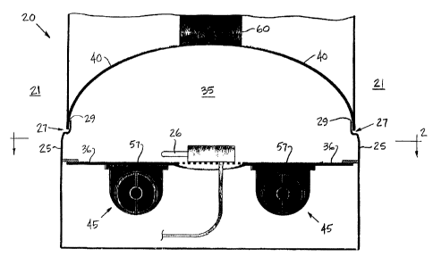
shown in
Fig. l, in a conventional manner, water heater 20 comprises combustion chamber
35 which
is in communication with exhaust flue b0. Also in a conventional manner,
exhaust flue 60
2o is in communication with ambient envimnment 21 surrounding water heater 20.
As shown in Fig. 4, fuel supply 22 and air supply 23 are introduced into
venturi 24. In one embodiment of this invention, the fuel and the air are
mixed within
venturi 24 so that a pre-mixed fuel and air mixture is supplied to burner
material 57 of
burner assembly 45. It is apparent that the fuel and the air can be pre-mixed
and/or can be
25 supplied to burner material 57 through any other nozzle or inlet or in any
other suitable
manner known to those skilled in the an of combustion.
As used throughout this specification and in the claims, the term fuel is
intended to relate to any gaseous fuel used in combustion, such as natural
gas, propane, and
other suitable combustible gases, or any suitable vaporized fuel. Also as used
throughout
3o this specification and in the claims, the term air is intended to relate to
atmospheric air or
any other suitable oxidant used to combust fuel.
6
.. _... .. .,._. .. . -,.~ ,~~ ", .* 05 , , r. ~~..~ . -... ".~, .. , ~.~ ~~
... _..___._ ___.__. ~ ...,.. __.... ~... n ,...._.. _. _ . _. _..._..
CA 02412926 2002-11-27
The fuel and air mixture passes through venturi 24 or any other suitable inlet
nozzle and is discharged from a flame holding device, such as burner material
57. A
combustion flame is preferably established on the surface of burner material
57.
As shown in Figs. 1 and Z, pilot 26 is used to ignite the fuel and air
mixture.
In one embodiment, pilot 26 is used only upon initial ignition of the fuel and
air mixture.
In a combustion system having two burner assemblies ~S, pilot 26 or another
suitable
ignitor can be strategically positioned to ignite the fuel and air mixture at
the surface of one
burner material 57, which can then be used to light the fuel and air mixture
at the surface of
another burner material 57. Once a combustion flame is established or
sustained, it is
to possible to extinguish pilot 26 if the combustion flame then ignites the
continuously
flowing fuel and air mixture.
In a pre-combustion state, for example before ignition, combustion chamber
35 is filled with a fluid Depending upon conditions, the fluid may include air
andlor
combustion products which remain within combustion chamber 35, such as shortly
after
shut down of water heater 20. Many conventional water heaters with premixed
burner
systems which operate with a combustion chamber that is substantially sealed
produce an
undesirable noise upon ignition due to the transient pressure pulse in the
combustion
chamber. Except for the communication with the flue stack and the inlet
nozzle, these
conventional water heaters are intentionally designed to achieve an otherwise
completely
2o sealed combustion chamber, for example to prevent additional combustion air
from
entering the combustion chamber.
Directly contrary to conventional water heater seated combustion chambers,
the method and apparatus of this invention, in addition to forming
communication with
exhaust flue 60 and venturi 24 or another suitable inlet nozzle, intentionally
forms
communication between combustion chamber 35 and ambient environment 21. In one
embodiment of this invention, pressure relief void 27 forms the intentional
communication
between combustion chamber 35 and ambient environment 21, such as shown in
Figs. I
and 11, through peripheral gap 29.
In one embodiment of this invention, upon ignition of the fuel and air
3o mixture within combustion chamber 35, a first portion of the pre-combustion
fluid is
discharged through pressure relief void 27 and a second portion of the pre-
combustion fluid
7
CA 02412926 2002-11-27
is discharged through exhaust flue 60. Pressure relief void 27 is preferably
sized large
enough to relieve an ignition pressure from combustion chamber 35 upon
ignition of the
fuel and air mixture and yet is sized small enough to prevent a combustion
flame from
passing through pressure relief void 27 during operational combustion of the
continuously
flowing fuel and air mixture.
An effective area of pressure relief void 27 can be sized and/or shaped
relative to an effective area of exhaust flue 60, so that a first pressure
drop or flow rate
across pressure relief void 27 is less than or significantly less than a
second pressure drop
or flow rate across exhaust flue 60. With such design, the ignition pressure
is adequately
relieved through pressure relief void 27. The pressure rclicf upon ignition
significantly
reduces undesirable noise associated with other conventional water heater
sealed
combustion chamber designs.
In one embodiment according to this invention, the effective area of pressure
relief void 27 can be sized as a ratio of the effective area of exhaust flue
60. The areas can
t 5 be changed, particularly relative to each other, to achieve different
ratios that vary
depending upon geometric and operational parameters of water heater 20. As an
example,
water heater 20 may have pressure relief void 27 formed by a 0.060 inch gap
about a 16
inches diameter combustion chamber 35, which operates in communication with a
4 inches
diameter exhaust flue 60. In this particular example, the dimensions result in
a ratio of
2o about 0.24 of the area of pressure relief void 27 over the area of exhaust
flue 60. However,
it is apparent that other suitable area ratios can vary significantly,
depending upon the
operating conditions and the geometry of water heater 20.
During operational combustion, such as the condition where the fuel and air
mixture continuously flows through burner assembly 45 and a combustion flame
is
25 established on the surface of burner material 57, relatively :little or no
combustion products
flow out of the combustion chamber through pressure relie~:Fvoid 27, and
relatively little or
no air flows into the combustion chamber through pressure relief void 27. If
desired, it is
possible to control a leakage rate of combustion products and/or air passing
through
pressure relief void 27 during operational combustion, such as by selecting a
different
3o effective area for pressure relief void 27.
8
CA 02412926 2002-11-27
As shown in Fig. l, peripheral gap 29 forms pressure relief void 27.
Peripheral gap 29 is preferably but not necessarily in a range from about
0.055 inch to
about 0.065 inch, preferably about 0.060 inch.
Spacer element 30 can be used to maintain peripheral gap 29, as shown in
Fig_ 1 between chamber wall 25 and vessel wall 40. Fig. 11 shows another
embodiment of
this invention where protuberance 32 extends from chamber wall 25 that
partially defines
combustion chamber 35, but protuberance 32 can also extend from the inner
surface of the
lower cdge of vessel wall 40. Protuberance 32 or another suitable spacer
element 30 can be
positioned at selected circumferential intervals about the periphery of
combustion chamber
35. For example, as shown in Fig. 13, protuberances 32 can be positioned at
eight
locations, each about 45 degrees apart, about the periphery of combustion
chamber 35. It is
apparent that any other suitable mechanical spacer element 30 can be used to
fix a size
and/or shape of pressure relief void 27.
In one embodiment according to this invention, burner material 57 is a self
supporting mat structure. The self supporting mat structure may comprise a
plurality of
ceramic fibers coated with a silicone carbide material or another suitable
material. The
ceramic fibers can be solidly welded together or otherwise fused into a rigid,
porous matrix.
The self supporting mat structure can be processed, for example as sheets
having a
thickness of approximately 0.10-0.15 inch. The porosity of the bulk material
may allow a
2o quantity of the fuel-air mixture to flew through the entire surface area.
Perforations
throughout the bulk material can be formed in a regular pattern to increase or
obtain the
suitable port loading, as defined by firing rate per square inch of burner
surface. A suitable
burner mat is offered by Schott Gas Systems, and is marketed as a Ceramat~
burner naat,
which has relatively low thermal conductivity, a rigid self supporting
structure, and low
thermal expansion, all of which provide a burner with stable combustion, low
emissions,
even radiation, fast reaction and a wide modulation range. A self supporting
mat structure
or another suitable burner material 57 can be mounted with respect to bottom
wall 36, such
as shown in Figs. 14 and 15.
Figs. 7 and 8 show difl"erent embodiments far mounting burner material 57
3o in burner assembly 45. Figs. 9 and 10 show plenum 53. In one embodiment,
the fuel and
9
CA 02412926 2002-11-27
air mixture are discharged from venturi 24 or another suitable inlet noazle,
into plenum 53.
The fuel and air mixture is then discharged from plenum 53 through burner
material 57.
Burner material 57 may be mounted to plenum 53 in burner assembly 45
using retainer 47. Insulator 61 can be positioned between bottom wall 36 and
burner
material 57, for example to reduce heat transfer between burner material 57
and both
bottom wall 36 and retainer 47, and to prevent combustion flames from burner
material 57
from quenching or attaching to edges of bottom wall 36.
Figs. 5 and 6 show one embodiment of water heater 20 having two burner
assemblies 45 mounted to bottom wall 36. Fig. 5 shows one burner assembly 45
attached
1o to bottom wail 36 and another burner assembly 45 detached from bottom wall
36.
In one embodiment of this invention, a mounting apparatus can be used to
releasably attach burner assembly 45 with respect to bottom wall 36. The
mounting
apparatus comprises flange 64, also shown in Figs. 3, 5, 14 and 15 formed
along the edge
of plenum 53 in burner assembly 45, such as shown in Fig. 4. Clip 50 is
attached to bottom
wall 36. It is apparent that clip SO can be welded, adhered, secured or
otherwise
mechanically connected to or with respect to bottom wall 36. In one
embodiment, as
shown in Fig. 5, clip 50 comprises base portion 52 and end portion 51 which is
offset from
or with respect to base portion 52. A transition between base portion 52 and
end portion 51
forms a shoulder. Figs. 14 and 15 show another embodiment of clip 50 attached
with
2o respect to bottom wall 36. In a mounted position of burner assembly 45 with
respect to
bottom wall 36, flange 64 limits movement of burner assembly 45 with respect
to bottom
wall 36, such as in a direction generally parallel to a longitudinal axis of
burner assembly
45.
In one embodiment, clip SO comprises slot 49, as shown in Fig. 5. In a
2s mounted position of banner assembly 45 with respect to bottom wall 36, seam
46 or another
suitable structure of burner assembly 45 is engaged within slot 49, for
example to limit
movement of burner assembly 45 in at least one direction 'with respect to
bottom wall 36,
such as in a direction which is generally transverse to the longitudinal axis
of burner
assembly 45.
3o A removable fastener is used to secure, attach or otherwise fasten an
opposite end of flange 64 to or with respect to bottom wall 36. Fastener 55
may be a
1U
CA 02412926 2002-11-27
screw, as shown in Figs. 5 and 14, or a catch or latch 62 as shown in Fig. 15.
- The catch or
latch 62 may attach within a shoulder area of bottom wall 36. As shown in Fig.
15, latch
62 can pivot with respect to bottom wall 36 about pivot 63, which can be a
pin, a rod or any
other suitable mechanical pivot device. The shoulder area can be formed by a
void within
bottom wall 36, a shoulder formed as an integral part of bottom wall 36 or a
shoulder
structure attached to bottom wall 36. It is apparent that any other suitable
removable
fastener can be used in lieu of either the screw or the catch or latch 62.
Flange 64, clip 50 and fastener 55 andlor latch 62 can be used to quickly
attach or detach burner assembly 45 with respect to bottom wall 36. This is
particularly
important when servicing a water heater. The design of this invention provides
easy access
for field installation andlor maintenance.
In an embodiment where two or more burner assemblies 45 are mounted
within combustion chamber 35, each burner assembly 45 is preferably positioned
at a
distance apart from each other to form catch area 38, such as shown in Figs.
2, 6, 16 and
l5 iT. In another embodiment where only one burner assembly 45 is mounted
within
combustion chamber 35, burner assembly 45 forms an annular shaped burner that
also
forms catch area 38, such as shown in Fig. 18. According to such embodiment,
the annular
shape can be replaced with a simple arcuate shape which does not necessarily
form a
complete circle. In either embodiment, catch area 38 can be used to gather or
collect debris
2o fallout, condensation or any other combustion product resulting from
operation of water
heater 20. Catch area 38 is preferably centrally located on bottom wall 36 but
may be
located in any other suitable position, depending upon the overall design and
structure of
water heater 20.
Figs. 16 and 17 show general arrangements of water heater 20, with two
2s burner assemblies 45 mounted at an angle with respect to bottom wall 36.
Access area 59
within a side wall defining combustion chamber 35, may provide easy access to
each
burner assembly 45, for installation andJor maintenance purposes.
While in the foregoing specification this invention has been described in
relation to certain preferred. embodiments thereof, and many details have been
set forth for
3o purpose of illustration, it will be apparent to those skilled in the art
that this invention is
11
CA 02412926 2002-11-27
susceptible to additional embodiments and that certain of the details
described can be
varied considerably without departing from the basic principles of this
invention.
12