Note: Descriptions are shown in the official language in which they were submitted.
CA 02413145 2002-11-28
Sid Car 134
PED~F. CAL SHEA~~AD
The Field: of the"~~vention
toooxl The present invention relates o a shear pad assembly adapted to be
positioned
between a rail car side frame pedeStaJ and the rail car roller bearing
adapter, and more
specifically, to such a shear pad assembly which includes an elastomer
positioned between
spaced upper and lowerplates and metal shims for reinforcing and
supporting~the elastomer.
[0002] Sh~r pads have Iong been known in the rail car art for use in
supporting the truck
side frames on the wheelsets. Initially, such shear pad assezttblies utilized
metal wear surfaces
which permitted limited latearal and longitudinal movement of the side frames
relative to the
,~
roller bearing adapteors positioned on the wheelsets. Subsequently,
elastomeric mountings took
the place of the metal wear surfaces to provide conuol fle7tibility in all
directions, particularly
for self steering rail car trucks.
[0003) U.S. Patent 5,23'7,933 improved the elastorneric mounting by the
addition of a single
metal shim which ex~ogenerally throughout the elastomer with the stated
advantage of
significantly increasing the service life of the shear pad. acre aspect of the
shear pad described
in. the '933 patent was to incise the thickness of the eiastomexic layer
adjacent its edge, as
comlaared with the thickness at the centeoc of the elastomcT to xeduce the
edge strains imposed
on the shear pad. This stated advantage, however; did not prove o be correct
in~that the
reduction of the elastomer thickness adjacent its center resented in
separation~of the elastomer
under prolonged loading The present invention providos an elastomer which is
more uniform
throughout the cross section of its thickness, resulting in more uniform shear
which has the
CA 02413145 2002-11-28
effect of spreading the shear load imposed on the pad more uniifoxmly across
the pad,
elvminaring the concen~cation of shear strain present in pads of the type
shown in the '933
patent.
~ummar?r of the Invention
j000~t] The present invention relates to shear pad assemblies for use in rail
car trucks to
support the side frames on the wheelset roller bearing adapters and more
specifically, to a
shear pad for the use described which has an improved reinforced elastomer.
[0005] A prvm~aiy purpose of the invention ;is to provide a shear pad assembly
as described
in which the elastomer, positioned between upper and: lower plates of the
shear pad assembly,
has a pair of spaced reinforcing shims.
j000f] Another purpose of the invention is ~to provide a shear pad assembly as
described in
which the elastomer is substantially uniform across its cross sectional area
to spread the shear
Load. relatively uniformly across the pad.
j000T1 Another purpose of the invention is to provide a shear pad assembly
which does not
concentrate the shear load at the center area of the pad.
j000~8] Another purpose of the invention is to provide a shear pad assembly
having shims to
stif~a the elastomer edges so that the overall stiff~aess of the pad is
geue~cally uniform.
j0409] Another purpose of the invention is to provide a shear pad assembly as
described in
which the ma~ciimua shear straui is zeduced, but.the overall sheaoc strain is
more uniform
throughout the thiclmess of the cross sectional area of the elastomer.
[OOIO] C3ther purposes will appear in the ensuing specification, drawings and
claims.
2
CA 02413145 2002-11-28
Brief Description of the D~awin~
[OOIIj The invention is illustrated diagrammatically in the following drawings
wherein:
[0012j Fig. 1 is a top plan view of a rail car truck illustrating the various
comgonenis
thereof;
(00~3j Fig. Z is a pa;rial exploded side view of the side frame; shear pad and
roller bearing
adapter forming apart of the rail car track of Pig. 1;
I0014j Fig. 3 is a top plan view of the shear pad;
(0015] Fig. 4 is a section along plane 4-r4 of Fig: 3; and
j0016J Fib. 5 is a front view of the shear pad assembly of Figs. 3: and 4.
Description of the Preferred Em'ho~litxle~nt
[001?J The present invention relates to an elastbmeric shear pad assembly for
use in
tuounting the side frames of a three-piece rail car truck to the roller
bearing adapters which
rest on the wheelsets. Such assemblies have long been known in the art and
they provide
control fleRibility inn all directions and have substantial advantage over
previously-used metal to
sliding surfaces or simiHar wear surfaces. Such advantages include reduced
lateral and
vertical shocks to the roller bearings, increased system dayp'tng, elimination
of wear between
the roller bear;ng adapter crown surface and the side fra~m~e pedestal jaw
roof, reduction in rail
car wheel wear, reduced rail wear, and improved life of the rraczc components.
[0018] U.S. Patent 5,237,933 discloses a shear pad asse~ly utilizing an
elasiomer between
the upper and lower plates of the assembly; with -the elastonaer being
reinforced by a metal
shim which extends generally midway through the elastamer. One of the
perceived advantages
of the shear pad assembly in the '933 patent was to decrease the compression
induced edge
3
CA 02413145 2002-11-28
strains by increasing the thickness of the elastomer toward its edges, while
reducing the
thickness of the elastomer in the centex of ~s shear pad assembly: The '933
patent stated that
au optimum ratio of the thicknesses of the edge of the elastomer to the center
is as high as 1.3
zo 1.
[00i9] Shear pad assemblies of the type shown in the '933 patent hare been
determine to
fail in the center under substantial shear load; particularly, there has been
noticed a separation
of the elastomer because the pad is thinnest at its center, but yet the rubber
or esastomer in the
center is doing the nwst work in resisting shear and compression loads. The
present invention.
substantially improves the shear pad assembly of the '933 patent by Providing
a generally
uniform thickness of they elastomer throughout its cross sectional area and
reinforcing the edges
by ate; independent shims, which are positioned along the pad edges and are
generally
parallel to tl~e diarection of the side frames. With this construction the
eIastomer is more
uniform throughout the cross section of the pad; with the result that. the
elastomer is more
nniforna in shear. This in e~'ect spzeads the shear load relatively uniformly
across the pad and
does not concxntrate it in the center. The elimination of shims in the center
of the shear pad
may we~en the center in stiffness, hut by stiffening the: edges, the overall
stiffness of the shear
pad is uniform across its width. The maximum shear strain is reduc~l; but the
shear strain is
more unifoxm thxxoughout its width, creating a, shear pad assembly which has a
substantially
extended life over those known in the prior art. : ~ =
[00?.Q] A further advantage of the shear pad assembly of the present invention
is that it is
thi~r is height by approximately 1/8" over that shown in the '933 patent and:
such a
reduction in height is important to raivroads, as it insures that there can be
a retrofit of the
4
CA 02413145 2002-11-28
shear pad assembly without having car couplers being non-aligned.
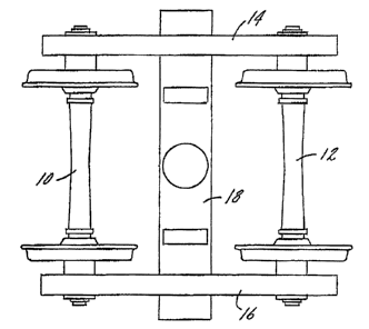
[QOZt] In Fig. 1 a conventional three-piece truck has wheelsets 10 and 12 upon
which axe
supported side frames 14 and 16. A bolster 38 connects the side frame, as is
conventional in
rail car trucks of this design. The side frames include side frame pedestals
20 with an opening
22 within which will be located the roller bearing adapter Z4 and a shear pad
assembly 26. It
should be understood that the portion of the side frame; roller bearing
adapter and shear pad
assembly shown in Fig. 2 will be gresent at each of the four corners of the
txuck shown in Fig.
l . The invention is particularly concerned with the shear pad assembly which
is illustrated in
detail in Figs. 3, 4 and 5.
[0022] The shear pad assembly includes an upper Plate 30, cmnventionally
formed of steel,
and having up-turned side edges 32, with the plate 30 forming a seat fox the
side frarue
pedestal 20.
jQ023J There is a lower steel plate 34; in the shrat pad assembly 26 which is
sgaced from the
upper plate 30 by a thickness 36: The lower plate 34 witl have down tuned
projections 38 at
ogposite sides thereof, as particularly illustrated is Fig. 5. The space 36
will be frilled by a
suitable elastomer 42 wl3ich will both fill the space 36 and substantially
encapsulate both the
upper plate 30, its up-anrned edges 32, the lower plate 34 and its down-turned
edges 38.
Elastomers to perform this fi~nccioa are well known in the art.
[0024? There are a pair of spaced metal. shims 4f? embedded in the space 36
which is filled
by the elastom~e~r, with the shims being essentially parallel to each other;
and parallel to the
direction of the side frames 14 and I6. The shims are identical in width,
thickness and length
and each will be embedded within the elastomer'42: Each shim will have its
outer edge 44
CA 02413145 2002-11-28
outside of the ap-turned edges 32 and inside of the down-turned edges 38.
Directly adjacent
and slightly inside of the outer edge 44 of each shim there is a concavity 46
in the ~ elastomez.
Similarly, there is a concavity 48 is the elastamer directly above the shim
and generally where
the eIastomer joins tbEat portion of it which encapsulates the up-turnal edges
32. Such
concavities or contours are useful in minimizing the compression induced edge
stzains in the
shear pad assembly and are shown in the '933 patent.
[OQ?.53 Of importance is the fact that the elastomer 42 is generally uniform
in thickness
throughout its cross section area. This provides a more uniform resistance to
shear because
of the uniform thickness of the elastomeiric material The shims 40 stiffen the
edges of the
shear pad asserably to resist compression. Althoughthe center of the pad map
be slightly
weakened in stiffness, the additional stiff -erring: P~rvided at the edges by
the shims provide a
more uaifoxm stiffness across the cross section of the pad. The maximum shear
strain of the
pad assembly may be rednced-over that shown is prior art asseanblies for the
same function,
but the overall shear strain is more unifoxm, zesulting: in a shear pad
assembly having
substaatiaIly used: life.
[Q026~ The shear pad assembly will be thinner than that of the prior art
because of the
absence of a shim in the center of the eiastomer: - This reduced thictaaess;
by approximately
0.120" is very advantageous in retrofitting the shear pad assembly to existing
rail cars, as it
reduces the potential for non-aligned couplers: . ~.
[802?j Whereas the prefl form of the imrention has been shown and described
herein, it
should be realized tl:aat there may be many modifications, substitutions and
altexations thereto.
6