Note: Descriptions are shown in the official language in which they were submitted.
CA 02413266 2005-12-12
2358-1817
Title of the Invention
RELEASABLE LOCKING DEVICE
Technical Field of the Invention
This invention pertains to a releasable locking
device, which has an intended use at a beam-to-column
connection in a storage rack, such as a pallet rack. This
invention also pertains to a storage rack, such as a pallet
rack, which comprises the releasable locking device.
Background of the Invention
In a storage rack, it is common to connect a beam
to a column via a flanged member having a side flange welded
to one end of the beam and a front flange, from which
fasteners having inner heads project into similarly shaped
apertures in a front wall of the column. Commonly, the
apertures are shaped so that the inner heads of the
fasteners can pass through upper regions of the apertures
but not through lower regions of the apertures. Thus, the
flanged member must be lifted to permit the inner heads of
the fasteners to pass through upper regions of the
apertures.
At an early date, it was realized that if the beam
or the flanged member were struck by an object, such as a
pallet, as the object was being lifted, the object could
dislodge the flanged member from the column unless a
latching or locking device was provided. Various latching
or locking devices have been disclosed for latching or
locking beams to columns.
Many prior patents disclose such latching or
locking devices at beam-to-column connections in storage
racks. One example is disclosed in United States
1
CA 02413266 2005-12-12
23158-1817
Patent 5,624,045, in which the fasteners are described as
connecting pins. Other examples, which employ spring-biased
pins, are disclosed in United States Patent No. 3,330,583,
in United States Patent No. 4,074,812 and in United States
Patents No. 5,938,367 and No. 6,203,234, United States
Patent No. 6,155,441, United States Patent No. 6,230,910,
and United States Patent No. 6,352,164.
Summary of the Invention
This invention provides a releasable locking
device comprising a housing, a locking pin, and an outer
sleeve, which a user can pull to release the releasable
locking device. The housing has a lateral wall, which has
an elongate slot, an outer end, and an inner end. The
housing has an end wall closing the outer end and is open at
the inner end. The locking pin, which has an internal
portion movable inside and along the lateral wall of the
housing and which has a locking portion, is movable between
a retracted position wherein the internal portion of the
locking pin is spaced from the end wall of the housing by a
comparatively lesser distance and an extended position
wherein the locking portion of the locking pin extends from
the inner end of the housing and wherein the internal
portion of the locking pin is spaced from the end wall of
the housing by a comparatively greater distance.
The locking pin is biased, as by a coiled spring
acting between the end wall of the housing and the internal
portion of the locking pin or by an elastomeric member
acting therebetween, toward the extended position. The
outer sleeve, which is movable outside and along the lateral
wall of the housing, is connected to the locking pin via a
2
CA 02413266 2005-12-12
23158-1817
connecting pin extending from the locking pin, through the
elongate slot. The outer sleeve is connected to an end of
the connecting pin.
2a
CA 02413266 2002-12-02
Preferably, the elongate slot has two closed ends, which limit movement of
the locking pin between the retracted and extended positions. Preferably, the
elongate slot is one of two parallel slots, each slot being located on an
opposite
side of the lateral wall of the housing, the connecting pin extending through
the
locking pin, through each slot, and being connected to the outer sleeve at
each end
of the connecting pin. Preferably, the outer sleeve has a flange to facilitate
pulling
of the outer sleeve to move the locking pin toward the retracted position.
This invention also provides a storage rack comprising a column, a beam,
and a releasable locking device, as described above. The column has a vertical
array of fastener-receiving apertures, each having an upper region and a lower
region and each having a margin, and a beam having an end flange, to which
plural fasteners are mounted. Each fastener has a distal portion adapted to be
inserted into the upper region of an associated one of the fastener-receiving
apertures and to engage an inner margin of the same one of the fastener-
receiving
apertures, at the lower region of the associated one of said apertures, so as
to
prevent the distal end from being withdrawn unless and until the distal
portion is
elevated.
Preferably, each fastener is a connecting pin having a distal head and each
fastener-receiving aperture has a keyhole or teardrop outline, as exemplified
in
United States Patents No. 5,624,045, supra. A connecting pin having a distal
head
may be also called a stud. Alternatively, each fastener has a distal hook and
each
fastener-receiving aperture is a vertical slot. Herein, therefore, all
references to a
connecting pin having a distal end are intended to refer either to a
connecting pin
having a distal head or to a connecting pin having a distal hook.
-3-
CA 02413266 2002-12-02
In the storage rack provided by this invention, the housing of the releasable
storage device is mounted to the end flange and opens at the inner end of the
housing to a hole in the end flange. The hole is aligned with the upper region
of a
selected one of the fastener-receiving apertures, whereby, in the extended
position,
the locking pin extends through the hole in the end flange, into the upper
region
aligned with the hole.
Brief Description of the Drawings
Figure 1 is a simplified, fragmentary, isometric view of a storage rack, such
as a pallet rack, embodying this invention and comprising a column, an upper
beam and a lower beam, and, where each of the upper and lower beams is
connected to the column, a releasable locking device embodying this invention.
Figure 2, on a larger scale, is a detail taken from a region indicated in
Figure l,
where the upper beam is connected to the column.
Figures 3, 4, 5, and 6, on a larger scale compared to Figure l, illustrate the
releasable locking device, apart from the storage rack. Figure 3 is a
perspective
view. Figure 4 is a front elevation. Figure 5 is a side elevation, which is
taken
from the right side of the releasable locking device, as shown in Figure 4,
and in
which a locking pin is illustrated in an extended position. Figure 6 is a side
elevation, which is taken from the right side of the releasable locking
device, as
shown in Figure 4, and in which the locking pin is illustrated in a retracted
position.
Figures 7 and 8, on a smaller scale compared to Figures 3, 4, 5, and 6, are
fragmentary cross-sections taken along a vertical pane, through an end flange
of
the upper beam, through the column, through two connecting pins, and through
the
releasable locking device. In Figure 7, the locking pin is illustrated in the
-4-
CA 02413266 2002-12-02
extended position. In Figure 8, the locking pin is illustrated in the
retracted
position.
Detailed Description of the Illustrated Embodiment
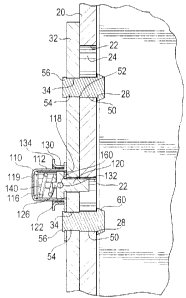
As illustrated in Figure 1, a storage rack 10 comprises a column 20, an
upper beam 30 and a lower beam 40, and, where each beam 30, 40, is connected
to
the column 20, a releasable locking device 100 embodying this invention. The
column 20 has two vertical arrays of fastener-receiving apertures 22, each
aperture
22 having an upper region 24 and a lower region 26 and each aperture 22 having
an inner margin 28. The beams 30, 40, are similar and are connected similarly
to
l 0 the column 20.
As illustrated in Figures 1, 2, 7, and 8, the upper beam 30 has an end flange
32, to which plural connecting pins 50 are mounted. Each connecting pin 50 is
stepped so as to define a shoulder 52 and so as to define a proximal portion
54,
which is passed outwardly through a hole 34 in the end flange 32, until the
shoulder 52 bears against an inner margin 36 of the hole 34, whereupon the
proximal portion 54 is swaged, as a rivet is swaged conventionally, so as to
provide a proximal head 56 on the proximal portion 54 of said connecting pin
50.
Each connecting pin 50 has a distal head 60, which is adapted to be inserted
into
the upper region 24 of an associated aperture 22 and to overhang the inner
margin
28 of the associated aperture 22, at the lower region 26 of the associated
aperture
22, so as to prevent the distal head from being withdrawn unless and until the
distal head 60 is elevated until the distal head 60 is aligned with the upper
region
24 of the associated aperture 22. Thus, except that a selected one of the
connecting pins 50 is used also to mount the releasable locking device 100 in
a
manner to be later described, the upper beam 30 is mounted to the column 20 in
a
-5-
CA 02413266 2002-12-02
manner disclosed in United States Patents No. 5,624,045 and No. 5,713,367,
supra.
The releasable locking device 100 comprises a housing 110, which defines
an axis, a locking pin 120, and an outer sleeve 130, which a user can pull to
release the releasable locking device 100. The housing 110 has a tubular,
lateral
wall 112, which def nes an axis, an outer end 114, which is closed by an end
wall
116, and an inner end I 18, which is open. The locking pin 120, which defines
an
axis and is coaxial with the housing wall 112, which has a flanged portion 122
movable inside and along the lateral wall 112, which has a locking portion 124
extending inwardly, and which has an axial stub 126 extending outwardly, is
movable between a retracted position and an extended position. In the
retracted
position, the locking portion 124 extends from the open end 118 of the housing
I 10 by a comparatively lesser distance, by which the flanged portion 122 is
spaced
from the housing wall 116. In the extended position, the locking portion 124
extends from the open end 118 of the housing 110 by a comparatively greater
distance, by which the flanged portion 122 is spaced from the housing wall
118.
The locking pin 120 is biased, by a coiled spring 140 piloted around the
axial stub 126 and acting between the housing wall 116 and the flanged portion
122, toward the extended position. An elastomeric member (not illustrated)
acting
between the housing wall 116 and the flanged portion 122 may be instead used
to
bias the locking pin 120 toward the extended position. The outer sleeve 130 is
fitted around the housing wall 1 12 so as to be axially movable outside and
along
the housing wall 112. The housing wall 112 has two elongate, parallel slots I
50,
each having a closed, inner end 152 and a closed, outer end 154. A cross pin
160
extends through a hole 162 in the locking pin 120, through the flanged portion
-6-
CA 02413266 2002-12-02
I 22. Each end 164 of the cross pin 150 extends through one of the elongate,
parallel slots 150 and fits with an interference fit into a hole 132 in the
outer
sleeve 130 so as to connect the outer sleeve 130 to the locking pin 120. The
closed ends 152, 154, of the parallel slots 150 limit movement of the cross
pin
160, so as to limit movement of the locking pin 12U between the retracted and
extended positions. Thus, as the outer sleeve 130 is moved along the housing
wall
112, the latching pin 120 is moved with the outer sleeve 130.
The housing I I 0 has an integral, lower tab I 70, which has a hole 172 to
accommodate the proximal portion 54 of the selected one of the connecting pins
50, before the proximal portion 54 thereof is swaged, as a rivet is swaged
conventionally, so as to provide a proximal head 56 on the proximal portion 54
thereof. The lower tab 170 is arranged to align the locking portion 124 of the
locking pin 120 with the upper region 24 of the associated aperture 22. Thus,
the
selected one of the connecting pins 50 not only coacts with the other
connecting
pins 50 to mount the upper beam 30 to the column 20 but also mounts the
releasable Locking device 100 to the end flange 32 of the upper beam 30 so
that,
when the upper beam 30 is mounted to the column 20, the locking portion l 24
of
the locking pin 120 snaps automatically into the upper region 24 of the
associated
aperture 22.
The outer sleeve I 30 has an outer flange 134, which facilitates pulling of
the outer sleeve 130 to move the locking pin 120 toward the retracted
position,
whereby to withdraw the locking portion 124 of the locking pin 120 from the
upper region 24 of the associated aperture 22. Thus, a user pressing the thumb
of
one hand against the housing wall 116 and pulling on the outer flange 134 with
the
_7_
CA 02413266 2002-12-02
next two fingers can pull the locking pin 120 toward the retracted position,
whereby to release the releasable locking device 100.
Although a releasable locking device embodying this invention has an
intended use at a beam-to-column connection in a storage rack, such as a
pallet
rack, a releasable locking device embodying this invention may prove to have
other similar and dissimilar uses.
_g_