Note: Descriptions are shown in the official language in which they were submitted.
CA 02413306 2002-12-02
WATERTIGHT D00R OR WINDOW FITTING, PARTICULARLY FOR CIVIL
USE
1 The object of this invention is a watertight type door or
2 window fitting.
3 The invention is used particularly, but not exclusively, in the
4 sector involved with the dressing of buildings, either new
S constructions or pre-existing buildings subject to maintenance
6 interventions.
7 FOREWORD
g Door and window fittings for buildings are well-known. Their
9 main aim is to keep the internal temperature of the building at an
optimum levei,~whatever the climatic conditions on the outside.
11 One of the main functions of the companies involved in this
12 activity is, therefore, to guarantee that the windows and doors
13 offer efficient protection against, thermal variations, that is to say,
14 to construct a barrier against inclement weather. However, if on
the one hand the door and window fittings generally used today
I
CA 02413306 2002-12-02
D'AGOSTINI GROUP Riv. Castelvecchio 6 TREVISO G. D'Agostini
1 offer effiicient protection against temperature variations and
2 against the wind, they are not as efficient, or are certainly less
3 efficient, against water entering into the building. This is not true in
4 the case of rainwater, since it is a spasmodic event and because
the quantity of water which hits against the door or window is
6 relatively small, especially in those cases where the doors or
7 windows are located in areas or recesses which are more or less
8 always protected. On the other hand, there is not sufficient
9 protection in those cases, albeit less frequent, in which the buildings
are hit by natural disasters such as floods or other such events,
11 such as high tides which occur in nearby Venice.
12 It appears quite clear, therefore, that door and window
13 fittings currently used and installed in buildings are insufficient in
14 guaranteeing that water does not Peak or seep through them, or
even leak or seep around their sides if we take into consideration
16 the size of the gaps around the doors and windows due to
17 irregular jointing surfaces. Even the most advanced types of seals
18 available are unable to solve the problem, since the pressure
19 exerted on them is proportional to the depth of the water. As a
result, since the events considered may be quite violent, such as
21 river floods, the amount of water involved is so high that any
22 traditional barrier or protection will be inadequate.
23 There are a number of solutions which may be adopted to
24 avoid water leaking into the building. One such example is
2S US38fi1081 (Maskell), which employs a «U»-shaped frame which is
2
CA 02413306 2002-12-02
D'AGOSTINI GROUP Riv. Castelvecchio 6 TREVISO G. D'Agostini
1 fixed to the walls on the outside of the building, in this case the
2 sides of the lower part of a door. The said frame is made up
3 basically of <(U»-shaped straight segments with sealing means,
4 which guide and hold in place a panel of impermeable material
inserted from above as and when required and which, once the
6 emergency is over, may be easily removed. The solution described is
7 not very practical, both for the limit in height of the panel and for
8 its functionality and appearance.
9 In 1980, the Belgian patent BE0882294 (S.t.r.v.) proposed a highly-
efficient solution for insulation purposes, to be used for doors,
11 windows and other fittings. From a practical point of view, there is
12 a seat around the perimeter of the framework which fits into the
13 hole where the fitting is to be installed, with a tubular seal similar to
14 an inner-tube inside the said seat. The said seat and seal couple
against the edge of the framework of the mobile part of the fitting
16 so that, when it is closed, and as and when required, a fluid may be
17 injected into the inner-tube, with the pressure of the fluid gradually
18 expanding the seal until at presses against the edge of the closed
19 mobile part.
This solution, even though it is more efficient than the
21 previous one, has certain limits which, to sum up briefly, are its
22 insufficient seating properties due to the fact that it is the profile of
23 the expanded tubular portion which presses against edge of the
24 framework of the fitting when it is in a closed condition. When there
is a large amount of water to be held back, leaking is still a
3
CA 02413306 2002-12-02
D'AGOSTINI GROUP Riv. Castelvecchio 6 TREVISO G. D'Agostini
1 problem, which causes considerable damage on the inside of the
2 building, and above all the solution is not suitable for other uses. A
3 further development is described in patent N° FRZ723137 (Berard),
4 in which a shaped profile in rubber is placed between the tubular
seal and the edge of the framework of the fitting against which the
6 mobile part is closed. In this example, the said profile is shaped on
7 one side in order to hold the inflated tubular element and is flat on
8 the other, with this latter side which presses against the perimeter
9 of the framework. More recent solutions, such as GB2333118
(MacLean), use the same concept as FR2723137 (Berard), which
11 attempts to guarantee a more efficient ~ seal by working on the
12 conformation of the tubular seal, which in this case does not have
13 the element in rubber, and presses with a pyramidal, protruding rim
14 against the framework.
Amongst the most noteworthy solutions, there are also
16 proposals which use the concept of a device to inflate an inner-tube
17 located around the perimeter of the window or door fitting. This is
18 the case with US4706413 (James) which operates in conjunction
19 with a sensor, in this case a smoke detector, which sends a signal
to a supply of compressed air if smoke is detected, and which
21 inflates the inner-tube located around the perimeter of the said
22 door or window fitting.
23 THE MOST RECENT PRECEDENTS
24 In DE19615055 (Winiger), there is the description of a fitting
for sealing purposes, similar to the one described above, which has
4
CA 02413306 2002-12-02
D'AGOSTINI GROUP Riv. Castelvecchio 6 TREVISO G. D'Agostini
1 an inflatable, tubular element located around the perimeter of the
2 fitting, and which is in contact with the sides of the opening made in
3 the wail. Going further into detail, the said fitting has a frame-type
4 rim which faces the outside and which, when the fitting is in a closed
S condition, overlaps the external side of -the wall in correspondence
6 with the opening. As a result, the inflatable, tubular element is
7 alongside the said rim and, when it is pressurised, it presses against
8 the sides of the opening and against the internal side of the rim.
9 1n the European patent N° EP0731245 (Schmitz), there is the
description of a similar solution. The main difference is that the
11 tubular, sealing element, which is located around the perimeter of
12 the fitting, only presses against the edge facing the framework.
13 Furthermore, it is located at a certain distance from the rim, which
14 simply overlaps the wall, along the edge of the opening for the
fitting.
16 In GB2342377 (Price), there is a proposal to include a
17 container of compressed air, which may be connected by means of
18 two inflatable, tubular elements located around the fitting.
19 Finally, in DE3329829 (1_eu), the major difference is that the
slot for the inflatable, tubular element is located in the framework
21 for the fitting itself, rather that in the outer framework. Also, the
22 said tubular element has a fitting with a valve, to be connected to a
23 container for compressed air. The said valve is controlled by a
24 sensor which detects the presence of water, and which is positioned
5
- CA 02413306 2002-12-02
D'AGOSTINI GROUP Riv. Castelvecchio 6 TREVISO G. D'Agostini
1 close to the window or door fitting, on the outside face where it is
2 installed.
3 DRAWBACKS
4 The drawbacks, with reference to the solutions described
above, are as follows.
6 Firstly, door and window fittings currently used for civil
7 purposes need to be optimised to avoid that, when necessary, and
8 also in conditions such as high pressure, water may teak through.
9 The sealing of the said fittings relies entirely upon the tubular seal
which inflates when injected with fluid under pressure. As a result,
11 because the seal is directly subject to pressure in a number of
12 points, it is often insufficient to guarantee a tight seal. This
13 drawback is even more felt if the pressures which such systems
14 may have available is taken into consideration. Going further into
detail, since only a iow pressure is used to keep the inner-tube
16 inflated, it is particularly vulnerable, since a change in the depth of
17 the water or the force of the water which laps against the fitting
18 may be sufficient to lead to sea! failure.
I9 For this and other reasons, alternative proposals must be
singled out which, at the same time, represent a technical progress
21 compared with the solutions currently available.
22 BRIEF DESCRIPTION OF THE INVENTION
23 These and other aims are achieved by means of this invention
24 according to the characteristics in the attached claims, by solving
the problems described by means of a watertight door or window
6
CA 02413306 2002-12-02
D'AGOSTINI GROUP Riv. Castelvecchio 6 TREVISO G. D'Agostini
1 fitting for civil use, which includes a container with a reserve of
2 compressed air. The said container, in conjunction with a valve
3 positioned along the line and with a sensor to detect the presence
4 of water, is connected to at least one seal with a tubular chamber.
The said seal is positianed around the perimeter of the outer
6 framework, against which the mobile framework of the flitting, which
7 opens only towards the autside of the building, closes.
8 ADVANTAGES
9 In this way, through the creative contribution of the system,
which leads to an immediate technical progress, various
1I advantages are achieved.
12 With reference to the state of the art, and compared with
13 proposal N° US3861081 (Maskell), the water-tightness of the fitting
14 does not depend on the height of the panel and, since it does not
use the panel concept, it is more functional and mare attractive.
16 As far as the Belgian patent BE0882294 (S.t.r.v.), patent
17 FR2723137 (Berard) and patent GB2333118 (MacLean) are
18 concerned, this proposal optimises the water-tightness by
19 combining the action of an inflatable seal with the mechanical
resistance of the rim on the outer framework against which the
21 mobile framework closes. From a practical point of view, this
22 results in an increase in the efficiency of the seal, which adapts itself
23 according to the amount of water present on the outside.
24 As far as US4706413 (James), DE19615055 (Winiger),
EP0731245 (Schmitz), GB2342377 (Price), and DE3329829 (Leu)
7
CA 02413306 2002-12-02
D'AGOSTINI GROUP Riv. Castelvecchio 6 TREVISO G. D'Agostini
1 are concerned, the main difference with the solution proposed is the
2 position of the rim, which means that the mobile framework may
3 only be opened towards the outside, and the position of the seal,
4 which is positioned class to the rim. This leads to a more efficient
sealing against water leakage, and they work in conjunction with the
6 system which detects the presence of water on the outside and
7 which communicates with the fluid-feed system to guarantee a
8 rapid intervention.
9 These and other advantages are anything but negligible, and
lead to a product which is manufactured with a high level of
11 technology, which is functional and extremely reliable, especially
12 under adverse conditions.
13 Other advantages will be shown in the following detailed
14 description and drawings of a preferred application of the system,
the particulars of which are to be considered merely an example,
16 and not a limitation.
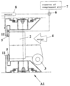
17 CONTENTS OF THE DRAWINGS
18 Fig. 1 is a transversal, sectional outline of a watertight fitting
19 under static conditions, in conjunction with a water-detection
system which activates the fluid-feed device.
21 Fig. 2 is another transversal, sectional view of the fitting
22 illustrated in Fig. 1, in a simplified, operational condition.
23 Fig. 3 is another transversal, sectional view of a second type
24 of fitting, but without the water-detection system which activates
s
CA 02413306 2002-12-02
D'AGOSTINI GROUP Riv. Cas~telvecchio 6 TREVISO G. D'Agostini
1 the fluid-feed device, and with a different position and conformation
2 of the inflatable seal.
3 DESCRIPTION OF AN APPLICATION OF THE fNVENTiON
4 This solution refers to a watertight door or window fitting,
particularly for civil use. doing into detail, a fitting of type (A1, A2)
6 is made up of an outer frame (7 ) which is fixed to a wall around the
7 perimeter of the opening to be sealed off. On one side of the said
8 outer frame (1 ), there is a symmetrical rirn similar to a frame (11 ),
9 positioned so that it protrudes towards the inside of the building.
!n this case, on the external side of the fitting (A1, A2), there
11 is the mobile part or frame (2) of the fitting. It has at least one
12 hinge (3) and opens outwards only, that is, against the pressure of
I3 the water (4) that may be present. When the said frame (2) is in a
14 closed position, its edge (21 ) presses in correspondence with at
least one seal, which has a closed, tubular chamber (5) which may
16 be inflated. In this case, the seal (5) is positioned between the
17 internal side of the rim (11 ) of the outer frame (1 ) and the said
18 edge (21 ) of the frame, in order to guarantee at least a minimum
19 sealing effect, even if no fluid has been injected into it.
Regarding the conformation of the seal with the inflatable
21 chamber (5), in the fitting (A1 ) proposed, there is a portion on one
22 side (51 ) for fixing it to the outer frame (1 ). In this case, there is a
23 channel (12) towards the inside of the outer frame (1 ) and
24 alongside the rim (11 ), where the rear portion (51 ) of the seal (5)
is inserted. The front portion (52), which has a !ip-type formation
9
CA 02413306 2002-12-02
D'AGOSTINI GROUP Riv. Castelvecchio 6 TREVISO G. D'Agostini
1 sticking out, sits up tight against the rim (11 ), and is connected to
2 a reserve of compressed air (7) by means of a valve (6) positioned
3 along the feed line. In one case, the reserve of compressed air (7)
4 consists of a container located inside the outer frame (1 ) or in a
dedicated space in the wall, so that it may be easily inspected.
6 Finally, there is a sensor (8) located outside the fitting (A1,
7 A2), which is used to detect the presence of water (4). The said
8 sensor (8) is connected to the valve (6), and when the said sensor
9 (8) detects the presence of water (4), it sends an impulse to the
valve (6) so that, when it opens, the pressurised air held in the
11 container (7) flows into the chamber in the front portion (52) of
12 the seal (5). The seal (5) expands, so that it presses uniformly
13 against the edge (21 ) of the frame (2), At the same time, the
14 pressure of the water itself, which presses the mobile frame (2)
1S against the seal (5) and against the rim (11 ) of the outer frame
16 (1 ), helps to increase the efficiency of the seal.
17 Fig. 2 illustrates the same fitting as in Fig. 1, but with the seal
18 (5) in operating conditians. In particular, this shows the case in
19 which the sensor (8) or ether detection means, or even by means
of a manual intervention, the presence of water has been detected
21 which, as described previously, sends an impulse to the valve {6).
22 When the barrier is no longer required, the chamber (52), by taking
23 up its original shape, sends the air contained inside back through
24 the valve (6), which is a two-way type, and towards the container
zs {7).
to
' CA 02413306 2002-12-02
D'AGOSTINI GROUP Riv. Castelvecchio 6 TREVISO G. D'Agostini
1 In the solution illustrated in Fig. 3, there is a second proposal
2 for a fitting. Going into detail, compared with the first proposal, the
3 fitting (A2) has the seat (5) with the inflatable chamber (52) in a
4 different position. In this case, the rim (11 ) is formed in a different
way on the internal side, in order to create a longitudinal seat (111 )
6 where the seal (5) may be inserted and held in place. In this case,
7 the seal (5) has a base (53) with a groove on each side, into which
8 the longitudinal edges of the opening (111 ) are fitted.
9 Finally, in a preferred solution, the fitting, which may be either
type (A1 ) or type (A2), is made in such a way that the seal (5)
11 may be inflated continuously and independently from the presence
12 of water on the outside. Going further into detail, the chamber (52)
13 of the seal (5) is injected with fluid, for example with compressed
14 air, every time that the frame (2) is closed against the outer frame
(1 ). In this way, the fitting no longer requires any kind of sensor (8)
16 to detect the presence of water, thus keeping the inside of the
17 building watertight.
m