Note: Descriptions are shown in the official language in which they were submitted.
CA 02413345 2002-12-19
WO 02/29353 PCT/AU01/01252
-1-
DELIVERY OF EMULSION EXPLOSIVES
The present invention relates to the delivery of emulsion explosives
compositions,
including non-sensitised emulsions for explosives' use. In particular, the
present invention
relates to an apparatus and process for charging a blasthole with an emulsion
explosives
composition and/or, for example, for transferring emulsion explosives
composition from
one container to another.
The delivery of many types of explosives is typically conducted by the use of
pumps such
as piston pumps and progressive cavity pumps because of the relatively high
pressures
usually required. However, the passage of emulsion explosives compositions
through these
pumps, even in non-sensitised condition, is potentially hazardous as failures
in the
pumping mechanisms can lead to excessive heat or pressure being applied to the
material
and can cause accidental explosion.
It has been proposed to alleviate these disadvantages in some circumstances by
delivering
emulsion explosives compositions pneumatically. Pneumatic loading of one of
the most
common forms of commercial explosives, ammonium nitrate/fuel oil mixtures
(ANFO), is
well known. ANFO is a dry explosive with good flow qualities and delivery into
a
borehole is commonly performed through a valued outlet in the bottom of a
pressure vessel
containing the ANFO at a pressure in the range of 200 - 600 KPa.
As described in International Patent Application WO 98/10237, adopting a
similar
proposal for emulsion explosives compositions can remove control in the amount
of
material loaded into the borehole and produce undesirable splash and waste at
the required
pressures. In WO 98/10237 these disadvantages are proposed to be alleviated by
adopting
an incompressible liquid such as water to pressurise a substantial volume of
the emulsion
explosives composition in a pressure kettle.
The use of water for charging blastholes with emulsion explosives compositions
is
undesirable because the water can be absorbed into the emulsion, with even
small absorbed
amounts reducing the blasting energy of the emulsion, increasing the critical
diameter and
CA 02413345 2002-12-19
WO 02/29353 PCT/AU01/01252
-2-
reducing the sensitivity of the emulsion. Additionally, large volumes of
potentially
contaminated water must then be disposed of.
The pneumatic charging of emulsion explosives compositions is also described
in British
Patent Application GB 2204343. In this proposal, a non-explosive base emulsion
and a
gassing solution axe transferred into a loading hose from respective hoppers
by means of
compressed air. They are mixed in a homogeniser at an outlet end of a lance
connected to
the hose. Prior to being mixed together the gassing solution surrounds the
base emulsion in
the hose to lubricate the passage of the base emulsion therethrough and allow
lower
pressures to be used in the hoppers. The supply of compressed air to the
hoppers, and
therefore the delivery of emulsion explosive from the lance, is controlled by
a shut-off
value on the lance which is biased into its closed condition. Thus an operator
adjacent to
the blasthole collar must manually hold the shut-off valve open.
It is suggested in GB 2204343 that it is preferred to use respective pumps for
feeding the
base emulsion and gassing solution into the loading hose, in place of
compressed air in the
hoppers.
International patent application WO 97/48966 also proposes the pneumatic
delivery of
emulsion explosives compositions to boreholes. The arrangement described is
similar to
that in GB 2204343 except that lubrication of the material being delivered is
provided by
an annular stream of water around the material in the delivery hose.
Additional ways of
maintaining relatively low extrusion pressures are described, including
keeping the internal
diameter of the delivery hose and associated components as large as possible.
Compressed
air pressures of about 240 and 550 KPa are described.
One of the difficulties associated with all of the above proposals for
delivering emulsion
explosives compositions pneumatically remains the control of the amount of
material
delivered, given the compressibility of the gas.
The metered delivery of explosives using pneumatic discharge is described in
US patent
specification 5,811,911 which proposes the use of complex metering means,
control means
CA 02413345 2002-12-19
WO 02/29353 PCT/AU01/01252
-3-
and a programmable controller. The metering is then performed by timing the
flow or
delivery of the explosives.
As described in the aforementioned patent specifications, with conventional
pneumatic
delivery of emulsion explosives compositions, the whole inventory of the
composition
available for delivery is pressurised leading to complex apparatus whose use
underground
is restricted to qualified personnel. The pressurised vessels from which the
composition is
delivered are also subject to strict controls leading to additional expense
both in
manufacturing them and in maintaining them.
It is an object of the present invention to alleviate these disadvantages of
previous
proposals.
According to the present invention there is provided apparatus for delivering
emulsion
explosives composition, the apparatus comprising an unpressurised vessel for
storing or
supplying the composition to a pressure chamber, a sealable inlet to the
chamber for
charging the chamber with emulsion explosives composition from the vessel, an
outlet
from the chamber, and a fluid pressure opening to the chamber for applying a
discharge
pressure to the chamber for delivering emulsion explosives composition in the
chamber
through said outlet, wherein the apparatus has a maximum operating pressure
and a
volume of the pressure chamber such that it has a pressure volume (pV) value
of less than
10 MPaL.
The present invention also provides a process for the delivery of emulsion
explosives
composition comprising the steps of:
a) storing a supply of the composition in an unpressurised vessel;
b) charging a pressure chamber with emulsion explosives composition from the
vessel
through a sealable inlet to the chamber; and
c) applying a discharge pressure to the chamber to discharge emulsion
explosives
composition in the chamber through an outlet from the chamber;
CA 02413345 2002-12-19
WO 02/29353 PCT/AU01/01252
-4-
wherein the discharge pressure and the volume of the pressure chamber are such
that the pressure chamber has a pressure volume (pV) value of less than 10
MPaL.
As used herein, the term "emulsion explosives composition" shall be understood
to include
sensitised emulsion explosives, base emulsions for emulsion explosives, that
is
unsensitised emulsion phases, as well as slurry and melt-in-fuel explosives.
The apparatus
and process of the invention may be used for base emulsions for water-in-oil
emulsion
explosives, optionally including particulate matter such as ammonium nitrate
prills. The
apparatus and process are most commonly used to deliver a pre-sensitised
composition,
that is, a base emulsion premixed with a sensitising agent, such as glass
microballoons, to
produce an emulsion explosive. These types of emulsion explosives are well
known to
those skilled in the art. The base emulsion tends to be too low in viscosity
to retain gas
bubbles which are commonly used in chemical gassing techniques.
By the present invention, a very simple system may be adopted for delivering
emulsion
explosives composition without the use of positive displacement pumps such as
piston
pumps and progressive cavity pumps and without the risk of pressurising
substantial
volumes of the composition. By selecting a pV value of less than 10 MPaL, the
pressure
chamber avoids classification as a pressure vessel and the strict control
regulations which
apply to pressure vessels. In some countries a different pV value may apply to
the pressure
vessel classification, in which case the maximum pV value in the invention may
be
adjusted accordingly. The pV value is calculated by multiplying the maximum or
rated
operating pressure of the pressure chamber (MPa) by the volume of the pressure
chamber
in litres.
The non-pressure vessel rating of the pressure chamber means that the
apparatus and
process of the invention may be used underground by unskilled mine operators.
Advantageously, the apparatus and process of the present invention may be used
to load a
blasthole with the emulsion explosives composition. However, the invention may
alternatively be used to deliver the emulsion explosives composition from the
chamber to
some other location such as a holding or delivery vessel. The invention in its
preferred
CA 02413345 2002-12-19
WO 02/29353 PCT/AU01/01252
-5-
embodiment has particular advantage where relatively small volumes of
explosives are
required, especially in wet conditions, such as in development mining and
similar activities
in underground mines, where packaged explosives may otherwise be used. By way
of
example, at a discharge pressure of 700KPa, the maximum volume of the pressure
chamber would be about 14.25 litres in order to maintain a pV value of below
10 MPaL.
Where the emulsion explosives composition in the chamber is unsensitised, it
may be
sensitised in known manner downstream of the chamber, for example as described
in GB
2204343 or International patent application WO 97/24298.
The chamber must be capable of safely containing the emulsion explosives
composition at
the discharge pressure. The material of construction of the vessel containing
the chamber is
selected to withstand the discharge pressure and also to be unreactive with
the emulsion
explosives composition. The material should also provide sufficient structural
robustness
in order to withstand the rigours of an underground mining environment.
Suitable materials
are well known and include aluminium and stainless steel as well as some
synthetic
materials such as fibreglass and plastics materials.
The discharge pressure may be any pressure required to discharge the emulsion
explosives
composition from the chamber, preferably no more than about 700 KPa. More
preferably,
the discharge pressure is in the range of about 200 to 600 I~Pa.
In order to reduce the resistance to flow of the emulsion explosives
composition in a
delivery hose or other conduit downstream of the outlet, and therefore
facilitate the use of
lower discharge pressures, any of a variety of arrangements may be adopted.
For example,
the passage of the emulsion explosives composition through the delivery hose
or conduit
may be lubricated as described in GB 2204343 or WO 97/48966 or the flow
diameters may
be increased as described in WO 97/48966. Alternatively, in some
circumstances, it may
be appropriate to reduce the viscosity of the emulsion explosives composition.
Emulsion
explosives compositions may have a standard viscosity of about 14,000 cp to
about 30,000
cp, but "runnier" emulsions may be used in which the viscosity is less than
14,000 cp.
CA 02413345 2002-12-19
WO 02/29353 PCT/AU01/01252
-6-
Preferably, the viscosity is about half of this or even less, for example in
the range of about
1,000 to 5,000 cp.
The discharge pressure may be applied to the emulsion explosives composition
in the
chamber by an incompressible fluid such as water or some other hydraulic
fluid.
Preferably, however, the discharge pressure is applied by a gas such as
compressed air or
other pressurised gas. In either case the pressurising medium must be at least
substantially
inert to the emulsion explosives composition. The supply of a pressurised gas
is preferably
regulated to ensure smooth flow of the emulsion explosives composition from
the
chamber. The source of the pressurised gas may be a cylinder, but most
preferably the
pressurised gas is air and the source is, for example, a pump. In the case of
an underground
mine, the pump may be the source of pressurised air generally to the mine and
therefore
may be remote.
The sealable inlet for charging the chamber with emulsion explosives
composition may be
of any convenient configuration. In a preferred embodiment the inlet is
positioned in the
top of the chamber in order that the emulsion explosives composition in the
unpressurised
storage vessel may be readily charged into the chamber with the aid of
gravity. Whilst the
inlet may be positioned elsewhere within the chamber, such positioning,
possibly
combined with the viscosity of the emulsion explosives composition, may
require the
emulsion explosives composition to be pumped into the chamber to achieve an
acceptable
rate of charging. As discussed above, it is preferable to avoid having to pump
emulsion
explosives compositions.
The inlet preferably engages the unpressurised storage or supply vessel, such
as a tank or
hopper or an emulsion manufacturing unit directly, but the engagement may be
via a
suitable conduit. The vessel may be as large as desired to hold the inventory
of emulsion
explosives compositions. Since the vessel is unpressurised this will not
affect the pV value
of the pressure chamber or apparatus.
The inlet is sealable so that when the discharge pressure is applied to the
emulsion
explosives composition in the chamber the composition is not forced back
through the
CA 02413345 2002-12-19
WO 02/29353 PCT/AU01/01252
inlet. Closing the inlet can also ensure that a predetermined volume of
emulsion explosive
is provided in the chamber. A variety of suitable manual or automated valves
for closing
the inlet will be apparent to those skilled in the art, but in the preferred
embodiment, a float
valve is employed. Thus, when the emulsion explosive reaches a predetermined
level in the
chamber, the float is actuated to close the inlet. During discharge of the
emulsion explosive
from the chamber, the discharge pressure in the chamber may act to keep the
float valve
closed. In a preferred embodiment, the float is a ball which is adapted to
seal the inlet
itself.
The position of the outlet within the chamber at least partly defines the shot
volume of the
chamber since, when the discharge pressure is applied to emulsion explosives
composition
in the chamber, the volume of emulsion explosives composition above the outlet
is
discharged. The outlet may be non-adjustable in the chamber in which case the
shot
volume may be adjusted if desired by charging the chamber with emulsion
explosives
composition to a variable predetermined level. Such variation may be performed
by
manually closing the inlet or, for example, in a more complex arrangement by
means of
adjustable sensors for shutting off the delivery of emulsion explosives
composition into the
chamber once the predetermined level has been reached. More preferably if
variation of
the shot volume is desired, the outlet is adjustable within the chamber to
allow for control
of the shot volume in a simple, mechanical manner. Preferably the outlet
comprises a
conduit having an inlet opening, and the inlet opening of the outlet may be
displaceable
within the chamber to provide the aforementioned adjustment of the outlet, for
example by
sliding the conduit.
Valve sequencing and level control may be controlled using a computer, for
instance using
computer controlled solenoid valves and sensors. This may permit more accurate
control of
shot volume, avoidance of splashing of emulsion due to air entering the
charging hose, and
prevention of siphoning which could lead to loss of containment. Control could
be via a
radio remote system to start and stop the process. This may allow a single
operator to
charges holes and control the overall process.
CA 02413345 2002-12-19
WO 02/29353 PCT/AU01/01252
_g_
The chamber is preferably vented to atmosphere during charging of the emulsion
explosives composition, and preferably a valve permits the pressure medium to
pressurise
the chamber in a first position and vents the chamber in a second position.
The apparatus of the present invention may be integrated with a delivery
system for the
delivery of solid particulate materials such as ANFO. In one embodiment a
delivery hose
for the emulsion explosives composition may be connected by a shuttle valve to
the supply
of solid particulate material.
Throughout this specification, unless the context requires otherwise, the word
"comprise",
and variations such as "comprises" and "comprising", will be understood to
imply the
inclusion of a stated integer or step or group of integers or steps but not
the exclusion of
any other integer or step or group of integers or steps.
Two embodiments of apparatus and process for delivering emulsion explosives
composition in accordance with the present invention will now be described by
way of
example only with reference to the accompanying drawings, in which:
Figure 1 is a schematic view of a preferred embodiment of apparatus for
delivering
emulsion explosives composition to a blasthole; and
Figure 2 is a schematic view of the apparatus of Figure 1 incorporating an
apparatus for
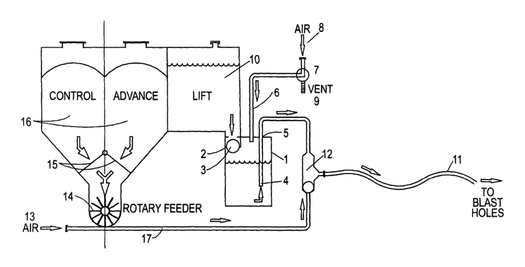
pneumatic loading of solid particulate materials.
Refernng to Figure 1, the explosives delivery apparatus comprises a chamber 1
having an
inlet 2 closable by means of a floating ball valve 3. The inlet 2 is connected
to a source of
emulsion explosives composition comprising an open hopper 10. The chamber 1
has an
outlet 4 in the form of a conduit having a depth within the chamber 1 which if
desired
could be adjusted by displacement through a sleeve 5, for example by sliding
movement.
The chamber 1 also has a chamber pressure control means 6 in the form of
conduit opening
into the chamber and having a valve 7 for selectively connecting chamber 1 to
a further
CA 02413345 2002-12-19
WO 02/29353 PCT/AU01/01252
-9-
conduit ~ leading from a source of compressed air and to a vent 9. The source
of
compressed air (not shown) is preferably regulated.
In an underground mine the source of compressed air is advantageously the main
source of
air to the mine. The chamber 1 has a pV value of less than 10 MPaL.
Accordingly for a
discharge pressure of 200 I~Pa, the volume of chamber 1 must be less than 50
litres. For a
discharge pressure of 600 KPa, the volume must be less than 16.67 litres.
The delivery of emulsion explosives composition from the chamber 1 is
controlled by the
valve 7. Valve 7 is initially adjusted to allow air at atmospheric pressure
within the
chamber 1 to vent to atmosphere via the vent 9 as gravity acting on the ball
of the ball
valve 3 and on the emulsion explosives composition within the hopper 10 forces
the ball
valve 3 to open. This allows the composition to fill the chamber 1. Figure 1
illustrates the
apparatus just after charging of the emulsion explosives composition into the
chamber 1
has started with composition immediately above the level of the outlet conduit
opening 4
in the chamber. As the chamber 1 fills, the ball floats on the composition and
seals the inlet
2 at a predetermined level of the composition. Emulsion explosives composition
in the
chamber 1 is delivered by selectively adjusting the valve 7 to connect the
chamber 1 to the
compressed air conduit ~. The pressure of the compressed air forces the
composition
within the chamber 1 out through the outlet 4 and holds the ball valve 3 in
the inlet in a
closed position as the level of the composition drops. If the level of the
emulsion
explosives composition within the chamber 1 is allowed to fall to immediately
below the
level of the outlet 4, air is able to flow through the outlet conduit which
may serve to clear
the conduit and any associated delivery hose 11 (shown schematically in Figure
1).
However, this may result in undesirable splashing of the composition at
conduit or hose
outlet. The valve 7 may be adjusted to the vent position once the desired
volume of the
emulsion explosives composition in the chamber has been discharged. When the
pressure
drops in the chamber 1, the ball automatically drops under gravity and another
metered
quantity of the emulsion explosives composition is charged into the chamber
from the
hopper. The ball valve is illustrated schematically and in practice will be
guided into the
inlet as it floats on the rising level of emulsion explosives composition.
CA 02413345 2002-12-19
WO 02/29353 PCT/AU01/01252
-10-
The shot volume, that is the volume of emulsion explosives composition in the
chamber 1
above the outlet 4 when the inlet 2 is sealed by the ball valve 3, may be
adjusted by sliding
the conduit 4 up or down in the sleeve 5. This may be performed before or
after the
chamber is filled with the composition.
Figure 2 shows the apparatus of Figure 1 integrated with a solid particulate
feed
mechanism which may be used to selectively deliver the emulsion explosives
composition
from the chamber 1 and/or solid particulate material from one or both of
hoppers 16. The
delivery of emulsion explosives composition and/or solid particulate material
into the
delivery hose 18 is determined by a shuttle valve 12, which is controlled by
the air
pressure.
In order to deliver solid particulate material such as ANFO and/or sensitising
solids from
chambers 16, gates 15 are selectively opened to feed the solid particulate
material into a
charge line 17 by means of a rotary feeder 14. The solid particulate material
fed in charge
line 17 is then delivered to the shuttle valve 12 by the application of
compressed air at 13.
Substantially equal pressure in the outlet conduit 4 and charge line 14
enables both the
emulsion explosives composition and the solid particulate matter to be
delivered
concurrently and to mix in the shuttle valve 8 and/or in the delivery hose 11.
It will be appreciated from the above description that the preferred
embodiment of the
apparatus of the invention may be extremely simple and robust and not require
any
instrumentation for accurate operation. This apparatus may thus be used safely
by semi-
skilled operators and may allow rapid set-up and close down compared to the
available
alternatives. This apparatus may also be relatively silent, which is
particularly important in
underground mines, since it can avoid the use of any pumps. Additionally, with
a pV value
below 10 MPaL, the vessel defining the chamber avoids being classified as a
pressure
vessel thereby reducing maintenance and inspection requirements. This also
reduces the
amount of stored energy in the chamber and provides lower risk to its use.
Those skilled in the art will appreciate that the invention described herein
is susceptible to
variations and modifications other than those specifically described. It is to
be understood
CA 02413345 2002-12-19
WO 02/29353 PCT/AU01/01252
-11-
that the invention includes all such variations and modifications which fall
within its spirit
and scope. The invention also includes all of the steps, features,
compositions and
compounds referred to or indicated in this specification, individually or
collectively, and
any and all combinations of any two or more of said steps, features,
compositions and
compounds.