Note: Descriptions are shown in the official language in which they were submitted.
CA 02413381 2002-11-26
WO 01/93496 PCT/GBO1/02349
1
A Method of Protecting a CrYptosystem from a Multiple Transmission
Attack
The present invention relates to a method of protecting a cryptosystem from a
multiple
transmission attack. It is particularly, although not exclusively, concerned
with public
key cryptosystems.
The present invention, in its various aspects, may preferably be used in
conjunction
with a variation of the encryption and decryption algorithms disclosed in the
NTRU
PCT patent application WO 98108323 ("the NTRU patent application"). However,
it
should be understood that none of the aspects of the invention set out below,
or
defined in the claims, are restricted to use in that specific context.
The invention, in its various aspects, further extends to a computer program
for
. carrying out a method, as described below, a datastream representative of
such a
computer program, and to a physical carrier which carries such a computer
program.
The invention further extends to an apparatus and to a system which is adapted
or
configured for carrying out such a method.
According to one aspect of the present invention there is provided a method of
decrypting a cipher polynomial a using a private key f comprising:
(a) Computing a trial polynomial a, where a = f * a (mod q) and q is
an integer;
(b) Determining, on the basis of the trial polynomial a, whether the
polynomial a has decoded correctly, and if not:
(i) determining which coefficient or coefficients of the trial
polynomial a are likely to have caused the failure to decode;
(ii) adjusting the said coefficient or coefficients to define a new trial
polynomial; and
(iii) attempting to decode the cipher polynomial a using the new trial
CA 02413381 2002-11-26
WO 01/93496 PCT/GBO1/02349
2
polynomial.
This approach, of attempting to identify the individual errors, and correcting
them
where possible, allows a substantial increase in efficiency over prior art
approaches of
attempting to correct the entirety of the trial polynomial a, all at once,
without tracking
individual errors.
To increase efficiency further, the algorithm preferably attempts to
determine, a priori,
which coefficients of the trial polynomial are likely to have caused the
failure to
decode (when that occurs). Preferably, the coefficients are sorted according
to their
respective expectations of being the cause of the failure to decode. The
coefficients
are then taken in order of expectation, largest to smallest, and are adjusted
one by one.
After each adjustment, a further attempt to decode the cipher polynomial is
made
based on the new trial (adjusted) polynomial. If that fails, the next
coefficient is then
tried. This is repeated until the cipher polynomial decodes, or until the
attempt to
decode is abandoned.
In an alternative arrangement, a more complex ordering of polynomials may be
calculated, to allow for the possibility that two or more of the coefficients
may be
incorrect. With this approach, the coefficients in the polynomial are sorted
according
to their respective expectations, singly or in groups, of being the cause of
failure to
decode. The coefficient or group of coefficients with the largest expectation
is then
adjusted to create a new trial polynomial. If that fails, the next coefficient
or groups
of coefficients is taken, and the appropriate adjustments made. The. process
is
repeated until the cipher polynomial properly decodes, or until the attempt to
decode is
abandoned.
The a priori expectation of a coefficient or of a group of coefficients being
the cause of
the failure to decode may be determined according to the respective
coefficient values.
More specifically, the expectation may be determined according to the
proximity of
CA 02413381 2002-11-26
WO 01/93496 PCT/GBO1/02349
3
the respective coefficient values to a predefined coefficient value, or to
predefined
maximum and minimum required values. Where the trial polynomial has been
reduced to the least positive residues modulo q, the predefined coefficient
value may
be taken as q/2. Alternatively, where the trial polynomial has been reduced to
the
least absolute residues modulo q then the expectations may be based upon the
proximity of the coefficients to q/2 and/or to - q/2 + 1. Alternatively, they
could be
based upon proximity to the values q/2 -1 and - q/2.
The proximity of the coefficient values to the predefined value or values may
be used
as the entry points to an error-correction lookup table which defines or
assists in
defining the order of expectation. In a preferred embodiment, the polynomial a
is
centred about zero, and the expectation is based upon the absolute values of
the
coefficients.
A coefficient may be adjusted by adding to it or subtracting from it~an
integral value.
Where applicable, the amount by which the coefficient is to be moved, up or
down,
may be determined in advance according to the parameters that were used to
decode
the original message. Typically, the exact amount of the required shift can be
calculated in advance, along with the direction of the shift.
According to another aspect of the invention there is provided a method of
validating
an encrypted message comprising:
(a) representing the message as a message polynomial;
(b) encrypting the message polynomial to form a cipher polynomial;
~5 (c) hashing together inputs representative of the message polynomial
and the cipher polynomial to create a hash output; and
(d) transmitting to a recipient both an encrypted message defined by
the cipher polynomial and information based on the hash output.
The hash function inputs are preferably concatenated.
CA 02413381 2002-11-26
WO 01/93496 PCT/GBO1/02349
4
Preferably, the hash output is transmitted as plain text to the recipient in
association
with the encrypted message (fox example, concatenated with it); alternatively,
the
hash output may be manipulated in some way before being sent (eg it could
itself be
encrypted, although this would not significantly improve security).
When the message is received, the recipient may confirm validation of the
transmitted
encrypted message by checking the hash output against a re-calculated output
based on
the received cipher polynomial and the decoded message polynomial. If the two
outputs match, the decoded message can be accepted as correct. If they do not
match,
the decoded message should be rejected.
The cipher polynomial may be represented by a series of bits which are packed
to fill
bytes before transmission, anal before input into the hash function. Likewise,
the
cipher polynomial may also be represented by a series of bits (preferably two
bits per
coefficient), and these may be similarly packed into bytes before being
hashed.
The method is not restricted to polynomial-based cryptosystems, and extends
more
generally to a method of validating an encrypted message comprising:
(a) encrypting the messagetext to form a ciphertext;
(b) hashing together inputs representative of the
messagetext and the ciphertext to create a hash output;
and
(c) transmitting to a recipient both an encrypted message defined by the
ciphertext, and information based on the hash output.
By hashing together the messagetext (plaintext message) and the ciphertext,
and
transmitting the hashed value to the recipient, it becomes virtually
impossible for an
attacker undetectably to modify either the messagetext or the ciphertext. If
either is
modified, the corresponding hash created by the recipient will fail to match,
and the
CA 02413381 2002-11-26
WO 01/93496 PCT/GBO1/02349
system then preferably rejects the message. To prevent this information being
passed
back to the attacker, the preferred system does not inform the sender of
whether the
received ciphertext was valid.
5 The plaintext message may, in the preferred embodiment, be a binary
representation of
a sequence of bytes, each byte being representative of an alphanumeric or
other
character in the message that needs to be transmitted securely.
According to a further aspect of the present invention there is provided a
method of
protecting a cryptosystem from a multiple transmission attack, comprising:
(a) applying to a plaintext message to be encrypted a protective
cipher having a cipher key k, to produce a protected message;
(b) creating from the protected message and the cipher key k an
encryption input message; and
(c) encrypting the input message.
This method ensures that the text that is being encrypted will differ in an
unpredictable
way each time, even if an identical message is sent multiple times.
The input message is preferably created by concatenating the protected message
with
the cipher key. The cipher key may be the first part of the input message or
the last
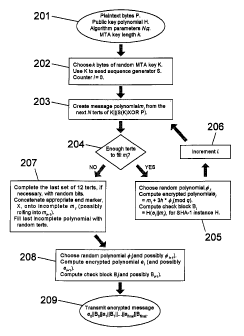
part of the input message. Alternatively, the cipher key may be combined in
any
other convenient way with the protected message to create the encryption input
message. The only requirement is that, when the received message has been
decoded
by the recipient, the recipient should be able to extract the cipher key and
hence
recover the plaintext message from the protected message. Concatenation is
merely
the easiest and most convenient way of sending the cipher key along with the
protected message, and having it easily available by the recipient.
Preferably, the cipher key is recreated, at random, or at least substantially
at random,
CA 02413381 2002-11-26
WO 01/93496 PCT/GBO1/02349
6
for each new plaintext message. The cipher key may be generated by means of a
suitably-seeded pseudo-random number generator or, alternatively, it may be
generated by any "truly random" entropy, such as may be derived for example
from
the timing of keystrokes or mouse movements.
The protected cipher may be a simple stream cipher. In one convenient
approach, the
cipher key is used to seed a pseudo-random number generator which then
generates an
output sequence of pseudo-random numbers. The numbers in that sequence are
then
applied to the individual elements of the plaintext message to produce the
protected
message. That could be done, for example, by adding or subtracting the pseudo-
random numbers to the numbers representing the plaintext message.
In the most preferred embodiment, the plaintext message is represented as a
binary
sequence, with the pseudo-random number generator being arranged to create a
pseudo-random sequence of bits, based upon the cipher key as the seed. The
bits of
the plaintext message are then XORed with the pseudo-random bits to produce
the
protected message. With such an approach, the recipient, once he or she has
decrypted the received message, simply extracts the cipher key k and uses that
to set
the initial state of a.random number generator. That random number generator
may
then be used to generate a sequence of random bits which will be identical
with those
originally used to create the protected message. The plaintext message may
then be
recovered simply by XORing the pseudo-random sequence of bits with the bits of
the
received protected message.
The plaintext message may, in the preferred embodiment, be a binary
representation of
a sequence of bytes, each byte being representative of an alphanumeric or
other
character in the message that needs to be transmitted securely.
The input message is preferably encrypted using a public key cipher, for
example a
polynomial-based cipher. Other ciphers could, however, be used - for example
CA 02413381 2002-11-26
WO 01/93496 PCT/GBO1/02349
7
ciphers based on elliptic curve technology.
According to a further aspect of the present invention a pseudo-random number
generator comprises:
(a) a plurality of first-tier hashing means each capable of receiving
an entropy input and generating a respective hash output; and
(b) a second-tier hashing means, which takes as input the respective
first-tier hash outputs and generates as output a pseudo-random
number.
Preferably, each of the first-tier hashing means may call for additional
entropy input as
and when necessary. Alternatively, additional entropy input may be supplied en
block, to all of the first-tier hashing means at once.
When further pseudo-random numbers are required, one of the first-tier hashing
means
preferably performs a re-hash to create a new hash output. That said new hash
output
is then passed to the second-tier hashing means which uses it in the
generation of the
fiu-ther pseudo-random number. Preferably, the second-tier hashing means
incorporates the new hash output with the hash outputs previously supplied by
the
other first tier hashing means, hashing all of it together to create the
further pseudo-
random number.
Preferably, the said one first-tier hashing means which is carrying out the re-
hash
includes, as part of the re-hash, both its previous hash output and some
further input
from an associated counter means. That ensures that the re-hashed output
differs each
time.
Preferably, the said first-tier hashing means changes whenever a further
pseudo-
random number is to be generated, for example by selecting it in rotation from
the
available plurality of first-tier hashing means. Alternatively, the first-tier
hashing
CA 02413381 2002-11-26
WO 01/93496 PCT/GBO1/02349
means could be selected at random.
A counter means may be provided for each of the first-tier hashing means or,
alternatively, a single counter means may be used to supply counter input to
all of the
first-tier hashing means.
The first and second-tier hashing means may be embodied as software hash
functions,
preferably software hash function objects. Alternatively, the hashing means
may be
embodied in hardware.
The invention extends to a pseudo-random number generator including an entropy
pool for supply entropy to the first-tier hashing means. Where an entropy pool
is
supplied, this may be split up into sub-pools, each of which is arranged to
supply
entropy to a respective first-tier hashing means.
When generating additional pseudo-random numbers, the second-tier hashing
means
may take as input not only the new hash output but also the previous hash
outputs
from the first-tier hashing means other than the said one first tier hashing
means. The
previous hash outputs and the new hash output may be concatenated for use as
input to
the second-tier hashing means.
The invention further extends, more generally, to a mufti-tier system. Tn a
three-tier
system, for example, the pseudo-random output is produced by the third-tier
hashing
means which is fed by a plurality of second-tier hashing means. Each of those
is,
itself, fed by a plurality of first-tier hashing means. The first-tier hashing
means are
provided with entropy input as necessary. Other analogous mufti-tier systems
are of
course possible.
. The invention further extends to a corresponding method of generating pseudo-
random
numbers. It extends, for example, to a method of generating pseudo-random
numbers
which comprises:
CA 02413381 2002-11-26
WO 01/93496 PCT/GBO1/02349
9
(a) supplying an entropy input to a plurality of first-tier hash
functions and generating a respective plurality of hash outputs; and
(b) supplying the hash outputs as inputs to a second-tier hash function
which generates as output a pseudo-random number.
According to a further aspect of the present invention there is provided a
method of
identifying the end of a digital message comprising:
(a) constructing a first string from a plurality of message elements
of a first type, one of the said message elements defining an
end element of the message, followed by zero or more non-message
elements of the first type;
(b) applying a conversion function to the first string to convert it into
a second string comprising a plurality of elements of a second type,
the conversion function being arranged to map all possible strings to an
output space which is smaller than a space defined by all possible second
type element combinations; and
(c) selecting an end of message marlcer to identify the position of the end
element of the message from a plurality of elements of the second type
which, in combination, fall outside the output space of the conversion
function.
The first and/or second strings may but need not be treated on an element by
element
basis, for example as a datastream. Since the strings are, to all intents and
purposes
bi-directional, it will of course be understood that the expression "followed
by" does
not necessarily mean that the non-message elements necessarily have to come
temporarily after the message elements when the first string is transmitted as
a
datastream; they could just as easily temporarily proceed the message
elements.
The conversion function is arranged to map all possible first strings to an
output space
which is smaller than a space defined by all possible second type element
CA 02413381 2002-11-26
WO 01/93496 PCT/GBO1/02349
1~
combinations, thereby defining an "unavailable" space which is inaccessible by
the
conversion function. The end of message marker is selected from a plurality of
elements of the second type which, in combination, fall within that
"inaccessible"
space.
Preferably, the first string comprises a sequence of binary elements, and the
second
string comprises a sequence of ternary elements. In the most preferred
embodiment,
the conversion function is arranged to convert 19 binary elements into 12
ternary
elements. If the message is longer than 19 binary elements (as it usually will
be), it is
first separated into 19-element blocks, each block being treated separately
from the
others. The last block, if not filled by the message, may be padded with non-
message
elements.
The end of message marker may preferably be the same length as the length of
the
I S second string. Specifically, in the preferred embodiment, the end of
message marker
comprises 12 ternary elements.
In more general aspects of the invention, the conversion function may convert
elements in one base to elements in a different base. Preferably, the input to
the
function has a lower base (eg binary) than the output from the function (eg
ternary);
but it may have a higher base.
Once the second string has been created, this may be combined for example by
concatenation with the end of message marker, to form a third string. Where
the
method is used in the context of encryption, the third string may then be
encrypted and
send to the recipient.
The space falling outside the output space of the conversion function may be
divided
up into a plurality of parts, each part being representative of a position
within the first
string, so that the position of the end element of the message may be
identified by
CA 02413381 2002-11-26
WO 01/93496 PCT/GBO1/02349
1~
selecting an end of message marker which falls within the corresponding part.
In the
preferred embodiment, the said space is divided up into 19 parts, each being
representative of one of the positions within the binary first string.
In such an arrangement, the end of message marker may be chosen substantially
at
random from a group of possible markers falling within the said part.
Preferably, within the first string, the end element of the message may lie
immediately
adjacent the non-message elements, if any. That is, however, not essential,
and it
could for example be envisaged that the non-message elements will always be
separated by a fixed number of elements from the non-message elements. This
fixed
number of elements could in certain applications contain header or other
information
that needs to be transmitted each time. All that is required is that the
position of the
end element of the message may uniquely be determined from the end of message
marker.
The invention further extends to a computer program for carrying out any such
method, to a physical caxrier carrying such a computer program, and to a
datastream
representative of such a carrier.
The invention further extends to a method of encrypting a digital message
including
identifying the end of the message using a method as set out above.
Preferably, the
encryption includes the step of encrypting the third string before passing the
encrypted
information to the recipient.
According to another aspect of the invention there is provided a method of
determining the end of a digital message, comprising:
(a) applying an inverse conversion function to a third string
comprising a plurality of elements of a second type;
the inverse conversion function taking as input a plurality
CA 02413381 2002-11-26
WO 01/93496 PCT/GBO1/02349
12
of elements of the second type and converting them to
a plurality of elements of a first type and determining
that a plurality of elements, taken as input to the function,
together comprise an end of message marker when the output
of the function has more significant elements of the first type
than a given value; and
(b) taking, as a first string, the output of the function excluding
that portion of the output which was representative of the
end of message marker, and determining the position within
the first string of an end element of the message according to
the end of message marker.
This, essentially, represents the inverse of the method described above for
identifying
the end of the message. This method will be used by a recipient who needs to
extract
the end of message marker from the information received and, from that,
determine
the position of the last element of the message. With that information, the
full extent
of the message may be determined and the transmitted message extracted.
Preferably, the inverse conversion function takes, as input, 12 ternary
elements and
produces, as output, 19 binary elements. In a more general form of the
invention,
however, the function may simply convert from one base to a different base.
Preferably, the position of the end element of the message may be determined
according to the amount by which the output of the function, when provided
with the
end of message marker as input, exceeds a given value.
The invention further extends to a computer program for carrying out any such
method, to a physical carrier carrying such a computer program, and to a
datastream
representative of such a computer program.
CA 02413381 2002-11-26
WO 01/93496 PCT/GBO1/02349
13
According to another aspect of the present invention there is provided a
method of
decrypting a digital message from an encrypted string comprising:
(a) decrypting the encrypted string to produce a third string;
(b) applying an inverse conversion function to a third string
comprising a plurality of elements of a second type; the
inverse conversion function taking as input a plurality of
elements of the second type and converting them to a plurality
of elements of a first type and determining that a plurality of
elements, taken as input to the function, together comprise an
end of message marker when the output of the function has
more significant elements of the first type than a given value;
(c) taking, as a first string, the output of the function excluding
that portion of the output which was representative of the
end of message marker, and determining the position within
the first string of an end element of the message according to
the end of message marker; and
(d) recovering the message from the first string.
The invention further extends to a cryptosystem incorporating any one or
combination
~ of the methods mentioned above.
According to another aspect of the invention there is provided a method of
carrying
out parallel modulo arithmetic calculations on a device adapted to perform
bitwise
logical operations, comprising:
(a) representing a series of numerical values (x) to be operated
upon, by respective bitwise vectors;
(b) forming a first word (X...o) from one bit of each of the said
vectors, and a second word (X1) from another bit of each
of the said vectors; and
(c) performing bitwise logical operations on one or both of the words.
CA 02413381 2002-11-26
WO 01/93496 PCT/GBO1/02349
14
Preferably, the method described above includes:
(d) representing a series of further numerical values (y), to be
operated upon, by respective bitwise vectors;
(e) forming another first word (Y~o) from said one bit of each of
said vectors, and another second word (Y1) from said another
bit of each of the said vectors; and
(f) performing bitwise operations on both the respective first
words (X..,0, Y~o) or on both the respective second words (X1, Yi).
Preferably, the first word or the respective first words are stored together
in one
location, and the second word or the respective second words are stored
together in
another, spaced, separate location. First storage means and second storage
means
may be provided to achieve that.
In one embodiment, the numerical values and/or the further numerical values to
be
operated upon are on modulo 3 and may, for example, be represented by tents.
The calculations may be carried out in software or may alternatively be
embodied in
hardware, eg by means of XOR, AND, OR, and NOT gates.
The invention extends to a method of encryption andlor decryption which makes
use
of the method listed above.
The preferred method of encryption includes generating a key by adding,
subtracting
or multiplying polynomials having coefficients which are in modulo N (N >_ 3),
using
a method as claimed in Claim 1 or Claim 2, the coefficients of a first
polynomial
comprising the series of numerical values (x) and the coefficients of a second
polynomial comprising the series of further numerical values (y).
CA 02413381 2002-11-26
WO 01/93496 PCT/GBO1/02349
The preferred method of decryption includes adding, subtracting or multiplying
polynomials having coefficients which are in modulo N (N >_ 3), using a method
as
claimed in Claim 1 or Claim 2, the coefficients of a first polynomial
comprising the
5 series of numerical values (x) and the coefficients of a second polynomial
comprising
the series of further numerical values (y).
The invention further extends to a computer program for carrying out the above
method, to a physical carrier carrying such a computer program, and to a
datastream
10 representative of such a computer program.
According to a further aspect of the invention there is provided a digital
device for
carrying out parallel modulo arithmetic calculations by means of bitwise
logical
operations, comprising:
15 (a) means for representing a series of numerical values (x) to be
operated upon, by respective bitwise vectors;
(b) means for forming a first word X..,o) from one bit of each of the
said vectors, and a second word (X1) from another bit of each of
the said vectors; and
(c) means for performing bitwise logical operations on one or both
of the words.
The invention may be carried into practice in a number of ways and one
specific and
preferred embodiment will now be described, by way of example, with reference
to
the accompanying drawings, in which:
Figure 1 illustrates the key creation system in Tumbler;
Figure 2 illustrates the encryption system;
Figure 3 illustrates the decryption system;
CA 02413381 2002-11-26
WO 01/93496 PCT/GBO1/02349
16
Figure 4 illustrates the error correction algorithms;
Figures 5, 6 and 7 illustrate the concept of a wrapping error;
Figure 8 illustrates the order in which coefficients are checked for possible
errors;
Figure 9 illustrates a typical prior art pseudo random number generator
(PRNG);
Figure 10 illustrates the PRNG within Tumbler;
Figure 11 illustrates a circuit diagram for addition modulo 3;
Figure 12 illustrates a circuit diagram for subtraction modulo 3; and
Figure 13 illustrates a circuit diagram fox multiplication modulo 3.
1. Introduction
TumblerTM is the brand name of the present applicant's cryptographic
developers' toolkit. It contains a number of different cryptographic
algorithms
and non-algorithm-specific APIs, but is built primarily but not exclusively
around the NTRU PKCS algorithm as developed by the NTRU Corporation.
Details may be found in Hoffstein, Pipher and Silverman, NTRU: A Ring-
Based Public Key Cryptosystem, J P Buhler (ed), Lecture Notes in Computer
Science 1423, Spring-Verlag, Berlin, 1998, 267-288; and in PCT patent
application W098108323 in the name of NTRU Cryptosystems, Inc. The latter
document will be referred to throughout as "the NTRU patent application".
This algorithm represents a breakthrough in cryptography. Departing from the
traditional world of 'Big Integer' based products, it provides more efficient
and
secure systems based on a polynomial mixing method. Any bare algorithm,
however, is far from usable as a cryptographic product. In between a great
deal
of machinery is necessary. In the case of NTRU its unique style, which is the
source of its superiority, means that much of this machinery must be
reinvented
CA 02413381 2002-11-26
WO 01/93496 PCT/GBO1/02349
17
to cope with the algorithms.
This document describes the unique implementation -of the NTRU PKCS (Public
Key
Cryptosystem) contained within Tumbler. It outlines the problems that one
faces in
attempting to implement the NTRU PKCS as a real world cryptographic tool, and
explains how Tumbler uses innovative techniques in order to solve these
problems.
It should be understood that many of the innovative techniques used within
Tumbler
are independent of each other and could be used singly or in any selected
combination.
For example, although the following techniques are all contained within the
preferred
Tumbler embodiment, they could be used singly or in any combination: error
correction, end of message marker, checking mechanism, large state pseudo
random
number generator, use of modulo arithmetic, and protection from multiple
transmission attacks. It should also be understood that although Tumbler is
primarily
built around the NTRU PKCS algorithm, as set out in the NTRU patent
application,
most of the innovative techniques have a much wider application.
1.1 The Original NTRU PKCS Patent application
The NTRU patent application describes a method for the creation of two
related polynomials, called the public key and the private key. It goes on to
show how the public key can be used to transform a message, in the form of a
polynomial, into an encrypted form. This encrypted message is secure, since
the
task of retrieving the original message, given the knowledge of the encrypted
message and the public key only, is far too complex to be performed by current
technology in a feasible length of time. The encrypted form could also provide
the means of transferring (or storing) the message securely since knowledge of
the private key usually allows recovery of the original message.
CA 02413381 2002-11-26
WO 01/93496 PCT/GBO1/02349
18
1.2 An Incomplete Solution
Using the private key and the encrypted form, the original message can usually
be
recovered. When the message cannot be recovered this is due to errors called
wrapping
or gap failures. It was originally believed that wrapping failures were easily
recoverable with a given method and that gap failures occurred so rarely that
they
were discountable (NTRU patent application ~1.3, p. 31). It became apparent,
however, that the method suggested for fixing wrapping failure often failed to
correct
the error, and that gap failure was common enough to effect usability
significantly.
There was also the issue of error detection. Since the person attempting to
decrypt the
message did not usually possess the original, it was difficult for them to
know whether
the message had decrypted correctly or not.
In computing terms, an arbitrary data file is an arbitrary length string of
binary digits.
The cipher, as described in the original NTRU patent application, encrypts
ternary
. polynomials of a fixed length. It is therefore necessary to provide a method
which
turns a data file into a sequence of fixed length ternary polynomials in such
a way that
the resulting sequence of polynomials can be turned back into the original
data file.
During a cipher's normal use many people, known as attackers, constantly
attempt to
break it. Where NTRU PI~CS is used, the task of retrieving the original
message,
given the knowledge of the encrypted message and the public key only, is far
too
complex to be performed by current technology in a feasible length of time.
The
solution for an attacker is to gain mare information than just the encrypted
message
and the public key.
Depending on the way in which the cipher is used it may indeed be possible for
the
attacker to gain additional information useful for breaking the cipher. The
quick
answer is not to use the cipher in a way that allows this. In some instances,
however,
this can be too limiting for practical purposes. The two addressed below are
situations
CA 02413381 2002-11-26
WO 01/93496 PCT/GBO1/02349
19
where it is desirable to send exactly the same message multiple times, or
where one .
wishes to set up an automated system that might be accessed by a potential
attacker.
The NTRU patent application describes the theoretical algorithm for the
cipher, but
does not address how a real world machine would go about performing this
algorithm.
The theoretical algorithm contains relatively few steps and employs
mathematics that
modern computers are able to perform quickly, and so is naturally fast. The
present
applicants have, however, devised techniques to increase the speed of this
algorithm
dramatically.
1.3 The Tumbler Solution
Tumbler's implementation of the NTRU PKCS bridges the gap between the
theoretical and the practical. It also contains a number of new techniques
that build on
the advances contained in NTRU and can even be used in other areas of
cryptography,
data signal processing and computing.
Below are detailed methods ,of detecting errors and correcting both wrapping
and gap
failure. In order for the cipher to be usable as a practical means of securing
data one
must be able to rely upon the integrity of the decrypted message. Using the
original
methods described in the NTRU patent application, together with the detection
and
correction system outlined below, this is finally believed to be the case.
A coherent 'bit to tent' conversion scheme works in conjunction with an
original 'end
of message marker' system to interface between standard computer data files
and
NTRU PKCS polynomials.
~5
Tumbler contains processes that operate alongside the NTRU PKCS and which
allow
the user to send exactly the same message multiple times, or to use an
automated
system that might be accessed by a potential attacker, without ruining the
cipher's
security.
CA 02413381 2002-11-26
WO 01/93496 PCT/GBO1/02349
As well as analysing a full range of standard mathematical tools in order to
find the
optimum solution for processing the NTRU PKCS, the developers of Tumbler's
NTRU PKCS implementation have created some seemingly anti-intuitive original
5 methods which process much of the NTRU PKCS data at a vastly increased rate.
In order to facilitate commercial cryptography using the NTRU PKCS it is
necessary
to combine this internal algorithm with a great many mechanisms designed to
protect
the cipher's use against common attacks, to interface the cipher with regular
digital
10 data handling, and also to overcome problems inherent in the cipher. The
present
applicant believes that all of this has been achieved in Tumbler.
2. Mathematical Terminolo~y
The NTRU cryptosystem, and the Tumbler version, depends on three integer
15 parameters (N,p,q) and four sets (Lf, Lg, L~, Lm) of polynomials of degree
no greater
than N 1 with integer coefficients. Note that p and q need not be prime, but
it should
be assumed that GCD(p,q) = 1, and that q will always be considerably larger
thanp. In
the Tumbler implementation is normally 3, and q is normally 64, 128 or 256
depending on the size of N. Other implementations could use other values.
One works within the ring of truncated integer polynomials R = Z[X]/(~'-1). An
element F E R will be written as a polynomial or a vector,
N-1
F=~F,..~ =~F,F,..,FN-y.
Addition and subtraction in R works in precisely the same way as in normal
polynomial aritlunetic. Multiplication, however, requires reduction modulo
(Xn'-1).
CA 02413381 2002-11-26
WO 01/93496 PCT/GBO1/02349
21
The symbol * denotes multiplication in R. This stay multiplication is given
explicitly
as a cyclic convolution product,
F* G=H
with
k N-1
H k = ~ FiGk-I + ~ FiGN+k-r = ~ FaGj
i=0 i=k+1 i+ j--=k(mod N )
It should be noted that this is precisely the same as usual polynomial
multiplication
except that the coefficients 'wrap around,' so that the coefficient of ~' is
combined
with (added to) the constant coefficient, the coefficient of .~'~'+I is
combined with the
coefficient ofX, and so on.
In practice, one is usually interested in the value of a polynomial's
coefficients modulo
p or q. In effect many of the operations can be considered to be occurring in
the rings
Zp[~l(X~'-1) or Zq[1i'~/(~'-1), but it is desirable to consider the residue of
a single
polynomial reduced both modulo p and q.
When one performs a multiplication modulo (say) q, the intention is to reduce
the
coefficients modulo q.
There are two useful rules to remember when reducing modulo an integer p:
~ a (mod p) + b (mod p) _ (a + b) (mod p),
~ (c (mod p) ~ a (mod p)) (mod p) _ (c x a) (mod p).
CA 02413381 2002-11-26
WO 01/93496 PCT/GBO1/02349
22
R is not a field. However, the NTRU parameters have been chosen in such a way
that
it is extremely likely for appropriately selected polynomials to have inverses
in R. R is
a unique factorisation domain so, if they exist, these inverses are unique.
Lm consists of all polynomials in R with coefficients modulo p. The elements
of Lf, Lg
and L~ also have coefficients modulo p, but axe of a predefined weight.
Polynomials
in Lg and L~ are defined to have, respectively, precisely dg(l~ and d~(l~
coefficients
with the value 1, dg(l~ and d~(I~ coefficients with the value -1, and the
remaining
coefficients all having the value 0. Polynomials in Lf are defined to have
d~(1~
coefficients with the value 1, and df(l~-1 coefficients with the value -1,
while all the
rest of the coefficients have the value 0. The polynomials in Lfhave one fewer
coefficient with value 1, to allow them to be invertable.
3. Overview
The Tumbler cryptosystem is formed of three separate systems: a key creation
system,
an encrypting system and a decrypting system. This section briefly examines
each of
these three systems and outlines how each is constructed from a number of
underlying
processes.
The NTRU patent application describes encoding and decoding as very simple two
or
three step processes. The Tumbler implementation has introduced many
additional
features, making these processes considerably more complicated. Each of the
three.
processes below is described with the help of a flow diagram. It is
interesting to
compare these three flow diagrams with their equivalents from the NTRU patent
application (figs.3, 4 & 5).
In the case of the key creation system, the process has remained relatively
simple. It is,
however, in the key creation that the greatest advances in efficiency have
been
achieved.
CA 02413381 2002-11-26
WO 01/93496 PCT/GBO1/02349
23
3.1 Key Creation
Here the key creation system is described, as it appears in figure 1 (cf fig 3
of the
NTRU patent application).
101. The key creation system takes in the algorithm parameters N and q. The
parameter p used in the NTRU patent application is fixed to be 3. However,
other
values could be used.
102. The private key polynomial, f, is chosen randomly from the set Lf, which
is
dependent on N, as described in the NTRU patent application (~1.2, p.31).
103. The inverse of f is calculated modulo 3. Instead of using the 'Euclidean
Algorithm,' the more efficient 'Almost Inverse Algorithm' is used. This
algorithm was
found in the paper 'Fast Key Exchange with Elliptic Curve Systems' by Richard
Schoeppel, et al (Advanees in Cryptology - CRYPTO 95, Lecture Notes ire
Computer
Science 973, ed. D. Coppersmith, Springer-herlag, New York, 1995, pp. 43-5~.
It is
possible that the inverse does not exist. In this case, one returns to 102 and
chooses a
new f. In implementing this algorithm a process of fast modulo arithmetic
through
parallel bit operations on a vector representation is used (see ~ 12 for
further details).
104. As for 103, except that the inverse of f is calculated modulo 2. In
implementing
this algorithm a process of fast modulo arithmetic through parallel bit
operations on a
vector representation is used (see ~ 12).
105. Given an inverse modulo a prime, it is possible to calculate from it the
inverse
modulo a power of that prime, using the well-known mathematical technique
colloquially called bootstrapping. This allows us to calculate the inverse
modulo q
(which is always a power of 2) from the inverse modulo 2. Bootstrapping uses
the
CA 02413381 2002-11-26
WO 01/93496 PCT/GBO1/02349
24
following principle. If F is the inverse of f modulo a power of a prime p"=,
then 2F - f
F2 will be the inverse of f modulo p2"'.
106. g is chosen randomly, in a similar way to f, but from the set Gg.
107. This is the same computation as is performed in the NTRU patent
application
(fig. 3, step 350) except that the factorp (= 3) has been included for ease of
use.
108. The private key is the pair f, F3.
109. The public key h may then be published. This has been calculated in step
107.
3.2 Encryption
Here the Tumbler encryption system is described, as it appears in figure 2.
This
should be compared and contrasted with the original encryption system
described in the NTRU patent application (fig. 4). '
In figure 2, the symbol ~~ is used to denote the concatenation of the objects
to
either side.
201. The encryption system takes in the original message data (the plaintext),
P, as a
(binary) string of bytes with an undefined length; the public key polynomial,
h, the
algorithm parameters N and q; and, if necessary, a Multiple Transmission
Attack
protection key length (MTA key), k. The process also makes use of the SHA-1
hashing
function, H(). SHA-1 is defined in the US Government's National Institute of
Standards and Technology's Secure Hash Standards (FIPS 180-1).
CA 02413381 2002-11-26
WO 01/93496 PCT/GBO1/02349
It will be understood, of course, that the plaintext P represents the actual
alphanumeric
(or other) message to be encrypted according to any convenient standard binary
representation.
5 202. If the cipher requires Multiple Transmission Attack protection, this is
applied to
the plaintext before encoding (see ~ 7). For a non-zero k, k bytes of random
data (K)
are generated, and these bytes are used to seed the sequence generator (see ~
11 ). If no
MTA protection is used then k = 0, K = Q~, but the sequence S(K) is logically
considered to be all zeros. In practice a sequence of all zeros has no effect.
This is not
10 the same thing as S(O)!
203. The MTA key, K, forms the first k bytes of plaintext for entry into the
cipher (see
~ 7). This is then followed by the original bytes of plaintext data XORed with
the
output of the sequence generator (see ~ 11). To encode the XORed plaintext it
is
15 necessary to convert the binary data into ternary, in order to fill the
ternary
polynomials (m) that are used by the cipher (see ~ 8). These ternary digits,
or "tents,"
form the message polynomials that are then processed by the PKCS cipher. If
fewer
than N tents remain unprocessed then the remaining tents are placed in the
next
message polynomial and an end of message marker will be created in 207.
204. Provided that enough tents remain unprocessed, a message polynomial is
constructed from the next N and then encrypted. If the plaintext data has been
exhausted and there are insufficient tents to fill the next message
polynomial, an end of
message marker will be created in 207.
205. A random polynomial is chosen and multiplied by the public key. The
product
polynomial is then added to the message polynomial. This process is identical
to that
described in the NTRU patent application (fig 4, step 450) except that the
parameter
p has been incorporated into the public key. The resulting cipher polynomial
is then
packed to fill bytes and inputted into a check hash function, followed by the
message
CA 02413381 2002-11-26
WO 01/93496 PCT/GBO1/02349
26
polynomial using 2 bits per coefficient, which is also packed to fill bytes.
The check
hash is computed and concatenated to the end of the cipher polynomial (see ~
6). The
output from this hash forms check block BT.
206. Having encrypted a message polynomial one then proceeds to the next
polynomial using the next N tens of plaintext.
207. It is unlikely that the plaintext data will fill an exact number of
message
polynomials or even an exact multiple of 19 bits for conversion into terts.
When all the
polynomials that can be filled completely using the process described in 203,
204, 205
& 206 have been processed, the last message polynomial is completed using the
end of
message mechanism (see ~ 9). This mechanism creates a 12 tent end of message
marker. This marker is included in the plaintext and may not fit in the last
incomplete
message polynomial. In this case the end of message marker will spill over
into
another message polynomial. The last polynomial is completed with random terts
if
necessary.
208. The last message polynomial (or possibly the last two message
polynomials)
containing the last incomplete plaintext message polynomial and the end of
message
marlcer are now encrypted in the same manner as all other message polynomials.
209. The concatenation of each encrypted polynomial packed to fill bytes, but
with the
last incomplete byte (if it exists) completed with zeros, followed immediately
by its
associated check block, forms the encrypted message (ciphertext).
3.3 Decryption
Here the Tumbler decryption system is described, as it appears in figure 3. It
should be
compared and contrasted with the original decryption system described in the
NTRU
patent application (fig. 5).
CA 02413381 2002-11-26
WO 01/93496 PCT/GBO1/02349
27
301. The decryption system takes in the algorithm parameters N and q, the
ciphertext,
E, the private key polynomials, f and F3, the error correction level, and, if
necessary,
the MTA key, k. The process also makes use of the SHA-1 hashing function, H().
In
figure 3 the symbol ~~ is used to denote the concatenation of the objects to
either side.
302. i is a counter used to refer, in order, to specific encrypted
polynomials. R will
contain the decrypted plaintext data with the MTA protection still applied
(see ~ 7).
303. Each encrypted polynomial and its related check block are reconstructed
from the
ciphertext by simply reversing the packing sequence used in 209.
304. The message is multiplied by the private key, and then by the private key
inverse.
This is identical to the process described in the NTRU patent application
(fig. 5,
steps 570 and 580), except that the result of the first multiplication is
recorded in case
it is needed for error correction.
305. A hash is made of e; and b;, in the same way as that of e; and ml in 205
(see ~ 6),
treating the decrypted polynomial b; as the message polynomial m;. This hash
is
compared with the transmitted check block B;. In the event that error
correction needs
to be employed on a polynomial, many such hashes may need to be calculated
using
the same e;. It may therefore be efficient to record the state of the hash
function after
the input of e;, but before the input of b;.
306. If the transmitted check block matches the hash created in 305 then the
decoded
polynomial, b;, is accepted as the original ith message polynomial. The terts
of these
message polynomials need to be converted back into bits (see ~ 8). This
conversion is
performed in sets of 12 terts.
CA 02413381 2002-11-26
WO 01/93496 PCT/GBO1/02349
28
307. The bit to tent conversion converts sets of 19 bits into a subset of the
possible sets
of 12 tents. When a set of 12 tents is a member of this subset it is passed
for conversion
back into bits; otherwise it is not a converted set of 19 bits but an end of
message
marker (see ~ 9).
308. The tents axe converted into bits (see ~ 8) and the result is
concatenated to R. R
is of course a binary string (representing a sequence of bytes).
309. Having decoded the previous polynomial the decryption system then
proceeds to
the next encrypted polynomial.
310. If the transmitted check block does not match the hash created in 305
then the
decoded polynomial, b;, is not the original itl' message polynomial.
311. If the optional error correction is active the error correction system
attempts to
recover the original message polynomial (see ~ 5).
312. The error correction system will report back its success. If it is
successful then the
resulting b; (a different b; from that calculated in 304) is accepted as the
next message
polynomial, and the cipher continues as normal.
313. This point is reached if an error has occurred and has not been
corrected. The
original plaintext cannot therefore be recovered. In most cases the whole
message is
discarded at this stage. This is because most uses of a PKCS require the whole
intact
message. It is possible, however, simply to record which bytes of the
resulting
plaintext relate to the current incorrect message polynomial, skip to stage
306, and
continue as normal. Only those plaintext bits directly converted from the
inaccurate
message polynomial will be affected.
CA 02413381 2002-11-26
WO 01/93496 PCT/GBO1/02349
29
314. An out of range set of 12 terts indicates an end of message marker. All
previous
blocks of tens are converted to bits and concatenated to R. Finally this block
is
interpreted using the end of message mechanism (see ~ 9). This may require the
removal of some of the bits contained in R. Terts that have not yet been
converted are
discarded.
315. At this stage R is the plaintext data with the MTA protection still
applied. The
l
first k bytes form the MTA key K. These are used to seed a sequence generator
S(K).
If no MTA protection is used then k = 0, K = QJ, but the sequence S(K) is
logically
considered to be all zeros. In practice a sequence of all zeros has no effect.
This is not
the same thing as S(Q~)! The output from S(K) is XORed with R to produce P
(see ~
7).
316. The recovered plaintext data is the binary string P, representing the
bytes of the
actual message.
4. Decoding Failure
Each time a cipher polynomial is decoded using the NTRU algorithm there is a
small
probability that it will fail to decode back to the original message
polynomial.
To decrypt the cipher polynomial a using the private key f, one first computes
a = f * a (mod q ),
choosing the coefficients of a in the interval from -q/2+1 to q/2. Treating a
as a
polynomial with integer coefficients, the message polynomial can usually be
recovered by computing
CA 02413381 2002-11-26
WO 01/93496 PCT/GBO1/02349
F~, * a (mod p ),
where Fp is the inverse of f modulo p ( Fp * f = 1 (mod p)).
The polynomial a satisfies
a---- f *e---- f *~*h+ f *m(mod q)
= f*p~*Fy*g+ f*m(mod q)
= paddi f *m(mod q)
5
Consider this last polynomial p~ * g + f * m. For appropriate parameter
choices, it is
possible to ensure that in almost every case all its. coefficients lie between
-q/2+1 and
q/2, so that it does not change when its coefficients are reduced modulo q.
This means
that reducing the coefficients of f * e~ modulo q into the interval from -
q/2+1 to q/2,
10 recovers exactly the polynomial
a= paddi f *m.
'Appropriate parameter choices' refers primarily to the values dg(1~, d~(l~
and df(l~,
defined in ~ 2. The lower these values are, the greater the proportion of
coefficients in
the polynomials g, ~ and f are zero. As a consequence of this, the probability
that a
15 coefficient in the above polynomial will be close to zero becomes greater.
However,
these values also dictate how many possible polynomials there are of each
type, and
therefore how effective the cipher's security is. If these values are laxge
enough, there
will be too many possible values of g, ~ and f for an attacker to be able to
guess their
exact value in a feasible amount of time. If +.hese values are so small that
there is no
20 chance that any of the coefficients in the above polynomial will lie
outside the range
-q/~+1 to q/2, then the security of the cipher will be compromised.
CA 02413381 2002-11-26
WO 01/93496 PCT/GBO1/02349
31
The parameter choices used in Tumbler give a probability of approximately 1 in
10000
that the polynomial
p~*g+f*~rz
will have a coefficient that lies outside the range -q/2+1 to q/2. This means
that the
value of some coefficients) will be translated by ~q during the first step in
decoding
and will therefore have an altered value modulo 3.
Example
Figures 5, 6 and 7 give a visual example of a wrapping error.
Figure 5 graphs an example polynomial f * a that has been reduced to the least
positive residues rnodulo q. Fifty coefficients are represented by dots placed
at
heights relative to their value (between 0 and q). This is the polynomial that
the
decoder will recover halfway through the decoding process. The polynomial is
displayed using the least positive residue classes, as the simplest reduction
modulo
a power of 2 in a computer will leave numbers in these classes. In order to
recover
the message the polynomial must be shifted into the least absolute residue
classes
(between -q/2 + 1 and q/2). However the current form of the polynomial has the
advantage that all the coefficients that are most likely to wrap incorrectly
are
collected together in the centre of the polynomial. This zone is highlighted
on the
graph (the area marked as 501).
Figure 6 shows the same polynomial as in figure 5 except that it has now been
shifted into the least absolute residue classes modulo q. The area that was
marked
as 501 in figure 5 has now been split into two and is marked as 601 and 602.
The
coefficient that was marked as 502 in figure 5 was just above the q/2 line and
has
therefore been shifted down by q and now sits at the bottom of the graph
(maxked
CA 02413381 2002-11-26
WO 01/93496 PCT/GBO1/02349
32 .
as 603). This is the form of the polynomial that will be convoluted with F3 in
order
to recover the original message polynomial.
Figure 7 graphs the polynomial p~ * g + f * m, relating to the polynomials
graphed
in 5 and 6. This polynomial is not reduced modulo q, but it is hoped that its
coefficients will all lie in within the range -q/2+1 to q/2 so that the
polynomial
from figure 6 will be an exact match. If so, then the message will be
recovered
without error. This will happen, with appropriate, parameter choices, in all
but a
very small fraction of cases. In this example the coefficient marked as 703
lies
outside the stated range. This means that the polynomial f * a that was shown
in
figure 6, while equivalent to this polynomial modulo q, is not the same and
not
equivalent modulo 3. The coefficient 701 has been wrapped to the position
marked
603 in figure 6.
It is important that there exists some means by which it is possible to know
whether or
not an error has occurred. The polynomial ~ is known only to the encrypter,
while the
polynomials g and f are known only to the decoder, so it is impossible to
predict
whether a wrapping failure will occur. Detecting failure involves the use of
some sort
of a check hash that confirms the integrity of the original data during the
encryption/decryption process. Such a check is also necessary to prevent some
forms
of attack.
The mechanism employed by Tumbler to detect decoding failure is detailed in ~
6, and
the means of correcting these errors follows in ~ 5.
r
5. Error correction
Wrapping errors were a recognised problem at the time that the NTRU cipher was
proposed ( NTRU patent application, ~1.3, p. 31). However, the routine
suggested for
resolving this was flawed, and did not correct many instances of wrapping
failure. The
CA 02413381 2002-11-26
WO 01/93496 PCT/GBO1/02349
33
method involved shifting the polynomial a from above, by a multiple of 3. This
changed the value of the coefficient that was being incorrectly wrapped so
that it was
not wrapped, and did not alter the value of any of the coefficients when they
were
reduced modulo 3. Unfortunately, this often caused a coefficient, whose value
lay at
the other end of the range, to be wrapped incorrectly, where previously this
would not
have occurred.
The wrapping error correction that was suggested also failed to correct an
error known
as gap failure. This occurs when an incorrectly wrapped coefficient has a
value that is
at least as close to zero as a correctly wrapped coefficient of the same sign.
This was
not originally considered an issue, as these failures were thought to be
extremely rare.
A gap failure can actually occur once in every ten million polynomials, which
is
sufficiently often to be noticed by many applications.
The principle behind Tumbler's error correction system is simple. If there is
an error
then fmd it and correct it.
The difficulty is that there are N coefficients which, viewed naively, could
be wrong in
two possible ways (when treated as modulo 3 values). There could also be
multiple
simultaneous errors. Checking every possible error is therefore equivalent to
trying out
every possible ternary polynomial until one works. Due to the nature of the
cipher this
would take an unfeasible amount of time. Furthermore, the error may not even
have
been caused by decoding failure, but by an error in transmission or a
deliberate
alteration by an attacker.
The Tumbler solution is based on the fact that not all possible errors are
born equal. If
one orders the possible causes of error from most likely to least likely then
an
extremely efficient search can be performed for the cause of the error. In
practice the
most common cause of a decoding failure will be the cause approximately 9999
errors
in 10000 (for the parameter choices currently used in Tumbler).
CA 02413381 2002-11-26
WO 01/93496 PCT/GBO1/02349
34
Recalling the cause of decoding failure in ~ 4, the algorithm parameters have
been
chosen so that a certain polynomial's coefficients are almost always inside
the range
-q/2+1 to q/2. When they are not within the range a decoding failure is said
to have
occurred. The chance of a coefficient falling outside this range is, in
practice, about 1
in 10000 per polynomial. The chance of two coefficients falling outside this
range
simultaneously is less than 1 in 100000000 per polynomial, and so on for more
simultaneous errors. Also, when a coefficient falls outside this range it will
almost
always fall outside by only a small amount. The greater the distance, the less
likely it
is that a coefficient will fall at that distance outside the range.
Furthermore, when a coefficient falls just above this range it will be wrapped
to the
bottom of the range. When a coefficient falls just below this range it will be
wrapped
to the top. In the first case its value will be q too small, which means that
it will be x
too small modulo 3 where x is the smallest positive residue of q modulo 3. In
the latter
case it will be x too large.
This provides a simple means of finding the error. The values that lie closest
to the top
and bottom of the range -q/2+1 to q/2 are checked, and attempts are made to
correct
their values modulo 3 by adding or subtracting x (depending on whether the
values are
at the bottom or top of the range respectively).
Figure 8 shows the same graph as that in figure 5 (explained in ~ 4). The area
surrounding the line q/2 is highlighted and marked as 801. The coefficients
that lie
within this area are the ones that are most likely to cause an error. In order
of their
proximity to the line q/2 the first 5 coefficients are labelled 802, 803, 804,
805 and
806. The most likely cause of an error would be the coefficient marked 802
having a
value that is x too small. This is exactly the error that was described in the
example in
~ 4, and adding x to this coefficient's value would indeed correct the error.
CA 02413381 2002-11-26
WO 01/93496 PCT/GBO1/02349
The exact method that one should employ to correct these errors depends
heavily on
the use to which the cipher is being put, and the platform upon which it is
being
implemented. An example algorithm is given below. The premise of this method
is
that efficiency can be achieved by making multiple correction attempts as fast
as
5 possible. However, 9999 out of 10000 errors will be corrected on the first
attempt. It is
probably best, in terms of speed, to check in the shortest possible time for
the most
likely error and only do the work necessary for continuing the search if that
first
attempt fails.
10 Since the errors are only occurring in the order of once in every 10000
polynomials
the speed diffef ence will be snnall on average and will only be important
when
constant flow speed is an issue. The method described here does have some
advantages. Given appropriate G tables (see below), it will fix all decoding
errors in a
reasonable time. After the first few steps the original data can be stored in
a very
15 efficient format, and the original modulo q data need never be referred to
again.
Figure 4 is a flowchart of the following error correction algorithm. No
equivalent
algorithm was presented in the NTRU patent application. This flowchart is
designed as
a counterpart to the flowchart describing the decoding system (see figure 3).
401. The error correction routine uses the algorithm parameters N and q. It
also uses
the private key inverse, F3, but not the private key itself.
The correction level determines how fax the error correction routine should
continue.
The error correction must be non-zero, or the error correction routine would
never
have been called in the first place. Almost all errors are fixed very rapidly.
The
correction level allows one to control how certain one can be that an error is
due to a
cause other than decode failure. An arbitrarily high correction level, when
the cause of
the error is in transmission, would cause the process to continue for an
arbitrarily long
3 0 time. Any existing errors axe extremely likely to be corrected in the
first few attempts.
CA 02413381 2002-11-26
WO 01/93496 PCT/GBO1/02349
36
It is therefore possible to conclude very quickly that the chance of a yet
undetected
error is negligible and that the failure of the polynomial to decode is more
likely to be
caused by a problem that occurred during the transmission of the message.
The correction routine takes in the half decoded mod q polynomial a;, and the
cipher
polynomial e;. These relate to the polynomials used by the decoding system
(see figure
3). e; is only used for creating the check block. It is possible to avoid
repeatedly
inputting e; into the hash instance by recording the state of the hash
function after
inputting e1 and then returning to this state, instead of a new hash instance,
when a new
check is required.
The table G~k is constructed from experimentation and allows one to control
the order
in which varying numbers of concurrent errors are corrected at various depths.
Since
almost all errors are corrected immediately it is hard to determine ideal
values for this
table beyond the first couple of entries. Ipso facto the exact values are of
little
importance.
402. The corrected level is simply a counter used to compare with the
correction level.
The value j is used in conjunction with the table G. It tells us which row of
G is
currently being used.
The value of x tells one how much a value, incorrectly wrapped modulo q, has
been
altered modulo 3. More generally, if the value ofp from the NTRU patent
application
is chosen to be something other than 3, then x will be calculated as
x = q rem p.
Centring a polynomial modulo q refers to shifting it into the least absolute
residue
classes (centred around zero). It should be noted that it is not necessary to
use the
range -q/2+1 to q/2. Instead one could use the range -ql2 to q/2-1.
CA 02413381 2002-11-26
WO 01/93496 PCT/GBO1/02349
37
403. At this point a list is created which will order the coefficients of a;
by the
proximity of their values to -ql2 and q/2. If values exactly equal to q/2 were
wrapped
down in step 402, then negative valued coefficients should be listed before
positive
valued coefficients with the same absolute value, and vice versa if values
exactly equal
to -q/2 were wrapped up. In the example described in figure 8, the list would
begin
with the coefficients labelled 802, 803, 804, 805 and 806 in that order. It is
possible to
record only the distance of each coefficient's value from the edge of the
range and not
the value itself. The whole value is used here as it makes it easier to follow
the
process.
404. After being reduced modulo 3, the original modulo q polynomial a1 is no
longer
used.
405. k is initialised. This will control the number of simultaneous errors for
which a
check is made. To begin with a check is made for one incorrectly wrapped
coefficient.
406. Here one takes the current depth at which checks should be made from the
table.
If one is on the first row of the table the checking procedure should start at
depth 0. It
should be noted that if a value is no larger than the one for the previous j
then there are
no unchecked k-tuples in 407, and the algorithm will skip straight ~to the
next value of
k.
407. The algorithm searches through all the k-tuples of coefficients with
values that
axe no more than a certain distance away from ~q/2. At this point it is
determined
whether there are any k tuples left that have not yet been checked. A k tuple
that has
been checked during a search at a smaller depth need not be rechecked.
408. A k tuple of coefficients, whose values all lie within the given range,
is chosen.
This k tuple should be distinct from any k tuple that has been chosen at a
previous
CA 02413381 2002-11-26
WO 01/93496 PCT/GBO1/02349
38
iteration of the algorithm. The values of the chosen k tuple are then altered
to
compensate modulo 3 for a possible mis-wrapping modulo q.
409. Using the altered a;; the decoding process is completed.
410. A check is made to see whether the decoded polynomial and the cipher
polynomial pass the integrity check.
411. If the integrity test passed then b; is accepted as the next decrypted
polynomial.
412. The possible k tuples having been exhausted, the search is now extended
to a
greater possible distance from ~q/2.
413. The value of the table G at (j, k) gives the depth at which one should
stop
searching for an error in a k-tuple for the current value of k.
414. The counter that records how far has been searched, in relation to the
intended
extent of the search, is incremented. There are obviously more economical
means of '
achieving this than having a dedicated counter.
415. At this point a check is made to see if the corrected level has yet
reached the
supplied correction level.
416. If checking has been performed as far as the correction level specified
without
~ having stopped at stage 411 with the decoded polynomial, then the search is
abandoned and the polynomial remains uncorrected. Realistically, with a
minimum
correction level this will still only occur when the error is caused by
something other
than decoding failure.
CA 02413381 2002-11-26
WO 01/93496 PCT/GBO1/02349
39
417. One increases the number of simultaneous errors for which the correction
procedure is to be performed.
418. The rows of G are zero terminated. When an end is reached, k is reset,
and the
search is begun for a singleton error again.
419. The algorithm moves to the next row of G.
f
The following example shows in more detail how the table G is used.
Example
a; = 45 - 117x - 127x2 - 45x3 -117x4.
q/2 = 128
index value sign
0 45 +
1 117 -
2 127 -
3 45 -
4 117 -
Index 2 corresponds to the coefficient with the greatest absolute value. The
coefficients with indices l and 3 have the same absolute value and the same
sign, so it is completely arbitrary which of these two is listed first. For
the rest
of the example 1 will be listed first. Indices 0 and 4 have the same absolute
value and different signs, so, assuming that one uses the range -127 to 128, 3
is
listed first.
CA 02413381 2002-11-26
WO 01/93496 PCT/GBO1/02349
The resulting ordering will therefore be ~(2;-127), (I,-lI7), (4,-117), (3,-
45),
(0,45)x.
q = 128 = 3 * 42 + 2. Therefore x = 2.
5
Consider the simplified table G~k =
k=1 k=2 k=3 k=4
10 j= 1 3 2 0 0 -
j =2 11 11 4 0
j =3 11 11 5 0
15 -
j =4 15 12 11 1
This table indicates the best order in which to check for errors. If at any
stage
the error is discovered and corrected, then the checking procedure will be
20 stopped.
The procedure starts with an attempt to correct the singleton errors that are
equal to -128 or 128. There are none, so it proceeds to singletons in the
ranges
-128 to -127 or 127 to 128. These ranges contain one such, as pointed to by
the
25 first index in the sample ordering, i.e. 2. Since this coefficient is
negative the
algorithm attempts to correct it by adding 2. For the purposes of this example
it
shall be assumed that this fails.
CA 02413381 2002-11-26
WO 01/93496 PCT/GBO1/02349
~1
Since G(1,1) = 3, one should continue trying to correct singletons until one
has
tried all singletons in the ranges -128 to -126 or 126 to 128. There are no
more
singletons in that range.
At this 'point it is better to try to correct a pair. However there are no
pairs in
the largest range specified by G(1,2) = 4. G(1,3) 0, and therefore one must
now
switch to the next row of G and start searching for a singleton error once
more.
The seaxch starts where it left off in the previous row, with a depth of 3,
and
looks for singletons down the list up to a depth of 10. At 10 two more
potential
errors are found. Once more it shall be assumed that correcting these errors
fails.
Now another attempt is made to correct for a pair of errors, starting where
the
search left off, at a depth of 4. When a depth of 10 is reached three
coefficients
are found in that range, and therefore 3 potential pairs. Because index 2 is
first
in the list these pairs would be corrected in the following order: (2,1),
(2,4) and
finally (1,4).
For this example it shall be assumed that one of these pairs was indeed the
cause of the
error. However, it is important to remember that in practice an error will
almost
always be corrected in the first few attempts.
6. Text Awareness
If a cryptosystem is able~to determine whether the encrypted data is a valid
encoding
of its associated plaintext, it is then said to be plaintext aware. This is
usually achieved
with some sort of check hash.
CA 02413381 2002-11-26
WO 01/93496 PCT/GBO1/02349
Depending on their use, systems that are not plaintext aware may be
susceptible to
attack. An attack that takes advantage of a system's lack of awareness works
in the
following way:
An attacker intercepts an encoded message. The attacker then modifies the
encoded
message slightly before sending it on to the original intended recipient.
This slight modification may sometimes turn the message into an invalid
ciphertext,
i.e. one that could not be an encoded form of any plaintext. In such cases the
decoder
is unable to decrypt the message, and will generally inform the sender (who is
the
attacker in this scenario) that the message failed to decode.
Alternatively, the modified message might be a valid ciphertext. In such a
case the
decoder will decode the message and attempt to interpret it. Since it has been
modified
whilst encoded, the decoder may not be able to make any sense of the message,
but
this is irrelevant to the attack.
The attacker repeats this process several times, recording at each stage which
modifications yield valid ciphertexts. By analysing this, the attacker is able
to
determine some of the original message.
Tumbler takes this approach further and automatically creates a regular hash
check
based on both the plaintext and on the ciphertext. This allows us to describe
Tumbler,
generally, as 'text aware' .
Tumbler preferably uses the SHA-1 (Secure Hash Algorithm 1) to compute a check
hash for each encoded polynomial. SHA-1 is defined in the US Government's
National Institute of StandaYds ahd Technology's Secu~ a Hash Standard (FIPS
180-1).
CA 02413381 2002-11-26
WO 01/93496 PCT/GBO1/02349
43
As each message polynomial is encoded, both the original message polynomial
and
the resultant cipher polynomial are used as input into an instance of the SHA-
1
algorithm.
During encoding, the cipher polynomial is taken as input first, as this speeds
up the
decoding process in the event of a decoding error. The cipher polynomial is
first
packed to fill bytes as described below, for transmission. The bits required
to represent
the first coefficient are placed in the least significant end of the first
byte, and so on,
and the last byte finished with onset bits if necessary.
The message polynomial is then packed to fill bytes, each coefficient this
time being
represented by two bits. Both bits are onset if the corresponding coefficient
is zero;
the first bit is set and the second is onset if the corresponding coefficient
is -1; anal
both bits are set if the corresponding coefficient is 1. It is never the case
that the
second bit is set while the first is onset.
The packed cipher and message polynomials are concatenated, and are then
hashed
together using the SHA-1 algorithm. The hashed output is then transmitted to
the
recipient (unencrypted) along with the ciphertext. Typically, the addition of
the hash
will add around 20 bytes to the amount of text to be transmitted. Fewer
additional
bytes could be used, but this would result in lower security.
Example
The message polynomial {-1,0,1,1} would be encoded as the byte 10001111.
The last byte is finished with onset bits if necessary. In this encoded form
the
polynomial is concatenated to the end of the packed ciphertext, and hashed for
transmission to the recipient.
CA 02413381 2002-11-26
WO 01/93496 PCT/GBO1/02349
44
During decoding, the ciphertext and the decoded message polynomial are
concatenated and are inputted into the SHA-1. The output from the SHA-1 is
then
compared with the original hash computed during the encode process, and
received
along with the ciphertext.
If an attacker modifies an encoded message therefore, even if the modified
data can be
decoded, it is still computationally infeasible for the hash of the decoded
message to
match the hash of the original message. This makes it essentially impossible
to alter
the ciphertext and still pass this test.
The system then rejects all messages whose hash fails to match the original,
whilst
being careful not to inform the sender of whether the ciphertext was valid.
It is possible that wrapping failure may have caused the fault in the decoded
message
polynomial. If error correction is switched on, the cipher will attempt to
correct the
fault by using the algorithm described above. At each stage it will be
necessary to re-
compute the check hash to see whether the error has been rectified. Since the
ciphertext remains the same and only the retrieved message polynomial differs
for
each check; it is possible to input the ciphertext into the hash only once and
input the
message polynomial each time.
The general method of hashing the ciphertext and the plaintext together to
produce an
integrity test for both is not NTRU dependent, but works equally well for
other
ciphers.
7. Multiple Transmissions
Tumbler includes the option of adding protection against Multiple Transmission
Attacks (MTAs).
CA 02413381 2002-11-26
WO 01/93496 PCT/GBO1/02349
Should the same message be encrypted and transmitted more than once using the
same
public key and without MTA protection, it may then become susceptible to
attack.
It is important to be aware of the possibility of predictable similarity
between two
5 messages. Most obviously identifiable are message headers, such as those
used in
email, which are often. predictable. If the first few bytes of several
messages are
identical then their first message polynomials will also be identical and
hence
susceptible to a MTA.
10 Suppose that a list of prices is transmitted on a regular basis. If the
attacker makes the
correct assumption 'that the prices have not changed, this would also allow
them to
employ a MTA.
The security of a single message polynomial is dependent on the random factor
used in
15 the encryption of that polynomial. If an attacker is able to determine the
random factor
and has access to the public key, it is then trivial for them to retrieve the
original
message.
Each time a message is sent, the random factor is determined 'on the fly' for
each
20 polynomial. This means that if exactly the same message is sent more than
once it will
contain a different random factor. If ~an attacker knows for certain that two
or more
intercepted messages have exactly the same plaintext, they can compare these
messages in an effort to determine the random factors used.
25 Even without MTA protection it is not generally possible to determine the
entirety of
the random factors from just two copies. However, even sending two copies
might
significantly compromise the security of the message, while sending multiple
copies
can allow the attacker to determine most (and eventually all) of the message.
CA 02413381 2002-11-26
WO 01/93496 PCT/GBO1/02349
46
The Tumbler MTA protection system employs a simple stream cipher together with
a
randomly selected key (eg using a pseudo-random number generator) to ensure
that
the plaintext message differs randomly from any other identical message sent
with the
same key. The stream cipher does not directly add to the security of the
message as it
is broadcast with its key, and thus need not be a particularly secure cipher.
It must only
ensure that two identical plaintexts will differ from one another in an
unpredictable
manner.
Encoding with the Tumbler 1VITA protection option adds a random (or pseudo-
random) MTA key to the start of the plaintext. This key is then used to set
the initial
state of the Tumbler Sequence Generator (see ~ 11, and step 202 in figure 2).
Subsequent bytes of plaintext data are then XORed with output from the
Sequence
Generator before being inputted into the PI~CS cipher: see step 203 of figure
2.
During decoding, (figure 3), the first k bytes of data returned from the PI~CS
cipher
are used to set the initial state of the Sequence Generator (see ~ 11).
Subsequent bytes
are XORed with output from the Sequence Generator before being outputted as
the
decoded plaintext: see step 315 of figure 3.
8. Bits to Terts
Whereas data is conventionally stored as bits, the preferred PI~CS algorithm
handles
messages as polynomials whose coefficients can take the values 0, 1 or -1. The
message polynomial is just a string of ternary digits (tens). A method is
required for
convening the bits into tens and back again.
Each complete set of 19 bits of the message is converted in the present
invention to 12
tens. This gives a packing efficiency of 98.65%, while allowing the arithmetic
operations used in conversion to be performed using 32 bit integers. A method
using
CA 02413381 2002-11-26
WO 01/93496 PCT/GBO1/02349
47
integers of more than 64 bits would be more efficient, but would offer a gain
in
packing efficiency that would be negligible when compared with other packing
issues.
8.1 Conversion of bits to tarts
x should be taken to be the integer whose least significant 19 bits are set in
the same
configuration as the block of 19 bits from the message, and whose other bits
are all set
to zero. Here tarts should be assumed to be integers taking the value 0,1 or -
1.
1. x is divided by 3 and the remainder calculated. This value can then be used
to
determine the next tart. 0 determines that the value of the tart is 0, 1
determines
that the value of the tart is 1 and 2 determines that the value of the tart is
-1.
2. x is divided by 3, discarding any remainder.
3. Perform steps 1 and 2 a total of twelve times.
Clearly, this process could be accelerated if in step 1 x was divided by 81
instead of 3,
and the remainder then used with a table of the 81 possible 4-tuples (ordered
sets with
four elements) of tarts to determine the values of the next four tarts. x
would then be
divided by 81 in step 2. If this approach were used, the process would only
require
three iterations instead of 12.
Even greater speed could be achieved by a method that divided x by 729, taking
the
remainder, before using a table of 729 possible 6-tuples of tarts to determine
the
values of the next six tents, and then dividing x by 729. This option would
require only
one remainder and one division operation. However, each method offering such
an
improvement in speed would also suffer from a corresponding increase in code
size.
The ultimate method in terms of speed would use a straight lookup on a table
of all
531441 possible 12-tuples.
CA 02413381 2002-11-26
WO 01/93496 PCT/GBO1/02349
48
Whichever of the above methods is used, the conversion process gives values in
the
range {0,0,0,0,0,0,0,0,0,0,0,0) to {-1,0,0,-1,1,0,-1,-1,1,-1,-l,-1~. Thus, not
all possible
12-tuples of tents can be generated. This is because 312 = 531441 is greater
than 219 =
524288. This is important as sets of tents that lie outside this range are
used to signify
the end of the message.
The last incomplete set of 19 bits, if any, is padded out to 19 bits with the
required
number of random bits. The length of the real message data, excluding the
padding, is
remembered and used for determining the value of the end of message marker.
See ~ 9
for further details on this.
Example
For the purposes of this example, it should be assumed that the sequence of 19
bits is 0101101101001100010, ordered from the first and least significant bit
to
the last and most significant bit. Regarded as a decimal integer, this
sequence
of bits is 144090. The value of each tent can be calculated as follows:
Number Remainder when New value of x after division by Value of
of x is divided 3 (discarding remainder)tent
tent by 3
0 0 144090 = 3 = 48030 0
1 0 48030 = 3 = 16010 0
2 2 16010 = 3 = 5336 -1
3 2 5336 = 3 = 1778 -1
4 2 1778 = 3 = 592 -1
5 1 592 = 3 = 197 1
6 2 197=3=65 -1
CA 02413381 2002-11-26
WO 01/93496 PCT/GBO1/02349
49
7 2 65-3=21 -1
8 0 21-3=7 0
9 1 7-3=2 1
2 2-3=0 -1
11 0 0-3=0 0
Therefore the bit sequence 0101101101001100010 will be converted into the
tent sequence f 0,0,-1,-1,-1,1,-1,-1,0,1,-1,0}.
5 8.2 Conversion~of tents to bits
When the data has been decoded it will again take the form of a ternary
polynomial,
and the'bit to tent conversion process will need to be reversed in the
following manner:
1. y should be taken to be the value of x calculated from the previous set of
12 tents.
10 This is clearly not relevant for the first block, for which there is no
previous set.
x should be set to 0 initially.
2. The tents in the set should be numbered sequentially from 0 to 11. If the
it" tent is 0
add 0 to x, if it is 1 add 3 ' to x, and if it is -1 add 2 x 3 ' to x.
3. If x has no more than 19 significant bits (and is therefore less than 219),
then the
~'irst 19 bits of y are the next 19 bits of the original message. If x has
more than
19 significant bits, then the end of the original message data has been
reached.
The value of x can be used to determine exactly how many of the bits of y are
part of
the original message, and how many must be discarded. See ~ 9 for further
details.
CA 02413381 2002-11-26
WO 01/93496 PCT/GBO1/02349
Example .
The set of 12 tens that were calculated above, {0,0,-1,-l,-1,1,-l,-1,0,1,-
1,0},
can be converted back into bits as follows.
5
Number of tert Value of Value to be added New value
tert to x of x
0
0 0 0 ~ 0
1 0 0 0
2 -1 2x3a=18 18
3 -1 2 x 33 = 54 72
4 -1 2 x 34 = 162 234
5 , 1 35 = 243 477
6 -1 2 x 36 =1458 1935
7 -1 2 x 37 = 4374 6309
8 0 0 6309
9 1 39 = 19638 25992
10 -1 2 x 31 = 118098 144090
11 0 0 144090
x does not have more than 19 significant bits (144090 < 219) and in binary is
represented by the 19 bits 0101101101001100010. These are the same 19 bits
10 that were converted into ternary in the previous example.
9. End of Message Marker
A binary message is converted into ternary for the purpose of encoding (see ~
8). This
is performed using blocks of 19 bits. Clearly, not every message will have a
length
15 that is an exact multiple of 19 bits, so, if necessary, the last block of
19 bits will be
CA 02413381 2002-11-26
WO 01/93496 PCT/GBO1/02349
~1
padded out with random bits. These random bits are not part of the original
message
and must be removed when decoding. The encoded message must therefore include
enough information to determine exactly which bits are part of the message and
which
must be disregarded.
Furthermore, the encoding mechanism operates on ternary polynomials with N
coefficients, where N is an integer parameter determined by the key strength.
The
message, once converted into ternary digits, cannot be expected to fill an
exact number
of polynomials. As a consequence, it is probable that the last polynomial will
also
need to be padded out with random ternary digits. When the message is decoded,
it
must be possible to disregard these terts.
An end of message marker is added to the message, therefore, to tell the
decoder
exactly where the original data terminated.
It should be noted that the method for conversion of bits to terts will never
generate a
12-tuple of ternary digits in the range {0,1,0,-1,1,0,-l,-1,1,-1,-1,-1} to ~-
l,-1,-1,-1,-l,-
l,-l,-1,-1,-l,-1,-1 ~. The values in this range are all used as end of message
markers.
As previously stated, the last block of the message is padded out to 19 bits
if
necessary, and then converted to 12 terts. Immediately following this block,
another
set of 12 tens is added to the message as an end marker. The end marker is
calculated
in the following fashion:
1. B should be assumed to be a random integer in the range 0-375, and A the
number
of the last message bit in the incomplete set of 19 bits.
2. A + 19 x B + 219 is converted into 12 tens in exactly the same manner as
sets of 19
bits have previously been converted. The resulting set of tens will be in the
range
CA 02413381 2002-11-26
WO 01/93496 PCT/GBO1/02349
52
f0,1,0,-1,1,0,-1,-1,1,-1,-1,-1} to f-l,-l,-1,-1,-1,-1,-1,-1,-1,-1,-1,-1}. This
is the
end of message marker. The remainder of the polynomial is then padded out with
random terts.
Other calculations could of course be used to create the end of message
marker,
provided that the result is a series of terts that falls outside the possible
space used to
represent messages, and that one can determine, from the end of message
marker,
which is the last bit of the message. One way to do that is to divide the
available end
of message marker space up into 19 parts, and to select (eg at random, or
substantially
at random,) a marker from the appropriate part to indicate which of the last
19 bits
represents the actual end of message.
The padding of the message block could be at the beginning or at the end of
the block;
and the end of message marker could be added to the front or to the end of the
resultant block of terts. The direction within a block is more or less
arbitrary, and
hence expressions such as "followed by" can encompass "in front off' when the
block
is considered in reverse.
Coding Example
For the purposes of this example, it is supposed that there are only 4 bits of
the
original message left to encode when the final block is reached. In this
circumstance, 15 random bits are chosen and are concatenated with the 4
message bits. In other words, the 0th, 1St, 2aa, and 3ra bits of this block of
19
belong to the original message and the 4th, ..., 18a' bitsa are just random
padding. A is therefore set to be 3, since the 3ra bit is the last bit that
belongs toI
the original data. This padded set of 19 bits is then converted to tens as
normal.
CA 02413381 2002-11-26
WO 01/93496 PCT/GBO1/02349
53
After this, an end of message marker is chosen. First a random B is chosen in
the range 0-375. For the purposes of this example, B will be given a value of
122. The following calculation is then performed:
A+l9xB+219=3+19x122+219=526609.
The conversion of this integer into terts gives {1,0,0,1,0,1,-1,0,-1,-l,-1,-1
}.
Note that this is greater than {0,1,0,-1,1,0,-l,-1,1,-1,-1,-1}, as can be
clearly
seen from the fact that in the former 12-tuple all four of the leading terts
(those
on the right) are set to -1, while in the latter 12-tuple the fourth tert is
1.
{ 1,0,0,1,0,1,-1,0,-l,-l,-l,-1 } is the required end marker.
When the message is decoded, each set of 12 terts in turn is converted back
into 19
bits. If operating normally, the decoding process will eventually encounter a
block of
12 terts that lie outside the range for conversion back into 19 bits. In other
words, the
integer obtained through conversion back into binary has more than 19
significant bits.
(See ~ 8.)
Tlus integer is the end of message marker. After this end of message marker
has been
converted back to binary, 219 is subtracted from it. The result is divided by
19, and the
remainder taken. This returns A. Of the 19 bits of the block immediately
preceding the
end marker, the sequence of bits starting with the Otl' up to and including
the Atl' bit are
kept as original message bits. The remaining bits are the random padding,
which can
be discarded along with any remaining terts.
CA 02413381 2002-11-26
WO 01/93496 PCT/GBO1/02349
54
Decoding Example
For the purpose of this example, it should be supposed that the block of 12
tens
calculated in the previous example, {1,0,0,1,0,1,-1,0,-1,-l,-1,-1}, has just
been
received during the decoding process. When these 12 tents are converted back
to binary, the value 526609 is yielded. This is at least as large as 219 (or
in
other words has more than 19 significant bits in its binary representation).
Subtracting 219 and taking the remainder on division by 19 gives the value 3.
It
is therefore concluded that the 0th, 1St, 2aa, and 3ra bits of the previous
block of
19 bits are valid message bits. The other 15 bits can then be discarded.
It will of course be understood that the use of an end of message marker from
within an unusable space for message-carrying is not restricted to the bit-to-
tent
example described above, nor of course is it limited to the specific example
of 19
bits being converted to 12 tents. Other conversions involving a change of
modulus
could be used, provided that there exists some suitable inaccessible space.
10. Pseudo Random Number Generator
Tumbler provides two pseudo random number generating algorithms (only the
second
of which the present applicant considers to be protectable). Both algorithms
utilise the
SHA-1 to produce an unpredictable and randomly distributed bit stream based on
an
input seed.
It is important to remember that all Pseudo-random number generators (PRNGs)
are
intrinsically deterministic and the output generated will only ever be as
unpredictable
as the seed.
The first Tumbler algorithm, TSR (Tao SHA-1 Random), operates in a similar
manner
to many other commercially available hash-based cryptographic PRNGs.
CA 02413381 2002-11-26
WO 01/93496 PCT/GBO1/02349
SHAIRandom and MDSRandom, provided by RSA, and Yarrow, from Counterpane,
would fall into this category. The initial input is hashed, and this hash
output is
repeatedly re-hashed with a counter to produce the random bit stream. At any
stage it
is possible to add more input, which is hashed together with the current
state.
5
Figure 9 shows how a simplified version of how such a generic PRNG operates.
901. It is necessary to 'seed' a PRNG, or in other words to give it an initial
state on
which to base all subsequent output. Inputting data that is sufficiently
unpredictable
10 achieves this, though it may skew and therefore become unusable as pseudo
random
data. Such data is usually obtained by measuring real world events such as the
timing
of keystrokes or mouse movements. This data is called entropy.
902. A hash function is used to hash together an arbitrarily large quantity of
entropy.
15 This gives an internal state, of defined size, that is based on this
entropy. The
unpredictability of entropy might not be the same as its size. 10 bits of
entropy may
only have 16 possible collective values and will therefore have 4 bits of
unpredictability. Using this hashing step one can enter enough entropy to
guarantee
sufficient unpredictability.
903. The output from 902, together with the value of the counter in 904, forms
the
internal state of the PRNG.
904. An internal counter is used to vary each block of output. The counter
changes
with each block of random output. Since each block of output is based on the
counter
this results in the production of different outputs.
905. Another hash instance combines the result of the first hash 903 with the
counter
904. This hash is used again each time a new block of random data is required.
CA 02413381 2002-11-26
WO 01/93496 PCT/GBO1/02349
56
906. The result of the hash in 905 is the pseudo random data. Depending upon
the
application this may (but need not) be a string of pseudo-random bits.
A precise description of TSR follows:
H() is defined to be the hash function; X~~Y to be the concatenation of X and
Y; C to
be the integer counter; E; to be the its' pool of entropy that is added to the
Random
Number Generator; P,~ to be the j~' 106-bit pool of random data that has been
generated
since the input of E;and S; to be the I60-bit internal state that creates P~.
- When the algorithm is first initialised, the counter C, i and j are set to
zero and the
state, Soo, has all 160 bits onset.
- When the ith pool of entropy is inputted into the PRNG, supposing that the
current
state is S(;_l~, then the new state, S;, becomes H(S~;_1~~~E;).
- When more data is required the counter C is incremented by one and the new
pool
P;~becomes H(S;~~C).
This method acts as a secure mechanism for producing an indefinite
cryptographic bit
stream from entropy input, but has the disadvantage of only possessing an
internal
state the size of one hash output. SHA-1 has the largest digest size of any
commonly
supported hash algorithm at present, with 160 bits. This means that regardless
of the
quantity of entropy input, there cannot be more than 216o distinct bit streams
produced
between input operations.
In modern cryptography it is often desirable for an object (such as a private
key) to be
chosen randomly out of an extremely large space. For example, for N= 503,
there are
2~2o possible NTRLT PKCS private keys. If one used a PRNG with an internal
state of
CA 02413381 2002-11-26
WO 01/93496 PCT/GBO1/02349
57
2i6o, with only one seeding operation, then at least 252° of the
possible keys could
never be selected.
Performing seeding operations during the creation of an object is not always a
trivial
task. A seeding operation requires entropy, and entropy is obtained through
measuring
the real world. It is therefore necessary for one to know exactly how the
platform on
which the cipher is being used interacts with the real world.
We propose two solutions to the problem of achieving sufficiently random data
in a
platform independent manner.
The first is a self re-seeding PRNG. This method is fairly simple to explain,
but places
an extra requirement on the system in which it is employed and as such is only
semi-
platform independent.
The basic internal mechanism of the PRNG remains unchanged. For each platform
on
which the PRNG is expected to operate, a function exists that can be called by
the
PRNG and which will provide the PRNG with entropy.
The PRNG produces random data as normal, but records the quantity of data
produced. This is compared with the internal state of the PRNG, as well as the
unpredictability of the entropy that was last provided. When the PRNG has
produced
as much data as the smaller out of the internal state and the unpredictability
of the
entropy, then it calls the platform specific function and requests more
entropy.
The second solution is more complicated, but has the advantage of being
completely
platform independent.
CA 02413381 2002-11-26
WO 01/93496 PCT/GBO1/02349
58
The basic principle involves the use of a PRNG with a very Large internal
state. The
problem in producing such a PRNG lies in making it cryptographically secure
when
secure hashes have a finite output that is much smaller than the internal
state required.
Tumbler's implementation of a large state PRNG is the TSR-LS (Tao SHA-1 Random
- Large State) algorithm (this being the second of the two Tumbler algorithms
mentioned above). TSR-LS uses multiple simultaneous hash functions, and
rehashes
the original seed with each new generation operation. This gives it an
internal state of
2048 bits, so that there are 2aoas distinct bit streams that can be generated
between two
input operations. TSR-LS is slower than TSR, but not as slow as a dynamically
re-
seeding PRNG. Another advantage of TSR-LS over a dynamically re-seeding PRNG
is that the latter will use seed data piecemeal, so the initial output will
not be
dependent on some of the seed. With TSR-LS, all of the output is dependent on
all of
the seed; any difference in the 2048-bit state has the potential to alter
every bit of the
output.
TSR-LS uses a system of multiple tiered hash functions. A simplified version
is
depicted in figure 10. The hash functions could be embodied in software or,
alternatively, they could comprise hardware hashing means.
1001. The entropy is divided equally between each of the hash functions in the
first
tier. The number ~ of hash functions depends of the size of the internal state
that one
requires. The seeding process will be slower the more hash functions one uses,
but on
going operation times are independent of the number of hashes.
1002. To begin with, each of the hash functions in the first tier hashes the
entropy that
it receives.
f
CA 02413381 2002-11-26
WO 01/93496 PCT/GBO1/02349
59
1004. The second tier's hash takes in the output from all of the hashes 1002
in the first
tier and hashes all of this together. This ensures that every bit of the final
output is
based on every bit of the initial seed.
1005. The output from the second tier hash 1004 forms the pseudo random output
for
the PRNG.
Each time more data is requested, from the application that is using the PRNG,
one of
the hash functions 1002 (on a rotation basis) performs a rehashing operation
using a
counter 1003. This rehashing operation could be the same as that used by the
normal
state PRNG described above.
1003. This counter is used to ensure that each hash function produces new
output with
every rehashing operation. Here, and in the example below, the initial output
is used as
the counter increment. Each hash function 1002 may maintain its own counter
1003.
The re-hashed output of the particular re-hashing function is then fed to the
second-tier
function 1004, which hashes it with the output it has previously received from
the
other functions 1002, to create the required new output data 1005. In this
way, only
one of the functions 1002 needs to re-hash and pass data to the second-tier
function
1004 when a request for new data is made.
The hash functions 1002 obtain additional entropy from the pool 1001 as and
when
they need it. Alternatively, additional entropy may be supplied en block to
all the
functions 1002 at once.
A precise description of TSR-LS follows:
TSR-LS makes use of five concurrent instances of a SHA-1 hash object. H(),
Ho(),
H~(), H2(), H3() are defined to be these hash functions; X~~Y as for TRS
above; Co, C1,
CA 02413381 2002-11-26
WO 01/93496 PCT/GBO1/02349
C2 and C3 to be four 160-bit counters; Io, I1, I2 and I3 to be four 160-bit
increments; E;
to be the ith pool of entropy added to the Random Number Generator; E;o, E;1,
E;a, E;3
to be four sub-pools of entropy for each entropy pool E;; P,~ to be the jt~'
106-bit pool of
random data generated since the input of E;; and Sk to be the ktl' 160-bit
intermediate
5 state generated.
- When the algorithm is first initialised, Co, CI, Ca, C3, Io, I1, I2 and I3
have all 160
bits onset, i= 0 and k = -1 .
10 - When the ith pool of entropy is inputted into the PRNG, the entropy pool
E~ is
divided so that the hth byte is placed in the entropy sub-pool E;a where a is
the
lowest positive residue of ~ modulo 4, unless the byte His part of a last,
incomplete
set of 4, in which case the bits of this last set of bytes are divided so that
the nth
bit is included in the entropy sub-pool E,~ where a is the lowest positive
residue of
15 n modulo 4. The last internal state block created should be defined as Sk.
For each
of the hash functions H~(), a sub-pool of entropy is concatenated with all of
the
previous data entered into that hash. The digest for this concatenation is
computed, and the result placed in Sk+a+I.
20 - When more data is required, a should be taken to be the least positive
residue of j
modulo 4. Ca is incremented with the increment Ia, by adding this value modulo
~i6o. Next, this value is concatenated to the input that was previously hashed
by
Ha(), and the result is computed. It should be assumed that the last internal
state
block created was Sk. In this case, the result of this hash is placed in Sk+1,
and the
25 new pool P~becomes H(So~~SI~~...~~Sk.,.1).
11. Sequence Generator
The sequence generator is used for the MTA protection hash as explained above.
The
purpose of this generator is to provide an indefinite stream of pseudo random
bits in a
30 similar manner to a PRNG, except that the input seed is known and the
stream must be
CA 02413381 2002-11-26
WO 01/93496 PCT/GBO1/02349
61
deterministic. It must still be computationally unfeasible to find an input
seed that will
generate an arbitrarily chosen sequence, or to calculate the input from any
part of the
output.
Since PRNGs are deterministic, a sequence generator can be achieved by
supplying a
known seed to a specified PRNG. In Tumbler a simple sequence generator is
supplied
that operates slightly differently from the PRNG (although a PRNG could be
used).
The initial seed is hashed using an instance of the SHA-1, and this hash
output is itself
used as the first 20 bytes of available sequence data. After that, new
sequence data is
provided by concatenating the previous output block with the hash input and re-
computing the hash.
_12 Efficient Modulo Arithmetic through the Use of Parallel Bit Operations on
a
Vector Representation
Tumbler makes use of a new method of performing modulo arithmetic in small
moduli
using bit based technology.
This method allows one to use a bit (ie binary) based device to perform modulo
arithmetic efficiently. This is achieved by storing numbers in a vector form
and
performing arithmetical operations on multiple numbers in parallel, using a
simple
sequence of bitwise logical operations. One can use this to perform efficient
modulo
arithmetic in any base. However, the efficiency is greatest in small bases.
Tumbler
uses this method for performing PKCS ternary operations.
CA 02413381 2002-11-26
WO 01/93496 PCT/GBO1/02349
62
12.1 A More Detailed Description of Modulo Arithmetic
Arithmetic rnodulo r, for some positive integer base r, concerns operations
between
the r 'residue classes' of integers. A 'residue class' consists of those
integers that share
a common remainder when divided by r.
For instance, in modulo 7, 64 and 15 both reside in the same residue class:
64=9~7+1,15=2~7+1.
The remainder on dividing the sum or product of two integers by any given
integer is
dependent only on the remainder on dividing the respective addends or factors
by that
same integer. Therefore, it is possible to consider operations between residue
classes.
Addition, subtraction and multiplication between residue classes work in the
same way
as for normal integer arithmetic between any chosen representatives from the
residue
classes. Usually the former involves choosing a set of representatives, one
from each
residue class. These would normally be either the set with smallest positive
value (i.e.
f 0, 1, ..., r-1 ], or the set with the lowest absolute value {[-r/2]+1, ...,
0, ..., [r!2]].
Modulo arithmetic is theoretically much simpler than generalised integer
arithmetic.
However, modern digital devices are built to cope with generalised integer
arithmetic
in such a way as to make them very inefficient at performing modulo
arithmetic.
12.2 Machine Assumptions
Henceforth it is assumed that there exists a device which uses n-bit words and
is
capable of performing the following bitwise logical operations:
CA 02413381 2002-11-26
WO 01/93496 PCT/GBO1/02349
63
~ The binary operation XOR defined to return a word each bit of which is set
if and
only if the corresponding bits of both input words are neither both set, nor
both
clear.
~ The binary operation AND defined to return a word each bit of which is set
if and
only if the corresponding bits of both input words are set.
~ The binary operation OR defined to return a word each bit of which is set if
and
only if the corresponding bits of either, or both, input words are set.
~ The unary operation NOT defined to return a word each bit of which is set if
and
only if the corresponding bit of the input word is clear.
12.3 Vector Representation
The crux of the method described here lies in the vector bitwise
representation of
numbers.
Digital devices will normally store integers in binary form in the adjacent
bits of one
word. This is to permit the use of circuits such as 'half adders,' which allow
for carry
between bits. With a vector representation the value of a number is
represented by bits
located in corresponding locations within different words. The value of these
bits need
not relate to the binary form of the number. Interpreting the bits in a novel
way, as
illustrated with ternary numbers in the later example, may lead to greater
efficiency as
well as other incidental benefits.
Performing a single modulo arithmetic operation between two integers is
considerably
less efficient using vector representation than using normal integer methods.
This is
because combining the 2~[log2 r] words representing the numbers will generally
involve O(log3 r) operations.
CA 02413381 2002-11-26
WO 01/93496 PCT/GBO1/02349
64
The applicant has realised, however, that the advantage of a vector
representation lies
in its indefinite parallelisability. The number of identical operations that
may be
performed concurrently is limited only by the word size.
12.4 Ternary Representation
Henceforth it,is assumed that the three possible values of a tent
(representations of a
ternary number) are zero, one and minus one. This is an arbitrary decision and
the
system applies independent of the names of the three tents.
f.
The tents are represented by two bits occupying corresponding locations in two
distinct
words. The bit located in the first word.is set if and only if the value of
the tent is not
zero. The bit located in the second word is set if and only if the value of
the tent is one.
Hence the three tents 0, 1 and -1 are represented by the vectors <0,0>, <1,l>
and
<1,0>, respectively. In this manner n tents may be represented in two h-bit
words.
Example
Let us assume that we wish to use vector bitwise representations of the four
tents 0, 0, -1 and 1. Using the vectors specified above gives us the following
table:
Tent Vector Vector
1St bit ~ 2"d bit
0
0 I 0
-1 ~ 1 ~ 0
1
Now, taking and storing separately the 1 St bits and the 2"a bits allows us to
treat
this information as two separate 4-bit words, namely 0011 (representing the
1St
CA 02413381 2002-11-26
WO 01/93496 PCT/GBO1/02349
bits), and 0001 (representing the 2"a bits). We may then carry out modulo
arithmetic not on the individual terts, nor on the vectors, but on the words
themselves, for example using the operations XOR, AND, OR and NOT. This
avoids us having to deal with overflows or carries however many tens are
5 being worked on simultaneously.
Apart from suggesting an efficient method of performing modulo aritlunetic,
this
interpretation of the bits allows one to determine the value of a tert modulo
2 simply
by examining the first array. Since algorithms are often concerned with
distinguishing
10 zero and non-zero terts this has a great advantage over the usual binary
form.
Where there is a pair of corresponding bits, and the bit located in the first
word is
cleax, the bit located in the second word is never set. However, the system
need not
rely on this.
Similar principles could of course apply to modulo arithmetic on bases other
than 3 -
for example to carry out arithmetic in base 5 one would operate on three
separate
words, the first representing all the first bits in the vector representation,
the second all
the second bits and the third all the third bits. The approach would work for
higher
bases as well.
12.5 Modulo Three Arithmetic
Modulo three arithmetic is performed in the following manner.
X~o and Xl are the two h-bit words representing the n terts xo, ..., x n_1,
where the word
X~o contains the bits set if the corresponding tert is not zero and the word
Xl contains
the bits set if the corresponding tent is one. Similarly Y~o and Yl are the
two n-bit
words representing the n tens yo, ..., y ~_i.
CA 02413381 2002-11-26
WO 01/93496 PCT/GBO1/02349
66
The result of adding the ~c pairs of tens (x;, y;), each modulo 3, for i = 0
to (n-1), to
produce Z~o and ZI which represent the terts xo + yo (mod 3), ..., x n_1 + y
~,_1 (mod 3),
can then be calculated as follows:
Z1 - (X...o XOR Yl) AND (Xi XOR Y~o),
Z_o - (X~o XOR Y~o) OR (XI AND Yi) OR Z1.
The result of subtracting from x;, the value ofy;, each modulo 3, for i = 0 to
(~-1), to
produce Z~o and Zl which represent the terts x0 - y0 (mod 3), ..., x n_1- y
n_1 (mod 3), can
be calculated as follows:
Z~o - (X..,.o XOR Y~o) OR (X1 XOR Y~),
Zl - (Y~o XOR Xl) AND ((NOT Yl) OR X_o) AND Z~o.
The result of multiplying the n pairs of terts (x;, y;), each modulo three,
for i = 0 to (n-
1), to produce Z_o and Zl which represent the tents xo ~ yo (mod 3), ..., xn_1
~ yn_1 (mod
3), can be calculated as follows:
Z~o - (X_o AND Y_o),
Z~ - (NOT (X1 XOR Yl)) AND Z~o.
In the field F3, the only two non-zero elements, l and -1, are both self
inverting.
Hence division is indistinguishable from multiplication.
12.6 Hardware and Software
This method is simple to implement in hardware, as illustrated by the circuit
diagrams
shown in figures 11, 12 and 13. Figure 11 shows a circuit diagram for addition
modulo
3, figure 12 shows a circuit diagram for subtraction modulo 3 and figure 13
shows a
circuit diagram for multiplication modulo 3.
CA 02413381 2002-11-26
WO 01/93496 PCT/GBO1/02349
67
In software, this method allows for scalable parallelisation, since one is
able to take
advantage of the full width of a word of any length.
12.7 Use in Tumbler
The Tumbler PKCS uses modulo 3 polynomials, that is polynomials whose
coefficients all have values that are only significant modulo 3. At various
stages in the
algorithm it is necessary to add and subtract these polynomial from one
another.
Specifically, the current implementation of the key creation system uses the
'Almost
Inverse algorithm' (see ~ 3) or alternatively the Euclidean Algorithm,
performed on
modulo 3 polynomials. These algorithms in turn require the addition and
subtraction
of polynomials. The decryption system requires the convolution product (star-
multiplication) of two modulo 3 polynomials. The star-multiplication algorithm
also
uses the addition and subtraction of polynomials.
To add two polynomials one adds together the values of the corresponding
coefficients
from each of the polynomials. The value of the first coefficient from the
first
polynomial is added to the value of the first coefficient of the second
polynomial to
produce the value of the first coefficient of the sum, and so on.
If the first polynomial is represented as the two bit arrays X1 and X~o as
described
above, and the second polynomial is represented as the two bit arrays Yl and
Y~o, then
the polynomial sum of the two polynomials can be calculated by performing the
following modulo 3 addition operations on the four arrays.
Z1 - (X..,o XOR YI) AND (X1 XOR Y~o),
Z~o - (X...o XOR Y~,o) OR (XI AND Yi) OR Z1.
CA 02413381 2002-11-26
WO 01/93496 PCT/GBO1/02349
68
The same is true of subtraction. Storing each polynomial as two bit arrays
allows the
above subtraction method to be used to calculate the difference of the two
polynomials.
S Since each polynomial in Tumbler can have as many as 503 coefficients this
method
produces a considerable increase in speed.
This approach to modular arithmetic may fmd application in the field of
digital data
processing generally, and is not restricted to use within cryptosystems.