Note: Descriptions are shown in the official language in which they were submitted.
CA 02413635 2008-10-02
72NP06081
FUEL INJECTION DEVICE FOR A SINGLE COMBUSTION
CHAMBER GAS TURBINE
The present invention relates to a main liquid fuel injection device for a
single
combustion chamber, having a premixing chamber, of a gas turbine with low
emission
of pollutants.
As is known, a gas turbine is a machine consisting of a compressor and a
turbine with one or more stages, in which these components are interconnected
by a
rotating shaft and in which at least one combustion chamber is provided
between the
compressor and the turbine. In particular, reference is made here to the case
in which
a single combustion chamber is present.
Air from the external environment is supplied to the compressor where it is
pressurized.
The pressurized air passes through a premixing chamber terminating in a
nozzle or converging portion. At least one injector supplies fuel to this
chamber, this
fuel being mixed with the air to form a fuel-air mix for combustion.
The fuel required for the combustion is therefore introduced into the
combustion chamber from a pressurized network, the combustion process being
designed to cause an increase in the temperature and enthalpy of the gas.
A parallel fuel supply system, for generating a pilot flame, is also generally
provided in order to improve the stability characteristics of the flame.
Finally, the gas at high temperature and high pressure passes through suitable
ducts to reach the various stages of the turbine, which converts the enthalpy
of the gas
into mechanical energy which is available to a user.
It is well known that the primary considerations in the design of combustion
chambers for gas turbines are the flame stability and the control of excess
air, the aim
being to establish ideal conditions for the combustion.
1
CA 02413635 2002-12-05
72NP06081
There is also a tendency to provide a mixture of air and fuel, by means of the
premixing chamber, in order to achieve combustion with reduced emissions,
mainly
of nitrogen oxide and carbon monoxide. This is done by optimizing the excess
combustion air factor.
More specifically, the prior art provides a premixing chamber immediately
upstream from the combustion chamber.
Both the premixing chamber and the combustion chamber are surrounded by a
cavity containing pressurized air circulating in the opposite direction to the
flow of
combustion products leaving the combustion chamber.
The aforesaid air (taken from the outlet of the axial compressor) is used as
combustion air to be mixed with the fuel in the premixing chamber, and as
cooling air
for cooling the combustion chamber and the combustion products.
In order to achieve low emission of pollutants, especially nitrogen oxide, at
all
levels of loading of the turbine, in the system described above the passage of
the
combustion air from the cavity to the premixing chamber, through apertures in
the
outer surface of the latter, can be constricted.
The constriction is applied as a function of the quantity of fuel used, in
such a
way that the ratio between combustion air and fuel is kept constant at the
optimal
value.
To prevent the flame from being extinguished or becoming unstable in any
way, a set of burners is provided with converging axes positioned
circumferentially
around the outlet of the premixing chamber, so that a corresponding set of
additional
flames is created in the combustion region.
These burners are supplied independently with additional fuel and with high-
pressure air obtained by further compression of the air supplied by the
turbine's
compressor; this air is sent to the burners through blades which are twisted
so that an
essentially helical motion is imparted to the air.
2
CA 02413635 2002-12-05
72NP06081
Thus, by using the additional flames of the burners, which are essentially
pilot
flames, not only is the main central combustion flame stabilized, preventing
it from
being extinguished, but, since the precise quantities of fuel and air used
independently
by the burners are known, the whole system can be regulated to achieve optimal
and
controlled ignition.
Furthermore, the quantity of additional fuel required for the burner flames
becomes very low, and moreover it is entirely burnt in optimal conditions, so
that the
polluting emissions of nitrogen oxide are drastically reduced.
However, in order to reduce the emission of pollutants, it is essential that
the
liquid fuel injectors or main liquid fuel injection device provide a
satisfactory
distribution of the fuel-air mixture in the premixing chamber.
It is also necessary for the fuel supply channels to be kept clear, internally
and
externally, of carbon deposits which are formed as a result of the high
temperature of
the walls of the said channels.
It is therefore necessary to lower the temperature of the walls of the liquid
supply channels, limiting their temperature to a maximum value: for example,
General
Electric usually specifies a maximum of 120'C.
For this purpose, the liquid fuel injector is provided with internal passages
for
the cooling air, these passages surrounding all the liquid fuel supply
channels. This air
is then injected into different points of the air and fuel premixing channel.
The object of the present invention is therefore to overcome the drawbacks
mentioned above, and in particular to provide a main liquid fuel injection
device for a
single combustion chamber, having a premixing chamber, of a gas turbine, which
ensures a low emission of pollutants.
Another object of the present invention is to provide a main liquid fuel
injection device for a single combustion chamber, having a premixing chamber,
of a
gas turbine with low emission of pollutants which also provides good flame
stability
and reduces the pressure oscillations in the combustion chamber.
3
CA 02413635 2002-12-05
72NP06081
Yet another object of the present invention is to provide a main liquid fuel
injection device for a single combustion chamber, having a premixing chamber,
of a
gas turbine with low emission of pollutants which provides high combustion
efficiency.
An additional object of the present invention is to provide a main liquid fuel
injection device for a single combustion chamber, having a premixing chamber,
of a
gas turbine with low emission of pollutants which enables the average life of
components subject to high temperatures to be increased, by reducing the
possibility
of formation of carbon deposits.
Another additional object of the present invention is to provide a main liquid
fuel injection device for a single combustion chamber, having a premixing
chamber,
of a gas turbine with low emission of pollutants which is particularly
reliable, simple,
and functional, and has relatively low production and maintenance costs.
These and other objects of the present invention are achieved by making a
main liquid fuel injection device for a single combustion chamber, having a
premixing
chamber, of a gas turbine with low emission of pollutants as described in
Claim 1.
Further characteristics are specified in the subsequent claims.
Advantageously, the main liquid fuel injection device for a single combustion
chamber, having a premixing chamber, of a gas turbine with low emission of
pollutants injects and atomizes the liquid fuel to be mixed with the air, thus
creating a
good distribution of fuel-air mixture before the inlet of the combustion
chamber.
Furthermore, the main liquid fuel injection device for a single combustion
chamber, having a premixing chamber, of a gas turbine with low emission of
pollutants also provides self-cooling of the walls which are subjected to high
temperatures, and also makes it possible to protect the outer surfaces and the
liquid
fuel injection channels of the device against the damage caused by the
deposition of
carbon residues.
4
CA 02413635 2008-10-02
72NP06081
The characteristics and advantages of a main liquid fuel injection device for
a
single combustion chamber, having a premixing chamber, of a gas turbine with
low
emission of pollutants according to the present invention will be made clearer
by the
following description, provided by way of example, and without restrictive
intent,
with reference to the attached schematic drawings, in which:
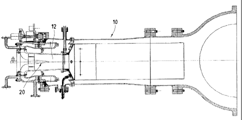
Figure 1 is a longitudinal section through a single combustion chamber,
having a premixing chamber, of a gas turbine with low emission of pollutants,
showing the position of the main liquid fuel injection device according to the
present
invention;
Figure 2 is a longitudinal view, in partial section, of the main injection
device
of Figure 1;
Figure 3 is a plan view of the main injection device of Figure 2;
Figure 4 shows a section of a detail of Figure 2, taken through the plane IV-
IV
of Figure 2;
Figure 5 is an enlarged axonometric view of a detail of Figure 2, showing a
blade for the injection of liquid fuel and cooling air.
With reference to Figure 1, a single combustion chamber, indicated as a whole
by the number 10, of a gas turbine with low emission of pollutants is shown,
the gas
turbine having a premixing chamber 12.
The premixing chamber 12 also has a main liquid fuel injection device 20
according to the present invention, shown in greater detail in Figures 2, 3, 4
and 5.
The main injection device 20 comprises an elongate structure with axial
symmetry, which tapers towards the combustion region within the premixing
chamber
12.
CA 02413635 2002-12-05
72NP06081
More precisely, the device 20 has a base 22, which is generally circular and
is
fixed on the axis of the premixing chamber 12, for example by means of bolts
passing
through a circumferential set of holes 24.
Upstream from the base 22 there is a cylindrical part 40 having a socket 38
for
the entry of cooling air, a socket 39 for the entry of liquid fuel and inlets
37 for fixing
flashback thermocouples, in other words safety devices for detecting flashback
on to
the said injection device 20.
Beyond the base 22, the injection device 20 is tapered through a large-radius
connecting part 26 into an essentially cylindrical portion 28.
After this cylindrical structure 28, the device 20 is tapered again up to a
rounded end 30, which is also described as the "nose".
At the apex of the nose 30, the injector has a hole to allow the cooling air
to
enter the premixing chamber 12. The cooling air is used to cool channels for
the
passage of liquid fuel, thus preventing the formation of carbon residues.
A set of blades 32, consisting of eight blades for example, is provided around
the cylindrical portion 28, the blades being positioned radially with respect
to the axis
of the device 20, at equal intervals.
The blades 32 have a neutral airfoil profile and extend in the axial
direction.
Each blade 32 has, on at least one lateral surface, at least one injection
channel 42 for
the liquid fuel and at least one cooling air injection point 43.
Two flashback thermocouples are provided on the device 20. These
thermocouples are easily installed in the correct position by means of the
guides 36,
shown in Figure 4, which start in the inlet 37 and terminate in the proximity
of the
nose 30.
In a preferred embodiment, these thermocouples are provided both at the
rounded end 30 and on the walls of the chamber 12.
6
CA 02413635 2002-12-05
72NP06081
In one embodiment, described by way of example and without restrictive
intent, there are two thermocouples on the rounded end 30 and four on the
walls of the
chamber 12.
The operation of the main liquid fuel injection device 20 for a single
combustion chamber 10, having a premixing chamber 12, of a gas turbine with
low
emission of pollutants according to the invention is clear fr om what is
described
above with reference to the figures, and is briefly as follows.
The liquid fuel is injected through the blades 32 tangentially, in other words
in
a perpendicular direction with respect to the flow of air passing through the
blades 32.
These blades 32 are located in the main duct of the premixing chamber 12,
which receives air which has been preheated by the compression provided by the
turbine's compressor.
Thus a mixing optimally distributed between liquid fuel and air is achieved
before the entry to the combustion region.
At the same time, the cooling air is injected into the premixing chamber 12,
from each blade 32 and also from the apex of the nose 30, this cooling air
being used
to keep the temperature of the liquid fuel supply channels 42 low, and thus
prevent the
formation of carbon residues.
The cooling air is supplied to the inlet of the socket 38 at stabilized
pressure
and temperature.
The thermocouples, starting with those positioned at the rounded end 30,
detect dangerous flashbacks, and if these are detected they send information
through
transducers to the turbine control unit.
It should be emphasized here that, in combustion chambers used in the prior
art, in order to provide a distribution of the mixing between liquid fuel and
air
comparable to that obtained with the main injection device according to the
present
invention, use is made of multiple combustion chambers or chambers of annular
shape
7
CA 02413635 2002-12-05
72NP06081
with a plurality of injection points, instead of a single combustion chamber
as in the
case to which the present patent application relates.
It should also be emphasized that, where there is a single combustion chamber,
the importance of good distribution of mixing between the liquid fuel and air
becomes
even more critical than in the case of multiple or annular combustion
chambers, and
that the required distribution of mixing can be achieved with the main liquid
fuel
injection device for a single combustion chamber, having a premixing chamber,
of a
gas turbine with low emission of pollutants according to the present
invention.
The above description clearly indicates the characteristics of the main liquid
fuel injection device for a single combustion chamber, having a premixing
chamber,
of a gas turbine with low emission of pollutants, which is the object of the
present
invention, and also makes clear the corresponding advantages, which include:
- reduced pressure oscillations in the combustion chamber and good flame
stability;
- high combustion efficiency;
- an increased average life of the components which are subjected to high
temperatures;
- simple and reliable use;
- protection against the damage caused by the deposition of carbon residues
produced during combustion;
- reduced costs and simpler installation and maintenance, by comparison with
a solution in which a multiple or annular combustion chamber is used according
to the
prior art to provide a distribution of mixing between fuel and air comparable
with that
obtained by providing a device according to the invention.
The main liquid fuel injection device for a single combustion chamber, having
a premixing chamber, of a gas turbine with low emission of pollutants
according to
8
CA 02413635 2002-12-05
72NP06081
the present invention has yielded excellent results in laboratory tests,
providing an
excellent distribution of air and fuel mixing after the device, even when the
position
of the device along the axis is varied slightly.
Additionally, after a few hours of operation of the gas turbine at full load,
no
carbon deposits were found on the blades, and all the injection channels were
found to
be clear and clean.
Finally, it is evident that main liquid fuel injection device for a single
combustion chamber, having a premixing chamber, of a gas turbine with low
emission
of pollutants, designed in this way can be modified and varied in numerous
ways, all
included within the scope of the invention.
Moreover, all the components can be replaced with technically equivalent
elements. In practice, the materials used, as well as the shapes and
dimensions, can be
varied at will according to technical requirements.
The scope of protection of the invention is therefore delimited by the
attached
claims.
9