Note: Descriptions are shown in the official language in which they were submitted.
CA 02413688 2002-12-09
Clarnningi Cartridgie for Panel-Type Products
Field of the Invention
The invention relates to a clamping apparatus for holding and positioning a
plurality
of items and, more particularly, a clamping cartridge for releasably clamping
a
plurality of generally planar objects.
Background of the Invention
There are numerous instances where a series of sheet or panel-type products
need
be transported and/or stored. When all such items are identical, there is
usually no
need to be concerned aver loading and unloading sequences. However, when the
items are not identical, any sequenced access must be predetermined which
usually
entails predetermined loading strategies and, furthermore, random access may
simply not be possible. Moreover, where the items vary in thickness, group
clamping typically requires individual (i.e. time-consuming) adjustment of
respective
clamping mechanisms.
Existing solutions are either cumbersome, inefficient and/or unable to address
all of
the user-defined requirements. These requirements and the challenges were,
mainly, the following:
the ability to load a variety of panel sizes and thicknesses within a given
packaging unit, for example in a custom metal rack;
the ability to access, remove or replace any one or all panels individually,
without affecting the rest of the panels;
the ability to grip and hold the parts (panels) during transport and storage;
user-friendly operating sequences;
reliability and ease of maintenance; and
cost effectiveness.
U.5. Patent No. 2,946,453 describes a supporting rack for automobile
windshields
having a plurality of pairs of posts, half of which are fixed while the other
half are
1
CA 02413688 2002-12-09
associated with a movable frame so as to enable the movable posts to be moved
in
unison against the fixed posts to provide a clamping action therebetween. U.5.
Patent No. 2,953,253 illustrates a windshield carrier having a pair of fixed
parallel
slotted frames for receiving windshields therein. Clamping is effected either
by an
associated pair of movable parallel frames having corresponding slots therein
(Fig. 1) or a series of pressure elements movable through a linkage (Fig. 8).
The
devices of both of these patents have unitary movement of all clamping
elements,
but the fixed spacing structure will only function to clamp the thickest of a
plurality
of planar articles of variable thicknesses.
U.S. Patent No. 4,093,251 discloses a windshield carrier having a plurality of
posts
in two rows. A rotatable friction element is disposed atop each post which can
be
rotated into engagement with the surface of a windshield disposed between
adjacent
posts. The friction elements are individually rotatable. This device has the
capacity
to accommodate a plurality of planar articles of variable thicknesses, but
each
clamping mechanism must be operated independently.
U.S. Patent No. 4,202,452 shows a supporting rack for breakable articles
comprising
a plurality of spaced apart posts in parallel rows. An inflatable tube is
provided on
the exterior of each post and, thus, between adjacent posts. The tube is
inflatable
to contact the articles disposed between the posts in a secure and safe
fashion. This
apparatus has the capacity to accommodate a plurality of planar articles of
variable
thicknesses and is operable to close and release all clamps in unison.
However, the
apparatus requires the hydraulic/pneumatic system to be operating/pressurized
at
all times when clamping is required. Thus, if the system fails, the clamping
function
ceases.
U.S. Patent No. 4,785,936 illustrates a device for holding flat objects, such
as circuit
boards, wherein a plurality of slots are provided in a tray having cooperating
blocks
with ridges moveable relative thereto. In order to accommodate a variety of
thicknesses of boards, resilient cushions are disposed between the ridges
which
2
,. ".m . _. .~-_. ._ e,..«~ ~..._vm , a.n... a , ._m,.. .<Y..v:
..N._(~:~~Vf=.gf t~..It.u,~4~.1ti_2 ~,....r~>y.~mu..mv-~.~,w....mrcmr~~
e~.w.n..,...w. ,.., ..... _.
CA 02413688 2002-12-09
compress to the extent necessary. The device is spring biased in the open
position.
This device has the capacity to accommodate a plurality of planar articles of
variable
thicknesses and is operable to close and release all clamps in unison. Like
with U.S.
Patent No. 4,202,452, this apparatus is open in its relaxed state.
Summary of the Invention
A clamping cartridge is provided which comprises a plurality of clamping
mechanisms
spaced apart on a frame or chassis. The clamping mechanisms are generally
oriented perpendicular to their direction of spacing. The clamping mechanisms
are
of the type which comprise a pair of relatively movable jaws which are biased
together. The jaws are openable by levers which are connectable to or integral
with
the jaws such that when the end of the levers are moved relatively toward one
another, the jaws are caused to open. The actuation levers extend through the
frame where they engage a camming mechanism which is operable to urge together
respective pairs of levers of each clamping mechanism so as to cause the
plurality
of clamping mechanisms to open in unison and to permit the respective pairs of
levers of each clamping mechanism to separate so as to cause the jaws of the
plurality of clamping mechanisms to close or clamp against one or more objects
which may have been placed therebetween.
In the preferred embodiment, the camming mechanism comprises a shaft supported
by the frame in the direction of spacing of the clamping mechanisms and having
thereon a plurality of cam wheels which are fixed to rotate with the shaft.
The cam
surfaces are disposed on the radial sides of the cam wheels rather than on the
circumferential or perimetric edge. The cam surface varies in the axial
direction with
the revolution of the wheel. A pair of oppositely oriented cam surfaces are
provided
for each pair of levers of each clamping mechanism. The pair of cam surfaces
engage the distal ends of the pair of levers of a clamping mechanism. As the
shaft
is rotated, the cam surfaces rotate causing the distance between respective
pairs of
cam surfaces at which the distal ends of the levers are engaged to decrease or
3
CA 02413688 2002-12-09
increase, thereby actuating the ends of the pair of levers inwardly or
outwardly
respectively to open and close the jaws of the clamping mechanism.
Advantageously, the cam surfaces between adjacent clamping mechanisms can be
provided on a single cam wheel for economy of manufacture.
One embodiment of the clamping mechanisms of the invention comprises a
flexible
split cylinder-like spring clamp, assembled with two rigid arms that are
wider, flat
and covered with a protective material (typically rubber dipped) at one end
and
narrower at the other end. The wider ends are designed to grip the product
edge,
while the narrow ends are designed to interface with the cam surface.
The clamps are spaced out for a convenient density and mounted on a support
frame. A plurality of tapered cylindrical cams are placed underneath the
clamps,
inside the frame and on one side of each pair of arms. The cams are mounted on
a
keyed shaft that can be rotated by a handle, wrench ar the like.
The rotation of the shaft turns the cams and thus moves the narrow ends of the
arms against the springiness (bias) of each clamp, opening it. The distance
between
the two gripping ends of each pair of arms is at maximum (opening) when the
cams
have the widest section engaged.
The products) can then be introduced. The product is not designed to be seated
onto the clamping system, but on a separate structure, that will only support
the
panels vertically, without any horizontal grip.
The clamp cartridges) are usually mounted under the floor level of a larger
pack,
or rack, or similar storage system. Only the gripping arms are extended upward
and
above the floor level.
4
CA 02413688 2002-12-09
Once product is inserted between the gripping ends of the opened arms, the
shaft
is rotated 180 degrees and the narrowest portions of the cams are positioned
between the arms, thus relaxing the springiness of the clamp to a mere touch.
The gripping ends of the arms naturally move to grip the product, whatever its
width. If product is not present, the gripping ands of the arms will move to a
light
touch (relaxed position). Although the individual clamps are individually
biased
towards a closed position, the device itself may or may not be normally biased
to a
closed position.
The operating principles that are unique to this invention are described by a
normally closed, spring based clamping action, self-adjusting grip strength,
proportional to the product thickness and simultaneous action on all cartridge
clamps, regardless of product presence.
The main features and advantages are: versatility in typo-dimensional product
sequencing and access patterns, simplicity of operation and ease of
maintenance.
While minimum panel spacing depends on cam-to-cam or spring-to-spring open
position geometry which is a function of maximum thickness and flatness of the
panels, the overall applicability is only limited by scale factors, as they
relate to
industrial means of transport and logistics.
Other features and advantages of the invention will become apparent from the
following description and drawings.
Brief Description of the Drawings
Fig. 1A is a perspective view of the clamping cartridge according to the
preferred
embodiment of the invention in its closedjclamping position;
Fig. 1B is an elevational view of the clamping cartridge of Fig. 1A;
5
CA 02413688 2002-12-09
Fig. iC is a plan view of the clamping cartridge of Fig. 1A;
Fig. 1D is an end view of the clamping cartridge of Fig. 1A;
Fig. 2A is a perspective view of the clamping cartridge according to the
preferred
embodiment of the invention in its open/released position;
Fig. 2B is an elevational view of the clamping cartridge of Fig. 2A;
Fig. 2C is a plan view of the clamping cartridge of Fig. 2A;
Fig. 2D is an end view of the clamping cartridge of Fig. 2A;
Fig. 3A is a plan view of the spring body of one of the clamping mechanisms
shown
in the clamping cartridge of Fig. 1A;
Fig. 3B is a bottom view of the spring body of Fig. 3A;
Fig. 3C is an elevational view of the spring body of Fig. 3A;
Fig. 3D is an enlarged end elevational view of the spring body of Fig. 3A;
Fig. 4A is a side elevational view of one of the clamp arms of one of the
clamping
mechanisms shown in the clamping cartridge of Fig. 1A;
Fig. 4B is an end elevational view of the clamp arm of Fig. 4A;
Fig. 4C is a plan view of the clamp arm of Fig. 4A;
Fig. 5A is a plan view of the support frame of the clamping cartridge of Fig.
1A;
6
CA 02413688 2002-12-09
Fig. 5B is a side elevational view of the support frame of Fig. 5A;
Fig. 5C is an end elevational view of the support frame of Fig. 5A;
Fig. 6A is a perspective view of one of the cam wheels of the clamping
cartridge of
Fig. 1A;
Fig. 6B is an elevational view of the cam wheel of Fig. 6A;
Fig. 6C is a plan view of the cam wheel of Fig. 6A;
Fig. 6D is a side elevational view of the cam wheel of Fig. 6A;
Fig. 7A is a plan view of the cam shaft of the clamping cartridge of Fig. 1A;
Fig. 7B is an elevational view of the cam shaft of Fig. 7A;
Fig. 7C is an end view of the cam shaft of Fig. 7A;
Fig. 7D is an elevational view of an alternate cam shaft having a different
mechanism for its rotation;
Fig. 7E is an end view of the alternate cam shaft of Fig. 7D;
Fig. 8A is a perspective view of the clamping cartridge according to the
preferred
embodiment of the invention in which a number of panel-type articles have been
retained;
Fig. 8B is an elevational view of the clamping cartridge of Fig. 8A;
Fig. 8C is a plan view of the clamping cartridge of Fig. 8A;
7
CA 02413688 2002-12-09
Fig. 8D is an end view of the clamping cartridge of Fig. 8A;
Fig. 9 is a perspective view of a transportation/storage rack illustrating the
use of
the clamping cartridge;
Fig. 10 is an alternate perspective view of the rack generally opposite to
that shown
in Fig. 9;
Fig. 1i is a close-up of one of the rack's side clamping cartridges;
Fig. 12 is a close-up of one of the rack's bottom clamping cartridges;
Fig. 13 is a close-up, perspective end view of the lower portion of the rack;
Fig. 14 is an elevational view of an alternate embodiment of the clamping
cartridge
according to the invention, shown in its closed/clamping; and
Fig. 15 is an elevational view of the alternate embodiment of the clamping
cartridge
of Fig. 14 but shown in its position open/released position.
Detailed Description of the Preferred Embodiment
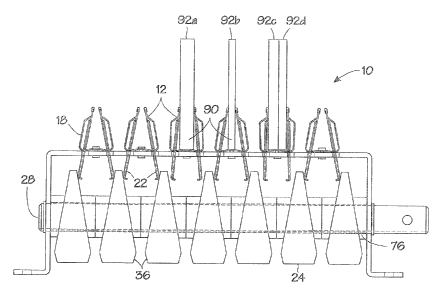
Referring to Figs. 1A-1D, there is shown an exemplary arrangement of the
clamping
cartridge 10 according to the invention. The clamping cartridge 10 comprises a
plurality of spaced apart clamping mechanisms 12 arranged on a chassis or
frame
14. The clamping mechanisms 12 (hereinafter referred to as clamps 12) have a
pair
of clamping arms 16 which cooperate with a spring clip 18 which urges the
upper
ends 20 of arms 16 toward one another in a jaw-like fashion. The lower ends 22
of
the clamping arms 16 project through the frame 14 and act as levers which when
moved relatively toward one another overcomes the spring force of the spring
clip
18 thereby causing the clamp 12 to open (as seen in Fig. 2B). The resiliency
of the
spring clip 18 biases the clamp 12 toward a closed position.
8
CA 02413688 2002-12-09
The clamping cartridge 10 also includes means to actuate (open/close} the
clamps
12 which preferably comprises a series of rotatable cam wheels 24, each of
which
having a cam surface 26 in contact with the lower end 22 of a clamp arm 16.
The
cam wheels 24 are disposed on a rotatable cam shaft 28. Advantageously, the
cam
wheels 24 can be provided with a cam surface 26 on each side, allowing the cam
wheels 24 to be interdigitated between adjacent arms 22a of adjacent clamps
12.
Accordingly, for any number N of Clamps 12, only N+1 cam wheels 24 are
required.
The cam shaft 28 includes an extension 30 which can be used to rotate the cam
shaft 28 and thus cam wheels 24. The extension 30 may be provided with means
to facilitate rotation of the cam shaft 28, such as a knob or handle, or may
include
a lug which can be engaged by a wrench or similar tool. In the embodiment
shown
in Figs. 1A and 2A, a handle 31 is insertable into a transverse aperture 29
(see
Figs. 1B and 2B) to effect leveraged rotation of shaft 28.
The cam surface 26 of the cam wheels 24 is axially and rotationally inclined
such
that by rotating the cam wheels 24, the point of contact with the lower end 22
of
clamp arrn 16 effectively translates axially. The cam surface 26 can be that
which
effectively results from an oblique cutting of a circular cylinder (i.e. a
generally
elliptical surface} as is the case in the preferred embodiment or could be a
helical
surface spiraling oppositely from both ends of the cam wheel (not shown}.
As shown in the preferred embodiment, and in particular in Figs. 6A-6D, the
cam
surfaces 26 are such as to provide the cam wheels 24 with a thinner section on
one
side 32 and a thicker section on the opposite side 34. As seen in Fig, iB, the
thinner
sections 32 of the cam wheels 24 are disposed between the adjacent lower ends
22a
of clamping arms 16 permitting maximum opening between the lower ends 22 of
each clamp 12 and thus minimizing the distance between or closing (depending
on
the spatial relationships} the upper ends 20 of each clamp 12. The outermost
cam
wheels 24a are disposed adjacent the lower end 22b of the outermost clamp arm
16a on outermost clamps 12a. While it is not necessary that the outermost
surface
9
CA 02413688 2002-12-09
26a of outermost cam wheels 24a be a cam surface, manufacturing efficiencies
are
achieved in producing a single or minimum number of cam wheel configurations.
Referring to Figs. 2A-2D, when the cam shaft 28 is rotated such as by handle
31,
the cam wheels 24 rotate so as to cause an increasingly thicker section
thereof to
wedge between adjacent lower ends 22 of adjacent clamps 12, thereby actuating
the clamping arms 16 and thus opening the clamps 12' in unison. Preferably,
the
amount of rotation of cam shaft 28 to effect full opening and closing of the
clamps
12 is 180° (or less). If the cam surface 26b,26c on both halves with of
the cam
wheel 24 is generally the same (i.e. the cam surface 26 is symmetrical about a
vertical plane P as shown in Fig. 6D) then such a design will permit rotation
of the
cam wheel 24 in both directions (clockwise and counterclockwise) with the same
effect.
A transverse chamfer 36 may be provided at the thickest section 34 in which
the
respective lower ends 22 of clamping arms 16 will center and seat when the
clamps
12' reach their fully open position. This allows the clamps to "lock" at or
near their
fully open position to permit items to be inserted into the clamps 12' or
removed
therefrom. The chamfer also permits closer spacing of the clamps 12,
12° and
serves to reduce pressure on the cam wheels 24.
Details of the components of the clamping cartridge 10 are shown in Figs. 3A
to 7D.
Figs. 3A-3D show the spring clip 18 in accordance with preferred embodiment of
the
invention. The purpose of the spring clip 18 in general is to provide biasing
which
urges the clamp 12 toward a closed or clamping position. The spring clip 18
has a
generally U-shaped cross-section as shown in Fig. 3D having a pair of spring
arms
40 separated by a bight 42. It will be appreciated that the spring clip 18 can
be
made in a variety of cross-sectional shapes.
CA 02413688 2002-12-09
The spring clips 18 are fastened to the frame 14 by any conventional means. In
embodiment shown, and pair of holes 44 are provided in the bight 42 while
corresponding holes 44 are provided in frame 14 (see Fig. 5A) through which
appropriate fasteners 48 (see Figs. 1B, 2B and 2C) are used to secure the
spring
clip 18 to the frame 14.
The spring clips 18 are provided with a pair of slots 50 which correspond
generally
with pairs of slots 52 in frame 14 (see Fig. 5A). The slots 50 accommodate and
help
retain spring arms 16 while the slots 52 permit the spring arms 16 to extend
through the frame 14 (as shown best in Fig. 1B). Preferably, the tips 54 of
the
spring arms 40 are sufficiently close such that when both clamping arms 16 are
disposed within slots 50, the upper ends 20 of the clamping arms 16 are biased
together. In Fig. 1B, the upper ends 20 of the clamping arms 16 are shown
slightly
separated. This is due to the fact that the insertion of the thinner sections
32 of the
cam wheels 24 causes a slight pressure on the lower ends 22 of the clamping
arms
16, thus causing the slight separation. Preferably, the spring clips 18 are
made from
known elastic materials such as spring steel.
Figs. 4A-4C show one of the spring arms 16 of the clamp 12. The upper- ends 20
may be relatively wider than the lower ends 22 to provide extended
clamping/gripping support along a portion of the product edge. In this regard,
the
upper ends 20 may be covered or coated with a protective, high-friction
material to
reduce possible damage to the product to be clamped and to increase the
clamp's
gripping capability. For example, the upper ends 20 may be dipped in a liquid
settable rubber compound. The lower ends 22 are designed to interface with the
cam surface and thus may be provided with a rounded edge 56 to enable slippage
to a certain extent. Preferably, the spring arms 16 are made from relatively
stiff
materials, such as stamped steel, so as to reduce the amount of bending over
the
force range expected to be encountered.
11
CA 02413688 2002-12-09
The frame 14 is shown in detail in Figs. 5A-5C. The frame 14 provides the
basic
supporting structure for the clamps 12 and cam shaft 28 (as shown in Fig. 1B).
Thus the frame 14 may be conveniently made by bending an appropriate sheet
material into a three sided, rectilinear configuration having an elongated
central
section 60 and two end sections 62. As aforesaid, the central section 60
includes
holes 44 by which the clamps 12 are affixed thereto by fasteners 48 and slots
50
through which the clamping arms 16 of the clamps 12 extend. The end sections
62
each include an aperture 64 in which the cam shaft 28 can be journaled or in
which
a bearing for the cam shaft 28 can be provided. The frame 14 may also include
mounting flanges 66 which include holes 67 for mounting the cartridge 10 where
desired. While the preferred frame 14 has been shown with open sides 68 which
reduces material costs and facilitates manufacturing thereof, the sides 68 can
be
closed where it is desired to restrict access to the cam wheels 24 or to
inhibit ingress
of dust and other foreign matter into the working components of the cartridge
10.
The cam wheel 24 is shown in detail in Figs. 6A-6D. When viewed along its axis
(Fig. 6D), the cam wheel 24 has an outer circular configuration. The cam wheel
24
includes a central bushing 70 and an aperture 72 by which the cam wheel 24 can
be
mounted on the cam shaft 28. The aperture 72 includes a keyway 74 for
accommodating a key 76 (see Fig. iB) associated with the cam shaft 28 to
prevent
the cam wheels 24 from rotating relative to the cam shaft 28. The cam angle 8
is
generally a function of the diameter of the cam wheel 24 and the desired
longitudinal movement of the lower ends 22 of the clamping arm 16 (to effect a
correspondingly opposite proportional movement of its upper end 20 and hence
an
opening of the clamp 12).
Preferably, the cam wheels 24 are individual and identical for greater
manufacturing
efFciency and flexibility. Depending on the length of bushing 70, a cam wheel
24
may abut the bushing 70 of an adjacent cam wheel 24 (as shown in Fig. 1B) or
may
be relatively free to move along the keyed cam shaft 28, there being a certain
degree of self-centering/alignment on account of the clamping arms in the
latter
12
CA 02413688 2002-12-09
case. Still, if spacing between cam wheels becomes significant, (required by
panel
separation and/or clamp size), washers may be introduced, as a precaution or
as a
visual enhancement, although they may not be required for the operability of
the
device. Alternatively, the cam wheels may be made integrally with one another.
The cam wheels 24 may be made from any suitable material such as metal (steel,
aluminum, etc.), hard plastics, TefIonT"', etc. and they can be machined,
stamped,
injection molded, or any other suitable method of manufacture. The material
should
provide mechanical robustness, and a reasonable fife-time under friction. The
materials for the cam wheels 24 and the contacting portion of the clamping
arms 22
can be chosen to have a suft=ICiently high coefficient of friction such that
the cam
wheels 24 will remain in whatever position they are in when rotation of the
shaft is
stopped (which may or may not be at top or bottom dead center). Alternatively,
the
chosen materials can have a sufficiently tow coefficient of friction whereby
the
pressure exerted by the clamping arms 22 on the camming surfaces 26 causes the
cam wheels 24 to rotate toward the clamp closed position, thereby resulting in
a
clamping cartridge which is normally biased in the closed position.
Lastly, the cam shaft 28 is detailed in Figs. 7A-7C. The shaft 28 has two
annular
grooves 80 spaced apart slightly greater than the distance between end
sections 62
of frame 14 for accommodating retaining rings 82 (as shown in Fig. 1B). The
shaft
28 has a keyway 84 which cooperates with key 76 (as shown in Figs. 1B and 1D)
to
enable rotation to be imparted from the shaft 28 to the cam wheels 24.
Alternatively, a splined shaft could be provided with the apertures in the cam
wheels
being correspondingly splined. The shaft 28 may be made from any suitable
material typically used for shafts.
Figs. 7D and 7E illustrate an alternate mechanism for assisting in the
imparting of
rotational movement in the form of a lug 29' which is provided on the
extension 30'
of alternate shaft 28'. A wrench (not shown) is engageable with the lug 29'
for
rotating the shaft 28'. Any other known mechanism could likewise be employed
for
manual rotation of the shaft or a power-driven device could easily be
substituted.
13
CA 02413688 2002-12-09
Referring to Figs. 1B, 2B and 8A-8D, to operate the clamping cartridge 10, the
cam
shaft 28 is rotated by the handle means 31, which causes the cam wheels 24
which
are keyed to the cam shaft 28 by key 76 to rotate. As the section of the cam
wheel
24 disposed between adjacent clamps increases in thickness, relatively
speaking, or
alternatively, as the distance between the upper ends of adjacent cam wheels
24
decreases, the clamps 12 are urged toward an open position 12' but remain
biased
against the force of the spring clips 18. As the cam shaft 28 rotates to
180°, the
lower ends 22 of the clamping arms 16 self-center against the chamfered edge
36
of the cam wheel 24, thereby retaining the clamping cartridge 10 in its open
position. In the cartridge's open position as shown in Fig. 2B, the individual
clamps
12' are open to receive a portion of the edges) 90 of the panel-like objects)
92
(shown schematically). One or more panels 92 (having a total thickness less
than
the design width of the open clamp 12') are positioned in one or more of the
open
clamps 12' and the cam shaft 28 is again rotated (either through to
360° or back to
0°) to close the clamps 12 against the inserted panels) 92. Since each
of the
clamps 12 are individually biased toward a closed position, the clamps 12 will
naturally adjust to the thickness of the retained panels) 92 as shown best in
Fig.
8B. Accordingly, the clamping cartridge 10 can accommodate a series of
different
panels comprising panels of different thicknesses 92a,92b and/or a varying
number
of panels 92c,92d of same or different thickness within each clamp 12, as
shown in
Figs 8A-8D. This will permit variability in loading or unloading (i.e. random
access)
and typo-dimensional sequencing for products retained within the clamping
cartridge
10. When release or removal of one or more panels 92 is desired, the cam shaft
28
is rotated 180° in the same manner as aforesaid to open the clamps 12
in unison.
When the desired panels have been removed, the cam shaft 28 can be actuated
again to close clamps 12 against the remaining panels.
The clamping cartridge 10 can be used in a variety of storage and/or packaging
systems. The cartridges can be used in a variety of containers like hard
(plastic)
bins, totes, wooden and even paper (cardboard) structures, as well as on
carts,
cars, dollies, elevators, conveyors, or in fixed applications (on walls, on
floors, on
14
CA 02413688 2002-12-09
structures of any kind). In one such application shown in Figs. 9-13, a glass-
panel
storage rack 100 is realized comprising a frame 102 to which a generally
horizontal
bottom support 103a and a generally vertical side support 103b are attached.
At
least one clamping cartridge 10 is preferably provided in association with
each
support 103a,103b such that the clamping mechanisms 12a of the horizontal
support cartridges) 10a align in the same plane with the corresponding
clamping
mechanisms 12b of the vertical support cartridges) 10b. The clamping
cartridges
lOa,lOb can then be opened as aforesaid so as to enable the edges 104a,104b of
glass panels 105 to be positioned within the clamps 12a,12b, respectively. The
clamping cartridges 10a,10b can then be closed as aforesaid so as to
clampingly
retain the glass panels 105 within the rack 100.
When any one of the glass panels 105 is to be removed, the clamping cartridges
lOa,lOb are opened and the panels 105 can be removed as desired. Although when
the clamping cartridges 10a,10b are opened, all of the clamping mechanisms
release, the edges 104a,104b of glass panels 105 are still bounded by the
clamping
arms 16 (jaws) and thus the panels 105 should remain in place until removed.
However, it may be desirable to incline the rack 100 to take advantage of
gravity to
ensure the panels 105 stay in the rack 100 when the clamping cartridges
10a,10b
are opened. In the embodiment shown in Figs. 9-13, the frame 102 is maintained
generally upright while the bottom and side supports 103a,103b are tilted as
shown
by angle a in Figs. 9, 10 and 13.
The rack 100 may also include separate seating/supporting devices 106 (shown
best
in Figs. 11, 12 and 13) for the panel whereby the weight of the panels is
supported
thereby. The clamping cartridges 10a,10b are positioned such that the jaws 20
are
engageable with the edge portion 104a,104b of the panels 104 without the
panels'
weight resting on or abutting against the bight 42 of the clamps 12 as shown,
for
example, in Fig. 11. In this regard, the rack 100 separates the
gripping/clamping
task/function from the gravitational, supporting functions. The use of
separate
seating/supporting devices 106 reduces the need for more robust clamps and
CA 02413688 2002-12-09
provides more economical cushioning and surface distribution capability versus
having it built into the clamps. As shown, the seat/supports 106 have a
multiple-U-
shaped cross-section seen best in Fig. 13, which is attachable to convenient
locations on the bottom and side supports 103a,103b, wherein the parallel
channels
108 are aligned generally with the clamps 12 of the clamping cartridges 10. In
the
case of the lower seat/supports 106a on the bottom support 103x, the edge
bearing
surfaces 110 extend above the bights 42 of the clamps 12 of the cartridges 10a
but
not above the upper ends of the arms 20, whereas the edge bearing surfaces 110
of the side seat/supports 106b on the side support 103b, extend inwardly of
the
bights 42 of the clamps 12 of the cartridges lOb but not beyond the upper ends
of
the arms 20.
Depending on the arrangement of clamping cartridges 10 and seat/supports 106
in
a given rack 100, it may be possible to use the rack 100 to store or transport
not
only a plurality of identical articles, but also differing articles. As can be
seen in
Figs. 9 and 10, different sets of glass panels 105a,105b,105c are retained in
the rack
100 although only three of the four clamping cartridges 10 are used, only two
of
which are common to all sets of glass panels 105a,105b,105c. Fig. 12 shows how
the seat/supports 106 cradle the remote (from the clamps) edges 104c of the
glass
panel 105c. Depending on the clamping strength and the article to be clamped,
it
may only be necessary to employ one clamp 12 per article (hence a single
clamping
cartridge 10) and, where necessary, utilize one or more aligned seat/supports
106
to support and prevent movement of non-clamped edges.
The seat/supports 106 can be made of any appropriate material bearing in mind
the
articles expected to be transported or stored in the rack 100. As shown, the
seat/supports 106 are made from an extruded plastics material.
Advantageously, the bottom and side supports 103a,103b can comprise a
plurality
of slats 112 on which the clamping cartridges and seat/supports 106 are
mounted.
By having the slats 112 moveable/adjustable with respect to the frame 102 and
16
CA 02413688 2002-12-09
hence the spacing between adjacent clamps, the rack 100 can readily be adapted
to accommodate a wide variety of articles.
Depending on the number of clamping cartridges employed in any one rack and
their
accessibility, it may be advantageous to provide a linkage mechanism (not
shown)
to operate them simultaneously or to utilize power-driven shafts with an
associated
control unit (not shown) to selectively rotate the shafts individually or
simultaneously.
The individual biasing of the clamps 12 can be achieved in a number of ways as
is
known in the art. The embodiments shown herein employ a clip-type spring
although this is not to be considered limiting. The positioning of the spring
clip 18
in the aforementioned embodiments is shown to be above the frame 14. However,
depending on the nature of the spring or biasing mechanism being used,
positioning
can be varied just so long as the function remains.
Instead of having the jaws of the clamp used to clamp 'the article and the
clamping
arms (levers) bearing on the camming surface of the cam wheels, the clamps can
be reversed such that the jaws engage the opposed camming surfaces of the cam
wheel and the articles are then clamped between adjacent clamping arms of
adjacent clamps as shown in the alternate embodiment illustrated in Figs. 14
and
15. The alternate clamping cartridge 120 shares many of the same components as
the clamping cartridge 10 of Fig. 1A, such as the cam shaft 28 and associated
cam
wheels 24. The frame 122 is similar but its dimensions may require alteration
to
accommodate the clamps 124 in their reverse orientation. The clamps 124 are
disposed such that their spring clips 126 are beneath the frame 122 and with
their
arms 128 extending thereabove through the slots 130 in the frame 122. The thin
section 32 of the cam wheels 24 are positioned between the jaws 132 of the
clamps
124 such that the tips 134 of the clamping arms 128 engage the opposed camming
surfaces 26 of the cam wheels 24. As the shaft 28 is rotated, the portion of
the cam
wheels 24 between the jaws 132 becomes increasingly thicker, relatively
speaking,
17
. . , r . .. . ".., ."., .. . xx,z .".M,_. ~~, . .. .:~. ~,. . _ ~ . . ~ ~ ..~
~.~w~ M . .~. ~,~..~.W,una rv~.~.~ ~ _~
CA 02413688 2002-12-09
causing the distal ends 136 of the arms 128 of each clamp 124 to move
relatively
toward one another and hence away from the distal end 136 of the adjacent arm
128 of the adjacent clamp 124. Continuing the rotation to 180° as shown
in Fig, 15,
the jaws 132 over-center onto the chamfers 36 to "lock" into an opened
position.
Panels 140 which may have been disposed between adjacent arms 128 of adjacent
clamps 124 are then removable. Alternately, panels 140 may be situated between
adjacent arms 128 of adjacent clamps 124 whereupon rotation of the shaft 28
(either through to 360° or back to 0°) returns the thinner
section 32 of the cam
wheels 24 to between the jaws 132, relaxing/reducing the tension on the spring
clips
126, and reducing the distance between the distal ends 136 of the adjacent
arms
128 of the adjacent clamps 124, which effectively permits them to act as
clamps.
The outermost clamps 124a,124b as shown in Fig. 14, may include only one
clamping arm 128a,128b, respectively, as an outermost clamping arm 128c, shown
in phantom, would be unnecessary in this arrangement. However, an outermost
arm 128c could be provided. It can be seen that the alternate clamping
arrangement 120 requires the same number of clamps 124 as cam wheels 24.
However, the number of cam wheels 24 is still one greater than the number of
clampable articles 140 as the clamping function is based on the spacings
between
adjacent clamps 124.
While there has been shown and described herein a clamping cartridge for panel-
type products and a rack for its application, it will be appreciated that
various
modifications and or substitutions may be made thereto without departing from
the
spirit and scope of the invention.
18
...._... ....,..."..a r , >. rmu . ., rixcwm ... c, 1 S . . ':F) t..
~~d.~..:..wf,.d'G7C'<"F,..:..Lri':,.."%FYfrtv4aVx m..iWW,.wA..,.,
A).M..T7~,.x; o.~ wn3.anw.....> ..,m..,." r~rtmr!e rcs.-> vmmv.,«.."a._
>wn....a~e... x-.- ...... ..rxi_...,