Note: Descriptions are shown in the official language in which they were submitted.
CA 02413745 2003-O1-06
WO 02/33215 PCT/GBO1/04619
WELL CONTROL
This invention relates to well control, and in
particular to a method and apparatus for use in controlling
access and flow to and from a subsurface well.
Zn the oil and gas exploration and production
industry, bores are drilled to access subsurface
hydrocarbon-bearing formations. The oil or gas in the
production formation is under pressure, and to prevent
uncontrolled flow of oil or gas from the formation to the
surface, that is a "blowout", it has been conventional to
fill the bore above the formation with fluid of cuff icient
density that the hydrostatic pressure head provided by the
column of fluid retains the oil or gas in the formation.
However, ~t has been recognised that this practice may
result in damage to the formation, and may s~.gnifioantly
IS reduce the productivity of the formation. This problem has
recently corns to the fore as deeper and longer bores are
drilled, and thus th.e hydrostatic pressure of drilling
flua.d or "'mud" increases, and further as the pressures
necessary to circulate drilling Fluid and entrain: cuttings
2(J in the conventional manner increases.
CA 02413745 2003-O1-06
WO 02/33215 PCT/GBO1/04619
7
One result of these experiences and findings has been
the development of technology and methods which permit
"under-balanced" drilling, that is a drilling operation in
which the pressure of the drilling fluid is lower than the
formation fluid pressure, such that oil and gas may flow
from the formation and commingle with the drilling fluid.
The fluids travel together to the surface and are separated
at surface. In many cases, use of underbalanced drilling
has resulted in marked increases ~n well productivity.
However, one difficulty associated with underbalanced
drilling is the relatively high fluid pressures that axe
experienced at surface. This places an increased reliance
on surface sealing arrangements, and generally increases
the difficulty in controlling the well; the conventional
high density fluid column is not present, and in the event
of difficulties, pumping higher density fluid into the well
to "kill" or control the well may take some time and is
likely to result in damage to the formation, perhaps to an
extent where the well must be abandoned.
There is also a difficulty associated with making up
drill string and the like to be run into such wells, or
indeed in any well! where the pressure at surface is
relatively high. In such wells, the relatively high fluid
CA 02413745 2003-O1-06
WO 02/33215 PCT/GBO1/04619
3
pressure (which may be several hundred atmospheres) will
tend to push the drill string up and out of the well, such
that making up such a string becomes a difficult and
potentially dangerous operation. This difficulty persists
S until the weight of the string is sufficient to counteract
the pressure force.
It has been proposed to avoid or overcome at least
some of these difficulties by placing a flapper valve in a
lower section of a well, the valve closing when the
pressure forces acting from below the valve are greater
than the pressure forces acting from above the valve. This
places restrictions of the placement of the valve which, to
be effective, must be located close to the pressure balance
point in the well, that is the point where the upward
acting fluid pressure force, or reservoir presSUre, equals
the downward acting force from the pressure head produced
by the column of fluid in the bore. Further, while such a
valve may assist in prevent2ng uncontrolled flow from a
formation, the valve will not serve to protect a formation
?0 from damage or contamination in the event that the pressure
above the valve rises; ~n such a situation elevated
pressure above the valve will tend to open the valve.
Similarly, testing the valve presents difficulties, as
CA 02413745 2003-O1-06
WO 02/33215 PCT/GBO1/04619
higher test pressures will tend to open the valve, and
therefore no pressure greater than reservoir pressure may
be safely utilised, as a higher pressure would run the risk
of damaging the formation.
It is among the objectives of embodiments of the
present invention to obviate or mitigate these
disadvantages.
According to one aspect of the present invention there
is provided a method of isolating a reservoir of production
l0 fluid in a formation, the method comprising:
providing a valve in a bore intersecting a production
formation and irl which the hydrostatic pressure in the bore
at the reservoir is normally lower than the formation
pressure; and
controlling the valve from surface such that the valve
will only move from a closed configuration to an open
configuration on experiencing a predetermined differential
pressure thereacross.
The invention also relates to an apparatus for use in
isolating a reservoir of production fluid ~.n a formation,
the apparatus comprising:
a valve adapted for location in a bore intersecting a
production fc~rmatiorr. and in which the hydrostatic pressure
CA 02413745 2003-O1-06
WO 02/33215 PCT/GBO1/04619
in the bore at the reservoir is normally lower than the
formation pressure;
first valve control means fox permitting control of
the valve from surf ace; and
second valve control means fox permitting control of
movement of the valve from a closed to an open
configuration in response to a predetermined differential
pressure across the valve.
Preferably, the valve is controlled such that it will
only open when there is little or no pressure differential
across the valve. Thus, as the valve opens there is little
if any flow of fluid through the valve as the pressure
equalises; opening the valve in the presence of a pressure
differential may result in the rapid flow of fluid through
the valve as it opens, with an increased likelihood of
erosion and damage to the valve. Tn under-balanced and
live well applications this a2lows the valve to hold
pressure from one ox both sides, and minimises the risk of
formation damage or contamination when the pressure above
the valve is higher than the pressure below the valve.
Further, this feature may be utilised to minimise the xis~
of uncontrolled flow of fluid from the formation, in the
event of pressure below the valve being higher than the
CA 02413745 2003-O1-06
WO 02/33215 PCT/GBO1/04619
pressure above the valve.
The valve may be positioned above, at or below the
pressure balance point.
Preferably, the valve is controlled from surface by
fluid pressure, the control fluid supply of gas or liquid
being isolated from the well fluid, for example in control
lines or in a parasitic annulus. The valve may include a
control fluid piston, application of control fluid thereto
tend~.ng to close the valve. Preferably, the valve is
further also responsive to well fluid pressure, and in
particular to the differential well fluid pressure across
the valve, such that the closed valve will remain closed or
will open in response to a selected control pressure in
combination with a selected differential pressure. The
valve may include a piston in communication with fluid
below the valve and a piston in commun~cat~.on with fluid
above the valve; application of pressure to the former may
tend to close the valve, while application of pressure to
the latter rnay tend to open the valve. zn a preferred
?~ embodiment, a selected first control pressure w~.11 close
the valve. Such a first control pressure ~n combination
w~.th a higher pressure below the valve will tend to
maintain the valve closed. further, ~r~c~reas~.ng the control.
CA 02413745 2003-O1-06
WO 02/33215 PCT/GBO1/04619
7
pressure w211 maintain the valve closed in response to a
higher pressure above the valve. This fac~.lity also allows
the applied control pressure to be brought to a particular
value, the pressure differential across the valve to be
minimised and the control fluid pressure then varied to
allow the valve to open.
Preferably, the valve is a ball valve. However, the
valve may also be a flapper valve, or indeed any form of
valve appropriate to the application.
Preferably, the valve comprises two valve closure
members, which may be two ball valves, two flapper valves,
or even a combination of different valve types. The valves
may have independent operating mechanisms. The valve
closure members rnay close simultaneously, or in sequence,
and preferably the lowermost valve member closes first.
This allows the valves to be pressure-tested individually.
Sequenced closing may be achieved by, for example,
providing the valve rnernbers in combination with respective
spring packs with different pre-loads.
?0 Preferably, the valve is run into a cased bore on
intermediate or parasa~ti.c casing, thus defining a parasitic
annulus, between the existing casing and the parasitic
cas~.ng, via which control pressure may be communicated to
CA 02413745 2003-O1-06
WO 02/33215 PCT/GBO1/04619
the valve. The parasitic casing is sealed to the bore-
lining casing at or below the valve, typically using a
packer or other sealing arrangement. The parasitic annulus
may be used to carry fluids, for example to allow nitrogen
injection in the well below the valve. For example,
additional casing may be hung ofd below the valve to extend
the parasitic annulus, and a pump open\pump closed nitrogen
injection valve provided to selectively isolate the
parasitic annulus from the well bore annulus. Tn other
embodiments the parasitic annulus may be utilised to carry
gas or fluid lift gas or fluid to a point in the well above
the valve, or even between a pair of valves. One or more
one-way valves may be provided and which may be adapted to
open at a parasitic pressure in excess of that required to
close the valve or perform pressure tests above the valve.
Such an arrangement may be utilised to circulate out a
column of well 7~i11 fluid, prior to opening the valve, or
alternatively to inject a fluid slug prior to opening the
valves, or to inject methanol from the parasitic annulus to
prevent hydrate formation.
The valve may be configured to allow the valve to be
locked open, for example by locating a sleeve in the open
valve.
CA 02413745 2003-O1-06
WO 02/33215 PCT/GBO1/04619
The valve may be configured to permit pump-though,
that is, on experiencing a sufficiently high pressure from
above, the valve may be moved, for example partially
rotated in the case of a ball valve, to permit fluid flow
around the nominally closed valve.
According to another aspect of the present invention
there is provided an apparatus for use in isolating a
reservoir of production fluid in a formation, the apparatus
comprising:
a valve adapted for location in a bore 2ntersecting a
production formation and in which the hydrostatic pressure
in the bore at the reservoir is normally lower than the
formation pressure; and
first valve control means for permitting control of
the valve from surface,
the valve including two valve closure members, both
valve closure members being adapted to hold pressure both
from above and from below.
Preferably, the valve closure members are ball valves .
2p Alternatively, the valve closure members are flapper
valves.
Preferably, the valve closure members are
independently operable.
CA 02413745 2003-O1-06
WO 02/33215 PCT/GBO1/04619
These and other aspects of the present invention will
now be described, by way of example, with reference to the
accompany2ng drawings, in which:
Figure 1 is a schematic illustration of apparatus for
5 use in isolating a reservoir in accordance with a preferred
embodiment of the present invention, shown located in a
well;
Figure 2 is an enlarged sectional view of valves of
the apparatus of Figure 1; and
10 Figure 3 is a further enlarged sectional view of one
of the valves of the apparatus of Figure 1.
Reference is first made to Figure 1 of the drawings,
which is a schematic illustration of apparatus 10 for use
in isolating a reservoir in accordance with a preferred
embodiment of the present invention, the apparatus 10 being
shown located in a well 12. The illustrated well features
three main sections, that is a 17~/ inch diameter hole
section lined with 133/s inch diameter casing, a 121 inch
hole section lined with 951a inch casing, and an 8% inch hole
section lined with 7 inch casing; those of skill in the
art will of course recognise that these dimensions are
merely exemplary, and that the apparatus 10 may be utilised
in a wide variety of well configurat~..ons. The apparatus 10
CA 02413745 2003-O1-06
WO 02/33215 PCT/GBO1/04619
is located within the larger diameter first well section
and comprises upper and lower valves 14, 16. As will. be
described, the valves ~4, 16 are similar, with only minor
differences therebetween. The valves are mounted on tubing
18 which extends from the surface, through a rotating blow-
out preventer (BOP) 20, an annular preventer 22, and a
standard BOP 24. An intermediate tubular connector 26
joins the valves 14, 16, and a further section of tubing 28
extends from the lower valve 16, through the 9~/8 inch
casing, to engage and seal with the upper end of the 7 inch
casing. Thus, an isolated annulus 30 is formed between the
valves 14, 16 and the tubing 18, 28, and the surrounding
casing; this will be referred to as the parasitic annulus
30.
The apparatus 10 will be described with reference to
an under-balanced drilling operation, and in such an
application. a tubular drill string will extend from surface
through the valves ~4, 16 and the tubing 18, 28.
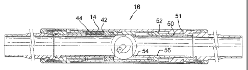
Reference is now also made to Figure 2 of the
Q drawings, which is an enlarged sectional view o~ the valves
14, 16, shown separated. Reference wall also be made to
Figure 3 of the drawings which is an enlarged sectional
view of the lower valve 1~. As the only differences
CA 02413745 2003-O1-06
WO 02/33215 PCT/GBO1/04619
between the valves 1~, 16 is the pre-loading on the valve
closing spring and the arrangement of porting for valve
control fluid, only one of the valves 16 will be described
in detail, as exemplary of both. The valve 16 is a ball
valve and therefore includes a ball 34 located within a
generally cylindrical valve body 36, and in this example
the ends of the body 36 feature male premium connections 38
for coupling to the tubing section 18 and the connector 26.
The ball 34 is mounted in a ball cage 40 which is
axially movable within the valve body 36 to open or close
the valve. The valve 16 is illustrated in the closed
position. Above the cage 40 is an upper piston 42 which is
responsive to fluid pressure within the tubing 18 above the
valve 14, communicated via porting ~3. Further, a power
spring 44 is located between the piston 42 and a top plate
~6 which is fixed relative to the valve body 36.
Accordingly, the spring 44, and fluid pressure above the
ball. 34, will tend to move the valve ball 3~ to the open
position.
?p Below the cage 4Q is a lower piston 48 which, in
combination with the valve body 36, defines two piston
areas, one 5t? in fluid communication with the parasitic
annulus 30, via porta..n~ 52, and the other ~2 in
CA 02413745 2003-O1-06
WO 02/33215 PCT/GBO1/04619
13
communication, via porting 53, with the tubing below the
valves 14, 16, that is the reservoir pressure.
In use, in the absence of any pressure applied to the
valves 14, 16 via the parasitic annulus 30, the springs 44
will urge the valve balls 34 to the open position, allowing
flow through the valves 14, 16. If however it is desired
to close the valve, the pressure in the parasitic annulus
30 is increased, to increase the force applied to the
parasitic pistons 50. The pre-load on the sprang 44 in the
lower valve 16 is selected to be lower than the pre-load of
the spring 44 in. the upper valve 14 , such that the lower
valve 16 will close first. Thus, the effectiveness of the
seal provided by the lower valve 16 may be verified. A
further increase in pressure in the parasitic annulus 30
will then also close the upper valve 14.
The valve balls 3~ are designed to permit cutting or
shearing of lightweight supports such as slickline,
wireline or coiled tubing, passing through the apparatus
10, such that the valves may be closed quickly in an
emergency situation without having to withdraw a support
form the bore.
With the valves 14, 16 closed, the reservoir is now
isolated from the ~,~pper section of the well! . This
CA 02413745 2003-O1-06
WO 02/33215 PCT/GBO1/04619
l~
facilitates various operations, including the retrieval,
making up and running in of tools, devices and their
support strings above the apparatus 10, or the circulation
of fluids within the upper end of the tubing 18 to, for
example, fill the tubing 18 with higher or lower density
fluid.
In the event that the reservoir pressure below the
valves 14, 16 is higher than the pressure in the tubing 18
above the valves 16, 18, the reservoir pressure acting on
the pistons 52 will tend to maintain the valves 14, 16
closed, thus preventing uncontrolled flow of formation
fluids from the reservoir.
In the event that the pressure differential is
reversed, that is the pressure force above the valves 14,
16 is greater than the reservoir pressure acting below the
valves 14, 16, the parasitic pressure may be increased to
increase the valve closing force acting on the pistons 50,
to counteract the valve opening force acting on the pistons
42.
?0 The area of the upper piston ~2 is equal to the
combined areas of the parasit~~..c and reservoir pistons 50,
52, while the parasitic piston 50 is larger than the
reservoir piston. 52. Thus, ~f it ~..s desired to open the
CA 02413745 2003-O1-06
WO 02/33215 PCT/GBO1/04619
l~
valve from a closed position, this is normally achieved by
increasing the pressure in the parasitic annulus 30 to a
point where the parasitic pressure is substantially similar
to the reservoir pressure. The pressure in the tubing 18
is then increased, and as the tubing pressure approaches
the reservoir pressure the forces acting on the pistons 42
reach a level similar to the oppositely acting forces on
the lower pistons 48, such that the springs 44 will tend to
open the valves when the parasitic pressure is vented at
surface .
While the parasitic pressure remains vented, the
springs 44 will retain the valves open.
With this arrangement it would be possible to open the
valves when the tubing pressure above the valves 14, 16 was
lower than reservoir pressure, if the parasitic pressure
was not increased to be greater or equal to the reservoir
pressure. However, this would result in the valves l~, 16
opening with a pressure differential, and the resulting
rapid flow of fluid through the valves would bring an
?0 increase likelihood of erosion and damage to the valves and
upstream equipment.
In the event that one or both of the val~res cannot be
opened, and it is desired to, far example, ~~2cill~~ the well,
CA 02413745 2003-O1-06
WO 02/33215 PCT/GBO1/04619
16
if sufficient tubing pressure is applied from surface the
valve balls 34 will be pushed downwardly to an extent that
kill fluid may pass around the balls 34 and then out of
pump-through ports 54 provided in the lower ball seats 56.
If desired, one or more one-way valves may be provided
in the tubing 28 or valve body 36. For example, one or
more one-way pressure relief valves may be provided above
the upper valve 14, and configured to pass gas or fluid
from the parasitic annulus into the tubing 18. Such a
valve positioned just above or between the valves 14, 16
may be used to, for example, circulate out a column of well
kill fluid prior to opening the valve, or to inject a fluid
slug prior to opening the valves. Such a valve could also
be used to inject methanol from the parasitic annulus 30 on
l.5 top of the upper valve 14 to prevent hydrate formation.
Alternata.vely, a one-way valve could be incorporated
between the valves 14, 16. Of course, such a valve or
valves would only open in response to a parasa.tj..c annulus
pressure in excess of that required to close the valves, to
?Q perform a pressure test from above a closed valve, or to
support a column of well kill f~ui.d above the valves.
In the il~.ustrated embodiment the prov~,siora. of the
parasitic annulus may also be used to advantage to, for
CA 02413745 2003-O1-06
WO 02/33215 PCT/GBO1/04619
17
example, allow nitrogen injection in the well below the
apparatus 10. For example, a nitrogen injection point
could be provided on the tubing 28 below the apparatus 10.
Of course the injection point would have to be isolated
from the tubing bore using a pump open\pump close nitrogen
injection valve.
From the above description it will be apparent to
those of skill in the art that the apparatus described
above provides a safe and convenient method of isolating a
reservoir, and the ability o~ the valves to hold pressure
from both above and below is of considerable advantage to
the operator, and provides additional safeguards and
convenience in under-balanced drilling, at balance drilling
or live well\light weight intervention environments, most
particularly in the deployment of drilling assemblies,
intervention assemblies, workover assemblies, completions,
liners, slotted liners or sandscreens.
Those of skill in the art will also recognise that the
illustrated embodiment is merely exemplary of the present
?0 invention, and that various modifications and improvements
may be made thereto without departing from the scope of
invention. For example, rather than controlling the
operation of the valves ~.~, l~ via thp parasitic an~:ulus
CA 02413745 2003-O1-06
WO 02/33215 PCT/GBO1/04619
1$
30, conventional control lines may be run from surface to
supply control fluid to the valves. Further, rather than
providing valves in individual housings, a common housing
assembly for both valves could be provided. The above
described valve arrangements rely primarily on metal-to-
metal seals between the balls and the valve seats, and of
course in other embodiments elastomeric seals may also be
provided. The valves illustrated and described above are
in the form of ball valves, though those of skill in the
art will recognise that flapper valves may also be
utilised, particularly flapper valves having the facility
to be held closed in response to both pressure from above
and from below.