Note: Descriptions are shown in the official language in which they were submitted.
CA 02413765 2002-12-10
DETECTION OF SMALL HOLES IN LAMINATES
TECHNICAL FIELD
This -invention relates to detec'.ion of small holes in laminates.
BACKGROUND
Composite laminates of textile materials, for example, often include a barrier
film to
prevent the passage of liquids and gases through the laminate. In addition to
the barrier film,
these barrier laminates include other layers such as foams, fabrics,
nonwovens, and breathable
films.
Examples of barrier laminates include waterproof breathable laminates,
breathable
chemical protection laminates, viral protection laminates, mold-in-place
laminates, and allergy
proof and fluid proof laminates. Generally these laminates are manufactured-by
using heat,
pressure and/or adhesives to adhere layers of the laminate together.
To function properly as a barrier, these laminates generally must be non-
porous, i.e., free
of even small holes. For example, to form a fabric-covered seat cushion, a
barrier laminate may
be vacuum drawn into a female tool, e.g., at a vacuum of about 15-25 inches of
water, and a
foaming liquid applied to the exposed surface of the laminate. In this case, a
large pressure
differential is applied to the laminate, and as a result the foaming liquid
may penetrate even very
tiny holes, potentially resulting in an unacceptable product. Similarly, in
low pressure injection
molding, a barrier laminate may be laid into a mold and a thermoplastic
injected into the mold at
a pressure that forces the laminate against the mold surface. In this case,
the positive pressure
exerted by the plastic may force plastic through even tiny holes in the
laminate.
A variety of tests have been used to check laminates for small holes.
Generally, testing is
performed off-line on samples of the laminate. In some off-line tests a liquid
is applied to one
side of the sample and a vacuum is drawn on the opposite side. Because testing
is performed
off-line, there is typically a time-lag between production and testing, -which
may result in large
quantities of defective laminate being manufactured before a problem is
identified.
SUMMARY
The invention features methods of testing laminates for the presence of small
holes. By
small holes, we mean holes having a diameter that is sufficiently small so
that the surface tension
1
CA 02413765 2010-05-14
63266-69
of the liquid that is being applied to the web for testing will not permit the
liquid to
pass through them under normal ambient conditions. In the case of water, such
small holes have an average diameter of less than about 700 m. By pinholes,
we mean holes having an average diameter of less than about 30 m. Some
pinholes may have diameters of less than about 15 m, some have diameters of
less than about 2 pm.
In general, in one aspect, the invention features a method that
includes moving a web that includes a film through a machine in a direction
along
a length of the web, causing a liquid to pass from one surface of the web
through
small holes to another surface of the web by applying a vacuum to a surface of
the
web, and making the web available for inspecting of one of the surfaces of the
web to detect liquid that has passed from another surface of the web through
the
small holes at the inspection surface, at least one of the causing and
inspecting
steps occurring while the web is moving through the machine.
According to one aspect of the present invention, there is provided a
method of testing for small holes in a web comprising moving the web
comprising
a film through a machine in a direction along a length of the web, causing a
liquid
to pass from a first surface of the web through small holes to a second
surface of
the web by applying a vacuum to the second surface of the web, and inspecting
the second surface of the web to detect liquid that has passed from the first
surface of the web through the small holes at the second surface, at least one
of
the causing and inspecting steps occurring while the web is moving through the
machine.
According to another aspect of the present invention, there is
provided an apparatus comprising: an applicator configured to dispense liquid
onto a first surface of a web; a vacuum port positioned to apply a vacuum to a
second surface of the web below the first surface; and downstream from the
applicator and the vacuum port, a vision system aimed at the second surface of
the web and configured to detect liquid at the second surface.
According to yet another aspect of the present invention, there is
provided a method comprising while a web comprising a film is moving along a
2
CA 02413765 2010-05-14
63266-69
production line, automatically observing a surface of the web to identify
liquid that
has passed through pinholes from another surface of the web, and automatically
displaying to an operator of the production line current information about a
pinhole
state of the web.
Some implementations include one or more of the following features.
The web includes a laminate of the film with another material. The inspecting
is
done while the web is moving through the machine. Alternatively, the
inspecting is
done after the web is removed from the machine. The liquid is applied to the
other
surface form a supply of liquid. The liquid is applied to the other surface
while the
web is moving. The liquid is applied, the vacuum is applied, and the
inspection
are all done while the web is moving. The liquid forms a film on the other
surface.
The liquid is applied in a film that substantially spans a full width of the
surface.
The liquid is applied to the other surface from a dispenser that spans the
width of
the web.
The liquid contains a colorant. The liquid stains the inspected
surface and the inspecting includes observing the stains. After inspection,
the
inspected surface of the web is rinsed to reduce staining resulting from the
liquid
penetrating the web.
The small holes include pinholes. The vacuum produces a pressure
differential between the one surface and the other surface that is at least as
large
as a maximum pressure differential between the surfaces that is expected to
occur
during subsequent processing and use, e.g., at least 15% larger than the
maximum expected pressure differential. The vacuum is formed using a nozzle
that spans the width of the web. The applying of the vacuum and the applying
of
the liquid are performed substantially simultaneously.
The other surface is an exposed outer surface of the web. The one
surface and the other surface are disposed on opposite sides of the film layer
of
the laminate. The laminate includes a
2a
CA 02413765 2002-12-10
long web of fabric. The laminate is formed in the machine. The web is moving
through the
machine at a speed of at least 10 ft/min. The laminate includes a barrier film
and one or more
porous layers. The porous layer(s) are selected from the group consisting of
fabrics, non=
wovens, foams, and breathable sheet materials.
The inspecting step includes observing the inspected surface using a machine
vision
device. Alternatively, inspection includes visual inspection by a human: The
method also
includes triggering an alarm upon detection of liquid, and/or flagging a
portion of the web
adjacent the location at which the liquid is detected. The inspecting and the
applying of the
vacuum are performed substantially simultaneously.
io The method further includes, after inspection, removing residual liquid
from the first
surface of the web. The method further includes collecting any liquid that is
drawn through the
web and/or any liquid that is used to rinse the web, and reusing it.
In a further aspect, the invention features a method including (a) moving a
long web of
laminate through a machine in a direction along a length of the laminate, and
(b) while the
laminate is moving through the machine, (i) applying a vacuum to an exposed
inspection surface
of the laminate from a vacuum source that spans a width of the laminate, (ii)
supplying liquid to
a second, exposed surface of the laminate from a source that spans a width of
the laminate to
form a film of liquid, and (iii) inspecting the surface of the laminate using
machine vision to
detect liquid that has passed from the other surface of the laminate through
small holes to the
20. "inspected surface. In this method, the vacuum produces a pressure
differential between the one
surface and the other surface that is at least as large as a maximum pressure
differential between
the surfaces that is expected to occur during subsequent processing and use,
and the one surface
and the other surface are disposed on opposite sides of a barrier layer of the
laminate.
In another aspect, the invention features a method including moving a laminate
through a
machine, and while the laminate is moving, automatically inspecting an
inspection surface of the
__-laminate'for stains caused by liquid having penetrated pinholes in the
laminate.
In yet another aspect, the invention features an apparatus including an
applicator
configured to dispense liquid onto a first surface; a vacuum port positioned
to apply a vacuum to
a second surface below the first surface; and, downstream from the applicator
and the vacuum
port, a vision system aimed at the second surface and configured to detect
liquid at the second
surface.
3
CA 02413765 2002-12-10
Implementations may include one or more of the following features. The
apparatus
further includes a rotary vacuum roll in communication with the vacuum port.
The apparatus
further includes, downstream from the vacuum port, a scraper configured to
remove liquid from
the first surface,. The. apparatus further includes, downstream from the
vacuum port, a rinse
applicator configured to dispense liquid onto a location on the second
surface. The applicator is
configured to dispense said liquid in a film that is substantially continuous
across the first
surface. The apparatus further includes a driver that is configured to move a
sheet material
between- the applicator and the vacuum port at a speed of at least 10 ft/min.
The invention also features a method including moving a web that includes a
film
through a machine, and, while the web is moving, automatically inspecting an
inspection surface
of the web for stains caused by liquid having penetrated pinholes in the web.
In some implementations, the web is a laminate, and the laminate is inspected
in-line with
the laminating equipment. This allows manufacturing problems that cause small
holes in the
laminate to be detected immediately and corrected quickly. As a result, waste
laminated material
can be minimized, and defective laminate can be removed from processing prior
to its
incorporation into value-added products. Thus, for example, $10 worth of
laminate can be
scrapped, rather than a $100 part manufactured with the laminate. Inspection
can also be
performed quickly, and with minimal added processing time.
Other features and advantages of the invention will be apparent from the
description and
drawings, and from the claims.
DESCRIPTION OF DRAWINGS
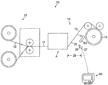
Fig. 1 is a schematic diagram of a production line.
Fig. IA is a more detailed schematic diagram of area A of Fig. 1.
Fig. 1 B is a top view of a laminate as it passes through area A.
Fig.-2-is a- photograph of a-surface of-a-laminate--after penetration of a
colorant-containing
liquid.
DETAILED DESCRIPTION
Referring to Fig. 1, a production line 10 includes a lamination area 12, and a
testing area
14. A long web of a laminate 11 is formed from layers of sheet material in
lamination area 12,
the layers of sheet material including at least one layer 13 configured to
provide barrier
4
CA 02413765 2010-05-14
63266-69
properties to the laminate. Laminate 11 may include, for example, (a) a layer
of fabric, e.g.,
tricot, and/or nonwoven, (b) a layer of foam and/or a breathable film, and (c)
a layer of a barrier
film. The laminate may be formed by any suitable process, e.g., flame
lamination, adhesive, or
applying heat and pressure at.a nip. Adhesive may be applied, for example, as
a hot nielt or by
solvent coating. Suitable adhesives include urethanes, olefins, polyesters,
polyamides, PVC,
PVDC, nitrocellulose and butyrates. Laminate I I may be used in a wide variety
of applications,
including waterproof breathable laminates, breathable chemical protection
laminates, viral
protection laminates, and allergy proof and fluid proof laminates.
The laminate 1 I then travels to testing area 14, where it is tested for the
effectiveness of
its barrier properties, i.e., tested for the presence of small holes such as
pinholes, as the laminate
is moving along the production line and passes through the testing area 14. As
it exits testing
area 14, the laminate is wound up on a take-up roll 15. If desired, the
laminate may be subjected
to further inspection, testing or processing before or after it is wound up on
take-up roll 15. The
laminate may be drawn through the production line at relatively low speeds,
e.g., 10 ft/min, or
relatively high speeds, e.g., up to 400 ft/min or more.
Referring to Fig. I A, an applicator 16, is configured to apply a
volume of liquid 17 to surface 18 of the laminate 11. Suitable applicators
include spray nozzle
systems, for example spray nozzles 21 as shown in Figs. IA and 1B. Other
suitable applicators
include roll coating systems and felt applicators (not shown). Suitable
liquids generally have
low viscosity and low surface tension. Suitable liquids include water;
alcohols, e.g., methyl,
ethyl, or isopropyl alcohol; alcohol/water solutions; and other hydrocarbon
solvents, e.g.,
acetates, alone or in solution with water. Surfactants may be added, to reduce
surface tension,
provided the surfactant does not have a deleterious effect on the laminate.
The liquid may
include a colorant, e.g., a dye, for reasons that will be described below. One
specific example of
a liquid that is useful when testing for pinholes in a flame-laminated
laminate made of polyester
fabric, a urethane foam core, and a thermoplastic urethane barrier film
consists of 30-70%
isopropyl alcohol in water, colored with food coloring.
As shown in Fig. IB, the liquid 17 is applied in a continuous film 19 that
substantially
spans the full width W of the laminate (the cross-machine dimension). Any
desired volume of
liquid may be applied, as long as the width of the laminate that needs to be
tested is covered. By
substantially spans we mean that the film 19 covers as much of the width as
will be used in a
5
CA 02413765 2002-12-10
finished product, typically within a margin of 1-2 inches of each longitudinal
edge 31 of the
laminate. The 1-2 inch margin (e.g., margin 23 in Fig. 1B) would generally be
discarded and
therefore need not be tested. These liquid-free margins 23 along the edges 31
of the laminate can
be provided,-for example, by applying the liquid 17 from a number of closely
spaced nozzles 21,
and turning off the nozzles that are adjacent the edges of the laminate
(nozzles 21A and 21B in
Fig. 1B). If desired, the entire width of the laminate may be covered with
liquid. In this case; it
may be desirable to provide a barrier to prevent liquid from flowing over the
edges of the
laminate.
As shown in Fig. I A, testing area 14 also includes a vacuum source 20,
positioned below
the applicator 16. The vacuum source may be positioned immediately below the
applicator 16,
as shown, or downstream of the, applicator by a distance that allows time for
the applied liquid to
thoroughly coat the upper surface of the laminate, e.g., an inch or less-
downstream. The vacuum
source faces the opposite surface 22 of the laminate from below. Vacuum source
20 is in
communication with a vacuum device that is configured to apply to the laminate
a pressure -
differential between the two surfaces 18, 22. Suitable vacuum devices include
a vacuum bar,
conveyor or table perforated with a hole pattern, a vacuum slot, or a rotary
vacuum roll. The
vacuum device should generally be configured so as not to damage the surface
22 of the
laminate.
The pressure differential may be at least as large as the maximum pressure
differential
that is expected to occur between the two surfaces during subsequent
processing and use. This
will simulate use conditions, and allow detection of pinholes of a size that
will cause leakage
during expected use conditions. Preferably, the pressure differential is at
least 15% larger, more
preferably at least 20% larger than the maximum expected pressure
differential.
The pressure differential applied to the laminate overcomes the surface
tension of the
liquid which would otherwise tend to prevent it from entering the pin holes
(e.g., by capillary,
action) and being drawn to the lower surface of the laminate. If'there are any
small-holes in the
laminate the pressure differential causes the liquid to be drawn through the
small holes to surface
22. When the liquid reaches surface 22 it will tend to stain the surface in
the vicinity of the
holes. Figure 2 shows a photograph of the stained surface after the liquid has
been drawn
through the small holes 25. If the liquid contains a colorant, the colored
liquid will stain the
surface 22 in a way that is even more apparent than without the colorant.
6
CA 02413765 2002-12-10
Suitable pressure differentials will depend on the maximum expected pressure
differential
for a particular application, but are generally in the range of 10 to 50
inches of water, typically
15 to 30 inches of water. Higher pressure differentials may allow the laminate
to be passed more
quickly through testing area 14. Higher pressure differentials also may allow
higher surface
tension liquids to be used, if desired.
As shown in Fig. 1, at a location 27 that is sufficiently downstream from the
vacuum port
to give time for the liquid to be drawn through the small holes to the bottom
surface is an
inspection station 26. The distance 29 between the location of the vacuum port
and the location
of the inspection station may be very small, for example an inch or less, but
for convenience may
be 6 feet or more. At inspection station 26, the surface 22 of the laminate is
inspected to detect
liquid that has passed from surface 18 through to surface 22. Inspection may
be performed by a
machine vision system or other automated inspection system, or by human visual
inspection.
Suitable machine vision systems are commercially available, e.g., from Elba,
and Cognex
Systems. If a colorant is used, the surface 22 may be inspected for staining.
If no colorant is
used, the surface 22 may be visually inspected for wetness, or may be
otherwise tested for
surface moisture.
The presence of pinholes may indicate that the barrier film that is being fed
to the
lamination area 12 should be inspected and tested for pinholes. It may be
possible to make these
adjustments without stopping the process, or it may be necessary to bring the
production line
down until the problem is corrected. When production begins again, the
operator. can easily
determine whether the problem has been successfully been corrected based on
the results at
inspection station 26.
If staining or moisture is detected, an alarm may be triggered by the machine
vision
system, and/or a flag 61 (Fig. IB) may be placed on an edge of the laminate
near the location of
the staining/moisture. The flag may be applied at a marking station 63. To
preserve the
continuity of the process, the portion of the laminate containing the hole(s)
will generally be
wound up on the take-up roll 15, and the portion removed and discarded during
subsequent
manufacturing steps. When more that a few pinholes are detected, this may
indicate to the
operator of the machine that the process parameters should be adjusted to
address the problem
causing the holes.
7
CA 02413765 2002-12-10
The machine vision system can be arranged to display to the operator on a
monitor 65
information about the number of pinholes that have been detected in. a
particular recent section of
the laminate web, or statistical information about the history of pinholes
over a longer section of
the web. The statistical information could indicate one or more portions of
the web, in a cross-
wise direction, that have experienced more or less than average pinholes, or
the variations of
patterns of pinholes along the length of the web. The machine vision system
might also be
arranged to display to the user images of portions of the laminate or maps
that represent the
surface of the laminate and show the actual locations of pinholes or the
average locations of
pinholes in the laminate. These features allow the operator to immediately
observe if a process
parameter is moving out of control, based on the number of pinholes being
detected by the vision
system. As a result, corrective action. can be taken immediately, minimizing
the amount of
defective laminate that is produced.
The machine vision system also frees the operator from standing continually at
an
inspection station. The machine vision system can be configured to provide an
audible alarm
and/or a visual indicator (e.g., a flashing light) when pinholes are detected,
so that the operator
may step away from the monitor 65 and still be notified when pinholes occur.
Moreover, the
machine vision system can be configured to store pinhole data and images of
the web .surface.
Thus, if the operator does not see a pinhole before the laminate is rolled
onto the take-up roll, the
operator can later pull up a picture of the pinhole on the monitor, and print
the picture if desired.
Additionally, the machine vision system can be configured to document the
number and
location of pinholes over an entire run of material, allowing the manufacturer
to provide a quality
record to a purchaser of the, laminate. The machine vision system can also be
configured to track
the number of pinholes by shift, by operator, by product type and by process
condition. This
information can be used to develop a better understanding of the lamination
process and to
optimize the process, allowing pinholes to be more easily, avoided and
corrected and improving
product quality.
As shown in Fig. IA, if desired, the production line may also include a
scraper 30,
configured to remove excess liquid 17 from surface 18 of the web after the
vacuum has been
applied. If a colorant is used in the liquid 17, the production line may also
include a rinse station
32, where a rinsing liquid 34 is applied from nozzles 33 to surface 18 to
remove or reduce the
staining produced by the colored liquid.
8
CA 02413765 2002-12-10
Other embodiments are within the scope of the following claims.
For example, while the invention has been described above in the context of
laminates,
the methods described are also suitable for use in testing other types of
webs, e.g., barrier films
that are not laminated to other layers. In some cases, it may be desirable to
cover the rotary
vacuum described above with a thin layer of foam to prevent damage to the film
and enhance
wetting of the inspection surface of the film with any fluid that passes
through the film. If a
colorant is included, the colorant may be selected to effectively wet the
inspection surface of the
film.
Additionally, while in the implementation described above inspection takes
place online,
in some applications the inspection station may be omitted. Inspection can be
performed in a
later, post-production step, or omitted entirely. For example, the finished
laminate may be
shipped to a customer without inspection, and the customer may inspect the
inspection surface
for staining. The customer may then remove any stained areas (areas with
holes) if desired.
9