Note: Descriptions are shown in the official language in which they were submitted.
CA 02413794 2002-12-18
WO 01/98632 PCT/US01/19020
INDUCTIVELY COUPLED METHOD AND APPARATUS OF
COMMUNICATING WITH WELLBORE EQUIPMENT
BACKGROUND
The invention relates to an inductively coupled method and apparatus of
communicating with wellbore equipment.
A major goal in the operation of a well is improved productivity of the well.
The
production of well fluids may be affected by various downhole conditions, such
as the
presence of water, pressure and temperature conditions, fluid flow rates,
formation and
fluid properties, and other conditions. Various monitoring devices may be
placed
downhole to measure or sense for these conditions. In addition, control
devices, such as
flow control devices, may be used to regulate or control the well. For
example, flow
control devices can regulate fluid flow into or out of a reservoir. The
monitoring and
control devices may be part of an intelligent completion system (ICS) or a
permanent
monitoring system (PMS), in which communications can occur between downhole
devices and a well surface controller. The downhole devices that are part of
such systems
are placed in the well during the completion phase with the expectation that
they will
remain functional for a relatively long period of time (e.g., many years).
To retrieve information gathered by downhole monitoring devices and/or to
control activation of downhole control devices, electrical power and signals
may be
communicated down electrical cables from the surface. However, in some
locations of
the well, it may be difficult to reliably connect electrical conductors to
devices due to the
presence of water and other well fluids. One such location is in a lateral
branch of a
multilateral well. Typically, completion equipment in a lateral branch is
installed
separately from the equipment in the main bore. Thus, any electrical
connection that
needs to be made to the equipment in the lateral branch would be a "wet"
connection due
to the presence of water and other liquids.
1
.. . t._..... , ... . .. . . .
CA 02413794 2006-05-08
78543-112
In addition, because of the presence of certain completion components, making
an
electrical connection may be difficult and impractical. Furthernaore, the
hydraulic
integrity of portions of the well may be endangered by such connections. One
example
involves sensors, such as resistivity electrodes, that are placed outside the
casing to
measure the resistivity profile of the surrounding formation. Electrical
cables are
typically run within the casing, and mal:ing an electrical connection through
the casing is
undesirable. Resistivity electrodes may be used to monitor for the presence of
water
behind a hydrocarbon-bearing reservoir. As the hydrocarbons are produced, the
water
may start advancing toward the wellbore. At some point, water may be produced
into the
wellbore. Resistivity electrodes provide measurements that allow a well
operator ta
determine when water is about to be produced so that corrective action may be
taken.
However, without the availabiIity of cost effective and reliable mechanisms to
communicate electrical power and signaling with downhole monitoring and
control
devices, the use of such devices to improve the productivity of a well may be
ineffective.
Thus, a need exists for an improved method and apparatus for communicating
electrical
power and/or signaling with downhole modules.
SUMMARY
In general, according to one embodiment, an apparatus for use in a wellbore
portion having a liner includes an electrical device attached outside the
liner and
electrically connected to the electrical device. A second inductive coupler
portion is
positioned inside the liner to communicate an electrical signaling with the
first inductive
coupler portion.
In general, according to another embodiment, an apparatus for use in a well
having a main bore and a lateral branch having an electrical device includes
an inductive
coupler mechanism to electricaIly communicate electrical signaling in the main
bore with
the electrical device in the lateral branch.
2
. . .... ~ .. . , . .... ... .
CA 02413794 2006-05-08
78543-112
According to another embodiment of the present
invention, there is provided an apparatus for use in a
wellbore, comprising: a liner section having a wall; an
electrical device for positioning outside the liner section
in an annular region defined by an outer surface of the
liner section and the welibore; a first inductive coupler
portion provided in a cavity in the wall of the liner
section and electrically connected to the electrical device;
and a second inductive coupler portion positioned inside the
liner section to communicate electrical signaling with the
first inductive coupler portion.
According to still another embodiment of the
present invention, there is provided a module for use in a
wellbore having liner sections, comprising: a housing having
a first end adapted to be connected to a first liner
section, and a second end adapted to be connected to a
second liner section; an electrical device mounted outside
the housing for positioning in an annular region between an
outer surface of the housing and wellbore; and an inductive
coupler portion attached to the housing and electrically
coupled to the electrical device.
According to yet another embodiment of the present
invention, there is provided a method of communicating with
an electrical device in a wellbore, having a liner section,
the liner section having a wall, the method comprising:
providing an inductive coupler mechanism, the inductive
coupler mechanism comprising a first part inside the liner
section and a second part provided in a cavity of the wall
of the liner section and electrically connected to the
electrical device that is mounted outside the liner section
2a
4... . .. . .. .. . . .
CA 02413794 2006-05-08
78543-112
in an annular region defined by an outer surface of the
liner section and the wellbore; and communicating electrical
signaling between the first and second parts of the
inductive coupler mechanism to communicate with the
electrical device.
According to a further embodiment of the present
invention, there is provided a completion string for use in
a wellbore, comprising: a casing section; a production
tubing section; a first inductive coupler portion attached
to the production tubing section; an electrical device for
positioning outside the casing section in an annular region
defined between the casing section and the wellbore; and a
second inductive coupler portion electrically connected to
the electrical device and provided in a cavity in the casing
section and positioned in the proximity of the first
inductive coupler portion.
According to yet a further embodiment of the
present invention, there is provided a completion string for
use in a well having a main bore and lateral branches,
comprising: equipment in the main bore and in at least first
and second lateral branches; a first inductive coupler
assembly proximal the equipment in the main bore; a second
inductive coupler assembly proximal the equipment in the
first lateral branch; an electrical cable connecting the
first and second inductive coupler assemblies; and a third
inductive coupler assembly proximal the equipment in the
second lateral branch.
According to still a further embodiment of the
present invention, there is provided a completion string for
use in a wellbore, comprising: a liner having an inner bore;
2b
_;.
CA 02413794 2006-05-08
78543-112
and a liner module connected to the liner and comprising: a
housing defining an inner bore having a diameter that is
substantially the same as or greater than the inner bore of
the liner, one or more electrical devices positioned outside
the housing in an annular region between the housing and the
wellbore, and an inductive coupler portion provided in a
casing of the housing and electrically connected to the one
or more electrical devices.
Other features and embodiments will become
apparent from the following description, the drawings, and
the claims.
2c
CA 02413794 2002-12-18
WO 01/98632 PCT/US01/19020
BRIEF DESCRIPTION OF THE DRAWINGS
Fig. 1A illustrates an embodiment of a completion string including electrical
devices and an inductive coupler assembly to communicate electrical power and
signaling to the electrical devices.
Fig. 1B illustrates an example of a control module that is part of the
electrical
devices of Fig. 1A.
Fig. 2A is a cross-sectional view of a casing coupling module connected to
casing
sections in the completion string of Fig. 1A, the casing coupling module
including a first
portion of the inductive coupler assembly, sensors, and a control module in
accordance
with an embodiment.
Fig. 2B illustrates a portion of a casing coupling module in accordance with
another embodiment.
Fig. 3 is a cross-sectional view of a landing adapter in accordance with an
embodiment including landing and orientation keys to engage profiles in the
casing
coupling module of Fig. 2, the landing adapter further comprising a second
portion of the
inductive coupler assembly to electrically communicate with the first
inductive coupler
portion of the casing coupling module.
Fig. 4 is an assembled view of the landing adapter of Fig. 3 and the casing
coupling module of Fig. 2 in accordance with one embodiment.
Fig. 5 illustrates an inductive coupler assembly in accordance with another
embodiment to communicate electrical power and signaling to electrical devices
placed
outside a liner section.
Fig. 6 illustrates an embodiment of an inductive coupler assembly.
Fig. 7 is a sectional view showing an embodiment of completion equipment for
use in a well having a main bore and at least one lateral branch.
Fig. 8 is a perspective view in partial section of a lateral branch template
in
accordance with an embodiment having an upper portion cut away to show
positioning of
a diverter member within the upper portion of the template.
3.
CA 02413794 2002-12-18
WO 01/98632 PCT/US01/19020
Fig. 9 is a perspective view similar to that of Fig. 8 and further showing a
liner
connector member and isolation packers in assembly with the lateral branch
template.
Fig. 10 is a perspective view of the liner connector member of Fig. 9.
Fig. 11 is a perspective view showing the diverter member of Fig. 8 or 9.
Fig. 12 is a fragmentary sectional view showing part of the completion
equipment
of Fig. 7 including a main casing in a main bore, the lateral branch template
of Fig. 8, a
casing coupling module, a lateral branch liner diverted through a window in
the main
casing, and inductive coupler portions in accordance with an embodiment.
Fig. 13 is a fragmentary sectional view of the components shown in Fig. 12 and
in
addition a portion of a production tubing in the main bore and a control
and/or
monitoring module in the lateral branch, each of the production tubing and
control and/or
monitoring module including an inductive coupler portion to communicate
electrical
power and signaling.
Fig. 14 illustrates completion equipment for communicating electrical power
and
signaling to devices in lateral branches of a multilateral well.
Fig. 15 is a fragmentary sectional view of the components shown in Fig. 13 in
a
different phase.
DETAILED DESCRIPTION
In the following description, numerous details are set forth to provide an
understanding of the present invention. However, it will be understood by
those skilled
in the art that the present invention may be practiced without these details
and that
numerous variations or modifications from the described embodiments may be
possible.
As used here, the terms "up" and "down"; "upper" and "lower"; "upwardly" and
downwardly"; and other like terms indicating relative positions above or below
a given
point or element are used in this description to more clearly described some
embodiments
of the invention. However, when applied to equipment and methods for use in
wells that
are deviated or horizontal, such terms may refer to a left to right, right to
left, or other
relationship as appropriate.
4
CA 02413794 2002-12-18
WO 01/98632 PCT/US01/19020
In accordance with some embodiments, inductive couplers are used to
communicate electrical power and signaling to devices in a wellbore. Such
devices may
include monitoring devices, such as sensors, placed outside casing or another
type of
liner to measure the resistivity or other characteristic of the surrounding
formation: Other
types of monitoring devices include pressure and temperature sensors, sensors
to detect
stress experienced by completion components (such as strain gauges), and other
monitoring devices to monitor for other types of seismic, environmental,
mechanical,
electrical, chemical, and any other conditions. Stress recorders may also be
located at a
junction between a main wellbore and a lateral branch. Such stress recorders
are used to
monitor the stress of a junction that is predeformed and expanded by a
hydraulic jack
once positioned downhole. The stress due to the expansion operation is
monitored to
ensure structural integrity can be maintained. Electrical power and signaling
may also be
communicated to control devices that control various components, such as
valves,
monitoring devices, and so forth. By using inductive couplers, wired
connections can be
avoided to certain downhole monitoring and/or control devices. Such wired
connections
may be undesirable due to presence of well fluids and/or downhole components.
In accordance with some embodiments, electrical devices and a portion of an
inductive coupler may be assembled as part of a completion string module, such
as a
section of casing, liner, or other completion equipment. This provides a more
modular
implementation to facilitate the installation of monitoring and/or control
devices in a
wellbore.
In accordance with a further embodiment, inductive couplers may be used to
couple electrical power and signaling between components in a main bore and
components in a lateral branch of a multilateral well. In one arrangement,
inductive
couplers may be assembled as part of a connector mechanism used to connect
lateral
branch equipment to main bore equipment.
Referring to Fig. 1A, a completion string according to one embodiment is
positioned in a well, which may be a vertical, horizontal, or deviated
welibore, or a
multilateral well. The completion string includes casing 12 lining a wellbore
10 and
5
CA 02413794 2006-05-08
78543-112
production tubing 14 placed inside the casing 12 that extends to a formation
16
containing hydrocarbons. A packer 18 may be used to isolate the casing-tubing
annulus
15 from the portion of the wellbore below the packer 18. Although reference is
made to
casing in this discussion, other embodiments may include other types of liners
that may
be employed in a wellbore section. A liner may also include a tubing that is
expandable
to be used as a liner.
One or more flow control devices 20, 22, and 24 may be attached to the
production,tubing 14 to control fluid flow into the production tubing 14 from
respective
zones in the formation 16. The several zones are separated by packers 18, 26,
and 28.
The flow control devices 20,22, and 24 may be independently activated. Each
flow
control device may include any one of various types of valves, including
sliding sleeve
valves, disk valves, and other types of valves. Exaniples of disk valves are
described in
U.S. Patent No. 6,328,112, entitled "Valves for Use in Wells", filed February
1, 1999; and
U.S. Patent No. 6,227,302, entitled "Apparatus and Method for Controlling
Fluid Flow in
1:5 a Wellbore", filed June 3, 1999, both having common assignee as the
present application.
Each flow control device 20, 22, or 24 may be an on/off device (that is,
actuatable
between open or closed positions). In further embodiments, each flow control
device
may also be actuatable to at least an intermediate position between the open
and closed
positions. An intermediate position refers to a partially open position that
may be set at
some percentage of the fully open position. As used here, a "closed" position
does not
necessarily mean that all fluid flow is blocked. There may be some leakage,
with a flow
of about 6% or less of a fully open flow rate being acceptable in some
applications.
During production, the illustrated flow control devices 20, 22, and 24 may be
in
the open position or some intermediate position to control production fluid
flow from
respective zones into the production tubing 14. However, under certain
conditions, fluid
flow through the flow control devices 20, 22, and 24 may need to be reduced or
shut off.
One example is when one zone starts producing water. In that case, the flow
control
6
CA 02413794 2002-12-18
WO 01/98632 PCT/US01/19020
device associated with the water-producing zone may be closed to prevent
production of
water.
One problem that may be encountered in a formation is the presence of a layer
of
water (e.g., water layer 30) behind a reservoir of hydrocarbons. As
hydrocarbons are
produced, the water level may start advancing towards the wellbore. One zone
may start
producing water earlier than another zone. To monitor for the advancing layer
of water
30, sensors 32 (e.g., resistivity electrodes) may be used. As illustrated, the
resistivity
electrodes 32 may be arranged along a length of a portion of the casing 12 to
monitor the
resistivity-profile of the surrounding formation 16. As the water layer
advances, the
resistivity profile may change. At some point before water actually is
produced with
hydrocarbons, one or more of the flow control devices 20, 22, and 24 may be
closed. The
remaining flow control devices may remain open to allow continued production
of
hydrocarbons.
Typically, the resistivity electrodes 32 are placed outside a section of the
casing
12 or some other type of liner. As used here, a "casing section" or "liner
section" may
refer to an integral segment of a casing or liner or to separate piece
attached to the casing
or liner. The casing or liner section has an inner surface (defining a bore in
which
completion equipment may be placed) and an outer surface (typically cemented
or
otherwise affixed to the wall of the wellbore). Devices mounted on, or
positioned,
outside of the casing or liner section are attached, either directly or
indirectly, to the outer
surface of the casing or liner section. Devices are also said to be mounted on
or
positioned outside the casing or liner section if they are mounted or
positioned in a
cavity, chamber, or conduit defined in the housing of the casing or liner
section. A
device positioned inside the casing or liner section is placed within the
inner surface of
the casing or liner section.
In the illustrated embodiment of Fig. 1A, the electrodes 32 may be coupled to
a
sensor control module 46 by an electrical line 48. The sensor control module
46 may be
in the form of a circuit board having control and storage units (e.g.,
integrated circuit
devices). Forming a wired connection from an electrical cable inside the
casing section
7
CA 02413794 2002-12-18
WO 01/98632 PCT/US01/19020
to the electrodes 32 and control module 46 outside the casing section may be
difficult,
impractical, and unreliable. In accordance with some embodiments, to provide
electrical
power and to communicate signaling to the electrodes 32 and the control module
46, an
inductive coupler assembly 40 is used. The inductive coupler assembly 40
includes an
inner portion attached to a section of the production tubing 14 or other
completion
component and an outer portion 44 attached to the casing section. The outer
inductive
coupler portion 44 may be coupled by an electrical link 45 to the control
module 46. The
inner inductive coupler portion 42 is connected to an electrical cable 50,
which may
exiend to a power source and surface controller 17 located at the well surface
or to a
power source and controller 19 located somewhere in the wellbore 10. For
example, in
an intelligent completion system (ICS), power sources and controllers may be
included in
downhole modules. The controllers 17 and 19 may each provide a power and
telemetry
source.
The electrical cable 50 may also be connected to the flow control devices 20,
22,
and 24 to control actuation of those devices. The electrical cable 50 may
extend through
a conduit in the housing of the production tubing 14, or the cable 50 may run
outside the
tubing 14 in the casing-tubing annulus. In the latter case, the cable 50 may
be routed
through packer devices, such as packer devices 18, 26, and 28.
Some type of addressing scheme may be used to selectively access one or more
of
the flow control devices 20, 22, and 24 and the sensor control module 46
coupled to the
electrodes 32. Each of the components downhole may be assigned a unique
address such
that only selected one or ones of the components, including the flow control
devices 20,
22, and 24 and the sensor module 46, are activated.
To activate the sensor control module 46, power and appropriate signals are
sent
down the cable 50 to the inner inductive coupler portion 42. The power and
signals are
inductively coupled from the inner inductive coupler portion 42 to the outer
inductive
coupler portion 44. Referring to Fig. IB, the outer inductive coupler portion
44
communicates the electrical power to the control module 46, which includes a
first
interface 300 coupled to the link 45 to the inductive coupler portion 44. A
power supply
8
CA 02413794 2002-12-18
WO 01/98632 PCT/US01/19020
302 may also be included in the control module 46. The power supply 302 may
include a
local battery or it may be powered by electrical energy communicated to the
outer
inductive coupler portion 44. A control unit 304 in the control module 46 is
capable of
decoding signals received by the inductive coupler portion 44 to activate an
interface 308
coupled to the link 48 to the electrodes 32. The control unit 304 may include
a
microcontroller, microprocessor, programmable array logic, or other
programmable
device. The measured signals from the electrodes 32 are received by the sensor
control
module 46 and communicated to the outer inductive coupler portion 44. The
received
data is coupled from the outer inductive coupler portion 44 to the inner
inductive coupler
portion 42, which in turn communicates the signals up the electrical cable 50
to the
surface controller 17 or to the downhole controller 19. The resistivity
measurements
made by the electrodes 32 are then processed either by the surface controller
17 or
downhole controller 19 to determine if conditions in the formation are such
that one or
more of the flow control devices 20, 22, and 24 need to be shut off.
The sensor control module 46, provided that it has some form of power (either
in
the form of a local battery or power inductively coupled through the inductive
coupler
assembly 40) may also periodically (e.g., once a day, once a week, etc.)
activate the
electrodes 32 to make measurements and store those measurements in a local
storage unit
306, such as a non-volatile memory (EPROM, EEPROM, or flash memory) or a
memory
such as a dynamic random access memory (DRAM) or static random access memory
(SRAM). In a subsequent access of the sensor control module 46 over the
electrical cable
50, the contents of the storage unit 306 may be communicated through the
inductive
coupler assembly 40 to the electrical cable 50 for communication to the
surface controller
17 or downhole controller 19.
In one embodiment, power to the control module 46 and electrodes 32 may be
provided by a capacitor 303 in the power supply 302 that is trickle-charged
through the
inductive coupler assembly 40. Electrical energy in the electrical cable 50
may be used
to charge the capacitor 302 over some extended period of time. The charge in
the
capacitor 302 may then be used by the control unit 304 to activate the
electrodes 32 to
9
CA 02413794 2002-12-18
WO 01/98632 PCT/US01/19020
make measurements. If the coupling efficiency of the inductive coupler
assembly 40 is
relatively poor, then such a trickle-charge technique may be effective in
generating the
power needed to activate the electrodes 32.
Referring to Fig. 2A, a casing coupling module 100 is illustrated. The casing
coupling module 100 is adapted to be attached to the well casing 12, such as
by threaded
connections. The sensor control module 46 and electrodes 32 may be mounted on
the
outer wall 106 of (or alternatively, to a recess in) the casing module housing
105. A
protective sleeve 107 may be attached to the outer wall of the casing coupling
module
100 to protect the control module 46 and electrodes 32 from damage when the
casing
coupling module 100 is run into the wellbore. In an alternative arrangement,
the control
module 46 and/or the electrodes 32 may be mounted to the inner wall 109 of the
protective sleeve 107. If the electrodes 32 are resistivity electrodes, then
the sleeve 107
may be formed of a non-conductive material. With other types of electrodes,
conductive
materials such as steel may be used. In yet further embodiments, as shown in
Fig. 2B,
instead of a sleeve, a layer of coating 111 may be formed around the devices
32 and 46.
The outer inductive coupler portion 44 may be mounted in a cavity of the
housing
105 of the casing coupling module 100. Effectively, the casing coupling module
100 is a
casing section that includes electrical control andlor monitoring devices. The
casing
coupling module 100 provides for convenient installation of the inductive
coupler portion
44, control module 46, and electrodes 32. The module 100 may also be referred
to as a
liner coupling module if used with other types of liners, such as those found
in lateral
branch bores and other sections of a well. The inner diameter of the casing or
liner
coupling module 100 may be substantially the same as or greater than the inner
diameter
of the casing or liner to which it is attached. In further embodiments, the
casing or liner
coupling module 100 may have a smaller inner diameter.
A landing profile 108 is provided in the inner wall 110 of the housing 105 of
the
casing coupling module 100. The landing profile 108 is adapted to engage a
corresponding member in completion equipment adapted to be positioned in the
casing
coupling module 100. One example of such completion equipment is a section of
the
CA 02413794 2002-12-18
WO 01/98632 PCT/US01/19020
production tubing 14 to which the inner inductive coupler portion 42 is
attached. The
section of the tubing 14 (or of some other completion equipment) that is
adapted to be
engaged in the casing coupling module 100 may be referred to as a landing
adapter.
The casing coupling module 100 further includes an orienting ramp 104 and an
orientation profile 102 to orient the landing adapter inside the casing
coupling module
100. Landing and orientation keys on the landing adapter are engaged to the
landing
profile 108 and orientation profile 102, respectively, of the casing coupling
module.
In other embodiments, other types of orienting and locator mechanisms may be
employed. For example, another type of locator mechanism may include an
inductive
coupler assembly. An inductive coupler portion having a predetermined
signature (e.g.,
generated output signal having predetermined frequency) may be employed. When
completion equipment are Iowered into the wellbore into the proximity of the
locator
mechanism, the predetermined signature is received and the correct location
can be
determined. Such a locator mechanism avoids the need for mechanical profiles
that may
cause downhole devices to get stuck.
Referring to Fig. 3, a landing adapter 200 for engaging the inside of the
casing
coupling module 100 of Fig. 2 is illustrated. The landing adapter 200 includes
landing
keys 202 and an orientation key 204. The inner inductive coupler portion 42
may be
mounted in a cavity of the housing 206 of the landing adapter 200 electrically
connected
to driver circuitry 208 to electrically communicate with one or more
electrical lines 210
in the landing adapter 200. Although shown as extending inside the inner bore
212 of the
landing adapter 200, an alternative embodiment may have the one or more
electrical lines
210 extending through conduits formed in the housing 206 or outside the
housing 206.
The one or more electrical lines 210 are connected to electronic circuitry 216
attached to
the landing adapter 200. The electronic circuitry 216 may in turn be connected
to the
electrical cable 50 (Fig. 1).
Referring to Fig. 4, the landing adapter 200 is shown positioned and engaged
inside the casing coupling module 100. The orienting ramp 104 and orienting
profile 102
of the casing coupling member 100 and the orienting key 204 of the landing
adapter 200
11
CA 02413794 2002-12-18
WO 01/98632 PCT/US01/19020
are adapted to orient the adapter 200 to a desired azimuthal relationship
inside the casing
coupling module 100. In another embodiment, the orienting mechanisms in the
landing
adapter 200 and the casing coupling module 100 may be omitted. In the engaged
position, the inner inductive coupler portion 42 attached to the landing
adapter 200 and
the outer inductive coupler portion 44 attached to the casing coupling module
100 are in
close proximity so that electrical power and signaling may be inductively
coupled
between the inductive coupler portions 42 and 44.
In operation, a lower part of the casing 12 (Fig. 2) may first be installed in
the
wellbore 10. Following installation of the lower casing portion, the casing
coupling
module 100 may be lowered and connected to the lower casing portion. Next, the
remaining portions of the casing 12 may be installed in the wellbore 10.
Following
installation of the casing 12, the rest of the completion string may be
installed, including
the production tubing, packers, flow control devices, pipes, anchors, and so
forth. The
production tubing 14 is run into the wellbore 10 with the integrally or
separately attached
landing adapter 200 at a predetermined location along the tubing 14. When the
landing
adapter 200 is engaged in the casing coupling module 100, electrical power and
signaling
may be communicated down the cable 50 to activate the sensor control module 46
and
electrodes 32 to collect resistivity information.
In further embodiments, other inductive coupler assemblies similar to the
inductive coupler assembly 40 may be used to communicate electrical power and
signaling to other control and monitoring devices located elsewhere in the
well.
Referring to Fig. 6, the inductive coupler assembly 40 according to one
embodiment is shown in greater detail. The inner inductive coupler portion 42
includes
an inner coi152 that surrounds an inner core 50. The outer inductive coupler
portion 44
includes an outer core 50 that encloses an outer coil 56. According to one
embodiment,
the cores 50 and 54 may be formed of any material that has a magnetic
permeability
greater than that of air and an electrical resistivity greater than that of
solid iron. One
such material may be a ferrite material including ceramic magnetic materials
formed of
ionic crystals and having the general chemical composition MeFe203, where Me
is
12
CA 02413794 2006-05-08
78543-112
selected from the group consisting of manganese, nickel, zinc, magnesium,
cadmium,
cobalt, and copper. Other materials forming the core may be iron-based
magnetic alloy
materials that have the required magnetic permeability greater than that of
air and that
have been formed to create a core that exhibits the electrical resistivity
greater than that
of solid iron.
The inner coil 52 may include a multi-turn winding of a suitable conductor or
insulated wire wound in one or more layers of uniform diameter around the mid-
portion
of the core 50. A tubular shield 58 formed of a non-magnetic material may be
disposed
around the inner inductive coupler portion 42. The material used for the
shield 58 may
include an electrically-conductive metal such as aluminum, stainless steel, or
brass
arranged in a fashion as to not short circuit the inductive coupling between
inductive
coupler portions 42 and 44. The outer coil 56 similarly includes a multi-turn
winding of
an insulated conductor or wire arranged in one or more layers of uniform
diameter inside
of the tubular core 54. Although electrical insulation is not required, the
outer inductive
coupler portion 44 may be secured to the casing housing 105 by some
electrically
insulating mechanism, such as a non-conductive potting compound. A protective
sleeve
60 may be used to protect the outer inductive coupler portion 44. The
protective sleeve
60 may be formed of a non-magnetic material similar to the shield 58.
Further description of some embodiments of the inductive coupler portions 42
and
44 may be found in U.S. Patent No. 4,901,069, entitled "Apparatus for
Electromagnetically Coupling Power and Data Signals Between a First Unit and a
Second
Unit and in Particular Between Well Bore Apparatus and the Surface," issued
Febraary
13, 1990; and U.S. Patent No. 4,806,928, entitled "Apparatus for
Electromagnetically
coupling Power and Data Signals Between Well Bore Apparatus and the Surface,"
issued
February 21, 1989, both having common assignee as the present application.
To couple electrical energy between the inductive coupler portions 42 and 44,
an
electrical current (alteinating current or AC) may be placed on the windin;s
of one of the.
two coils 52 and 56 (the primary coil), which generates a magnetic field that
is coupled to
13
CA 02413794 2002-12-18
WO 01/98632 PCT/US01/19020
the other coil (the secondary coil). The magnetic field is converted to an AC
current that
flows out of the secondary coil. The advantage of the inductive coupling is
that there is
no requirement for a conductive path from the primary to secondary coil. For
enhanced
efficiency, it may be desirable that the medium between the two coils 52 and
56 have
good magnetic properties. However, the inductive coupler assembly 40 is
capable of
transmitting power and signals across any medium (e.g., air, vacuum, fluid)
with reduced
efficiency. The amount of power and data rate that can be transmitted by the
inductive
coupler assembly 40 may be limited, but the typically long data collection
periods of the
downhole application permits a relatively low rate of power consumption and
requires a
relatively low data rate.
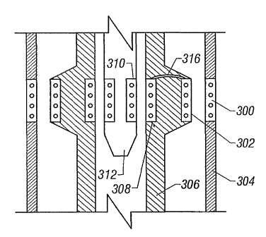
Referring to Fig. 5, according to another embodiment, multiple layers may be
present between the outer-most inductive coupler portion and the inner-most
inductive
coupler portion. As shown in Fig. 5, the outer-most inductive coupler portion
300 may
be located outside or part of a casing or liner 304. A section of a tubing or
pipe 306 (e.g.,
production tubing) may include a first inductive coupler portion 302 adapted
to cooperate
with the inductive coupler portion 300. A second inductive coupler portion 308
may also
be integrated into the inner diameter of the tubing or pipe 306 for coupling
to an inner-
most inductive coupler portion 310 that may be located in a tool 312 located
in the bore
of the tubing or pipe 306. The tool 312 may be, for example, a diagnostic tool
that is
lowered on a wireline, slickline, or tubing into the well for periodic
monitoring of certain
sections of the well. The inductive coupler portions 302 and 308 in the
housing of the
tubing 306 may be electrically connected by conductor(s) 316. The multi-
layered
inductive coupler mechanism may also be employed to communicate with other
downhole devices.
A method and apparatus has been defined that allows communications of
electrical power and signaling from one downhole component to another downhole
component without the use of wired connections. In one embodiment, the first
component is an inductive coupler portion attached to a production tubing
section and the
second component is another inductive coupler portion attached to a casing
section. The
14
CA 02413794 2002-12-18
WO 01/98632 PCT/US01/19020
production tubing inductive coupler portion is electrically connected to a
cable over
which electrical power and signals may be transmitted. Such power and signals
are
magnetically coupled to the inductive coupler portion in the casing section
and
communicated to various electrical devices mounted on the outside of the
casing section.
In another embodiment, an inductive coupler assembly may also be used to
connect electrical power and signals from the main bore to components in a
lateral branch
of a multilateral well. Referring to Figs. 7-13, placement of a lateral branch
junction
connection assembly shown generally as 400 within the main casing 412 is
shown. The
lateral branch junction connection assembly 400 includes two basic components,
a lateral
branch template 418 and a lateral branch connector 428, which have sufficient
structural
integrity to withstand the forces of formation shifting. The assembled lateral
branch
junction also has the capability of isolating the production flow passages of
both the main
and branch bores from ingress of formation solids.
As shown in Fig. 7, after the main wellbore 422 and one or more lateral
branches
have been constructed, a lateral branch template 418 is set at a desired
location within the
main well casing 412. A window 424 is formed within the main well casing 412
for each
lateral branch, which may be milled prior to running and cementing of the
casing 412
within the wellbore or milled downhole after the casing 12 has been run and
cemented.
A lateral branch bore 426 may be drilled by a branch drilling tool that is
diverted from
the main wellbore 422 through the casing window 424 and outwardly into the
earth
formation 416 surrounding the main wellbore 422. The lateral branch bore 426
is drilled
along an inclination set by a whipstock or other suitable drill orientation
mechanism.
The lateral branch connector 428 is attached to a lateral branch liner 430
that
connects the lateral branch bore 426 to the main wellbore 422. The lateral
branch
connector 428 establishes fluid connectivity with both the main wellbore 422
and the
lateral branch 426.
As shown in Figs. 7 and 12, a generally defined ramp 432 cut at a shallow
angle
in the lateral branch template 418 serves to guide the lateral branch
connector 428 toward
the casing window 424 while it slides downwardly along the lateral branch
template 418.
CA 02413794 2002-12-18
WO 01/98632 PCT/US01/19020
Optional seals 434, which may be carried within the optional seal grooves 436
on the
lateral branch connector 428, establish sealing between the lateral branch
template 418
and the lateral branch connector 428 to ensure hydraulic isolation of the main
and lateral
branch bores from the environment extern.ally thereof. A main production bore
438 is
defined when the lateral branch connector 428 is fully engaged with the
guiding and
interlocking features of the lateral branch template 418.
Interengaging retainer components (not shown in Fig. 7) located in the lateral
branch template 418 and the lateral branch connector 428 prevent the lateral
branch
connector 428 from disengaging from its interlocking and sealed position with
respect to
the lateral branch template 418.
Figs. 8-11 collectively illustrate the lateral branch junction connection
assembly
400 by means of isometric illustrations having parts thereof broken away and
shown in
section. The lateral branch template 418 supports positioning keys 446 and an
orienting
key 448 that mate respectively with positioning and orienting profiles of a
positioning
and orientation mechanism such as a casing coupling module 450 set into the
casing 412,
as shown in Fig. 12.
For directing various tools and equipment into a lateral branch bore from the
main
wellbore, a diverter member 454 (which is retrievable) including orienting
keys 456 fits
into the main production bore 438 of the lateral branch template 418 and
defines a
tapered diverter surface 458 that is oriented to divert or deflect a tool
being run through
the main production bore 438 laterally through the casing window 424 and into
the lateral
branch bore 426. Tools and equipment that may be diverted into the lateral
branch bore
426 include the lateral branch connector 428, the lateral branch liner 430,
and other
equipment. Other types of junction or branch mechanisms may be employed in
other
embodiments.
A lower body structure 457 (Fig. 11) of the diverter member 454 is
rotationally
adjustable relative to the tapered diverter surface 458 to permit selective
orientation of
the tool being diverted along a selected azimuth. Selective orienting keys 456
of the
diverter member 454 are seated within respective profiles of the lateral
branch template
16
CA 02413794 2002-12-18
WO 01/98632 PCT/US01/19020
418 while the upper portion 459 of the diverter member 454 is rotationally
adjusted
relative thereto for selectively orienting the tapered diverter surface 458.
The lateral
branch template 418 further provides a landing profile to receive the diverter
member
454.
Isolating packers 460 and 462 (Fig. 9) are interconnected with the lateral
branch
template 418 and are positioned above and below the casing window 424 to
isolate the
template annular space respectively above and below the casing window 424.
The lateral branch template 418 is located and secured in the main wellbore
422
by fitting into the casing coupling module 450 (Fig. 12) to position
accurately the
template in depth and orientation with respect to the casing window 424. The
lateral
branch template 118 provides a polished bore receptacle for eventual tie back
at its upper
portion and is provided with a threaded connection at its lower portion. The
lateral
branch template 418 has adjustment components that may be integrated into, or
attached
to, the lateral branch template 418 that allow for adjusting the position and
orientation of
the lateral branch template 418 with respect to the casing window 424. The
main
production bore 438 allows fluid and production equipment to pass through the
lateral
branch template 418 so access in branches located below the junction is still
allowed for
completion or intervention work after the lateral branch template 418 has been
set. A
lateral opening 442 in the lateral branch template 418 provides space for
passing the
lateral branch liner 430 (Fig. 7), for locating the lateral branch connector
428, and for
passing other components into the lateral branch bore 426.
The lateral branch template 418 has a landing profile and a latching mechanism
to
support and retain the lateral branch connector 428 so it is positively
coupled to the
casing coupling module 450 (Fig. 12). The lateral branch template 418
incorporates an
interlocking feature that positions the lateral branch connector 428 to
provide support
against forces that may be induced by shifting of the surrounding formation or
by the
fluid pressure of produced fluid in the junction.
In accordance with some embodiments, the upper and/or lower ends of the
lateral
branch connector 428 may be equipped with electrical connectors and hydraulic
ports so
17
CA 02413794 2002-12-18
WO 01/98632 PCT/US01/19020
electrical and hydraulic fluid connections can be achieved with the lateral
branch bore
426 to carry electric and hydraulic power and signal lines through the
connector 428 into
the lateral branch bore 426. Electrical connections can take the form of
inductive coupler
connections. Alternatively, other forms of electromagnetic connections can
also be used.
As shown in Figs. 12 and 13, the lateral branch connector 428 has a power
connector mechanism 464 that includes an electrical connector and, optionally,
a
hydraulic connector. Further, a tubing encapsulated cable or permanent
downhole cable
466 may extend from the power connector mechanism 464 substantially the length
of the
lateral branch connector 428 to carry electrical power and signaling into the
lateral
branch bore 426. In accordance with one embodiment, two inductive coupler
portions
468 and 470 are provided to couple electrical power from the main bore 422 to
the lateral
branch bore 426. The inductive coupler portion 468 (referred to as the main
bore
inductive coupler portion) is located within a polished bore receptacle 472
having an
upper polished bore section 474 that is engageable by a seal 471 (Fig. 12)
located at the
lower end of a section of production tubing 475.
The tubing encapsulated cable 466 is connected between the main bore inductive
coupler portion 468 and the lateral branch inductive coupler portion 470.
Electrical
power and signaling received at one of the inductive coupler portions 468 and
470 is
communicated to the other over the cable 466 in the lateral branch connector
428.
As shown in Fig. 13, the main bore inductive coupler portion 468 derives its -
electrical energy from a power supply coupled through an electrical cable 476
that
extends outside the tubing 475, such as in the casing-tubing annulus.
Alternatively, the
electrical cable 476 may extend along the housing of the tubing 475. The
control line
476 may also incorporate hydraulic supply and control lines for the purpose of
hydraulically controlling and operating downhole equipment of the main or
branch bores
of the well.
When an upper junction production connection 473 of the lower part of the
production tubing 475 is seated within the bore receptacle 472, an inductive
coupler
portion 477 attached in the housing of the tubing 475 is positioned next to
the main bore
18
CA 02413794 2002-12-18
WO 01/98632 PCT/US01/19020
inductive coupler portion 468 in the power connector mechanism 468 of the
lateral
branch connector 464. As a result, the inductive coupler portions 468 and 477
form an
inductive coupler assembly through which electrical power and signals can be
communicated. Once the upper junction production connection 473 is properly
positioned, the power supply and electrical signal connection mechanism is
completed in
the main bore part of the lateral branch connector 428.
In the lateral branch bore 426, the lateral branch connector 428 defines an
internal
latching profile 480 that receives the external latching elements 482 of a
lateral
production monitoring and/or flow control module 484. The module 484 can be
one of
many types of devices, such as an electrically operable flow control valve, an
electrically
adjustable flow control and choke device, a pressure or flow monitoring
device, a
monitoring device for sensing or measuring various branch well fluid
parameters, a
combination of the above, or other devices. The module 484 is provided with an
inductive coupler portion 498 that is in inductive registry with the lateral
branch
inductive coupler portion 470 when the module 484 is properly seated and
latched by the
latching elements 482.
In another arrangement, the monitoring or control module 484 may be located
further downhole in the lateral branch bore 426. In that arrangement, an
electrical cable
may be attached to the inductive coupler portion 498. The lateral production
monitoring
and/or flow control module 484 is provided at its upper end with a module
setting and
retrieving feature 496 that permits running and retrieving of the module 484
by use of
conventional running tools.
The lateral branch connector 428 is connected by a threaded connection 486 to
a
lateral connector tube 488 having an end portion 490 that is received within a
lateral
branch connector receptacle 492 of the lateral branch liner 430. The lateral
connector
tube 488 is sealed in the lateral branch liner 430 by a seal 494.
Referring to Fig. 15, in addition to the electrical cable 466 extending
through the
lateral branch connector 428, an optional hydraulic control line 602 can also
extend
through the lateral branch connector 428. The longitudinal sectional view
shown in Fig.
19
CA 02413794 2002-12-18
WO 01/98632 PCT/US01/19020
15 is slightly rotated with respect to the sectional view shown in Fig. 13.
Thus, in the
sectional view of Fig. 15, the hydraulic control line 602 is visible, but the
cable 466 is
not. One of the concerns associated with inductive couplers is they have
relatively poor
efficiency. As a result, a hydraulic control line may be desirable as a backup
for the
inductive coupler mechanism. Also, aside from the use of the hydraulic control
line as a
backup, there may be hydraulically controlled devices in the lateral branch
which can be
controlled by hydraulic pressure in the hydraulic coritrol line 602.
At its upper end, the hydraulic control line 602 extends to a side port 604
that is in
communication with the inside of the lateral branch connector 428. When the
production
tubing 475 is stabbed into a seal bore of the lateral branch connector 428,
the side port
604 in the lateral branch connector 428 is designed to mate with a
corresponding side
port 608 that is exposed to the outside of the production tubing 475. Seals
610 are
provided above and below the side port 608 in the production tubing 475. The
seals 610
when engaged with the inner surface of the seal bore provides a sealed
connection. The
side port 608 communicates with a conduit 612 that extends longitudinally up
the
housing of the production tubing 475. The conduit 612 is engaged to a control
line 614
(or alternatively, to the control line 476).
Thus, as shown in Fig. 15, hydraulic pressure communicated down the hydraulic
control line 614 is communicated through the conduit 612 in the production
tubing 475 to
the side port 608 of the production tubing. The hydraulic pressure is in turn
communicated through the side port 604 of the lateral branch connector 428,
which is
then further communicated down the hydraulic control line 602 to a location in
the lateral
branch.
Referring to Fig. 14, in accordance with another embodiment, a completion
string
500 includes mechanisms for carrying electrical power and signaling in a main
bore 502
as well as in multiple lateral branch bores 504, 506 and 508. A production
tubing 510
extending in the main bore 502 from the surface is received in a first lateral
branch
template 512. The end of the production tubing 510 includes an inductive
coupler
portion 514 that is adapted to communicate with another inductive coupler
portion 516
CA 02413794 2002-12-18
WO 01/98632 PCT/US01/19020
attached in the housing of the lateral branch template 512. The production
tubing
inductive coupler portion 514 is connected to an electrical cable 518 that
extends to a
power and telemetry source elsewhere in the main bore 502 or at the well
surface. Power
and signaling magnetically coupled from the production tubing inductive
coupler portion
514 to the lateral branch template inductive coupler portion 516 is
transmitted over one or
more conductors 520 to a second inductive coupler portion 522 in the lateral
branch
template 512. The second inductive coupler portion 522 is adapted to be
positioned
proximal an inductive coupler portion 524 attached to a lateral branch
connector 526.
The lateral branch connector 526 is diverted into the lateral branch bore 504.
The lateral
branch connector inductive coupler portion 524 is connected by one or more
conductors
528 to another inductive coupler portion 530 at the other end of the lateral
branch
connector 526. In the lateral branch bore 504, the inductive coupler portion
530 is placed
in the proximity of a lateral branch tool inductive coupler portion 534. The
received
power and signaling may be communicated down one or more conductors 536 to
other
devices in the lateral branch bore 504.
In the main bore 502, the one or more electrical conductors 520 also extend in
the
template 512 down to a second connector mechanism 538 that is adapted to
couple
electrical power and signaling to devices in lateral branch bores 506 and 508.
The one or
more electrical conductors 520 extend to a lower inductive coupler portion 540
in the
template 512, which is positioned proximal an inductive coupler portion 542
attached to a
lateral branch connector 5441eading into the lateral branch bore 508. The
inductive
coupler portion 540 attached to the template 512 is also placed proximal
another
inductive coupler portion 548 that is attached to a lateral branch connector
550 that leads
into the other lateral branch bore 506.
As shown, each of the inductive coupler portions 542 and 548 are connected by
respective electrical conductors 552 and 554 in lateral branch connectors 544
and 550 to
respective inductive coupler portions 556 and 558 in the lateral branch bores
508 and
506. The scheme illustrated in Fig. 14 can be modified to communicate
electrical power
and signaling to even more lateral branch bores that may be part of the well.
Other
21
CA 02413794 2002-12-18
WO 01/98632 PCT/US01/19020
arrangements of the inductive coupler portions may also be possible in further
embodiments.
Thus, by using inductive coupler assemblies to electrically provide power and
signals from the main bore to one or more lateral branch bores, wired
connections can be
avoided. Eliminating wired connections may reduce the complexity of installing
completion equipment in a multilateral, well that includes electrical control
or monitoring
devices in lateral branches.
While the invention has been disclosed with respect to a limited number of
embodiments, those skilled in the art will appreciate numerous modifications
and
variations therefrom. It is intended that the appended claims cover all such
modifications
and variations as fall within the true spirit and scope of the invention.
22