Note: Descriptions are shown in the official language in which they were submitted.
CA 02413836 2002-12-10
Canadian Patent Application
File: 45767.1
ELECTRONIC DOOR LOCKING APPARATUS
Inventor: Cliff Martin
Assignee: None
FIELD OF THE INVENTION
The present invention relates to an apparatus for simultaneously securing both
ends of a
door to maximize security, to prevent forcible entry.
BACKGROUND
An inherent problem with residential door locking systems is that they are
often
inadequate and prone to failure during forced entry. A single dead bolt system
is
commonly utilized in residential doors consisting of a solitary deadbolt that
is
mechanically actuated into a locked position with the turn of a key. In its
locked position
the deadbolt is inserted into a corresponding strike plate that is housed
within the adjacent
door-frame. Such a system is problematic for a number of reasons including its
inability
to withstand force such as an individual kicking or barging the door. Because
there is
only one deadbolt, the force of such a blow is centered at this single point
resulting in the
surrounding door or door-frame cracking which then compromises the integrity
of the
locking system. Also, the use of a proximately centered single deadbolt means
that the
application of extreme force at either the top or bottom of the door results
in a turning
motion about the deadbolt, which again results in the door and doorframe
cracking under
the pressure of the moment of force. Finally, conventional deadbolt systems
are prone to
exterior violation through the use of a variety of tools.
Various mechanisms have been developed to try and overcome the aforementioned
problems. One attempted solution has been the use of multiple deadbolts. These
CA 02413836 2002-12-10
deadbolts are either individually locked and unlocked or, connected to a
single locking
mechanism by complex electrical circuitry. Individual deadbolts are cumbersome
and
unwieldy to use and the electrically connected deadbolts are unduly
complicated and
expensive to both install and manufacture. Further, such systems do not
overcome the
potential problem of the failure of the surrounding door and door-frame
housing the
locking system and the potential to apply force to the side of the door
without the dead
bolts.
The above problems have also been addressed by certain industrial locking
mechanisms
that utilize the concept of multiple deadbolts that are located at each end of
the door.
However, such systems usually involve the use of a manually operated lever to
simultaneously lock and unlock the deadbolts. This is unsightly and unsuitable
for
residential use and poses the further problem that it can only be operated
from the interior
of the building. Electronically controlled versions of such systems have been
created but
these systems are unduly complicated and expensive to both install and
manufacture.
Therefore there is a need in the art for a simple and inexpensive door locking
mechanism
to secure both ends of a door with a single locking action. This mechanism
should be
able to withstand the application of external force and further, the mechanism
should
overcome the problem of the inherent weakness of conventional doors and door
frames.
Finally this mechanism should be compatible with use with a conventional
residential
door.
SUMMARY OF THE INVENTION
The present invention relates to an apparatus for simultaneously securing both
ends of a
door with a single locking action.
Accordingly, in one aspect of the invention, the invention comprises an
apparatus
comprising:
2
CA 02413836 2002-12-10
(a) a mechanically actuated first deadbolt, positioned within the doorjamb
adjacent a first door end wherein the first deadbolt is movable between a
first locked position within the door end and a second unlocked position
within the door] amb;
(b) a mechanically actuated second deadbolt, positioned within the door at a
second door end, opposite the first door end, wherein the second deadbolt
is movable between a first locked position and a second unlocked position;
(c) means for actuating the first deadbolt between its locked and unlocked
positions;
(d) means for actuating the second deadbolt in synchronization with the first
deadbolt, wherein the second deadbolt actuation means is actuated by the
first deadbolt or the first deadbolt actuation means.
In one embodiment, the first deadbolt is positioned above the door when in its
unlocked
position and engages an opening in an upper door end when in its locked
position and the
second deadbolt is housed within the door when in its unlocked position and
engages an
opening in the door jamb or floor beneath the door when in its locked
position.
Preferably, the first deadbolt is actuated by an electric solenoid motor.
In a further embodiment the means for actuating the second deadbolt comprises
a locking
rod moveable between a first locked position and a second unlocked position,
wherein a
first end of the locking rod is exposed in the upper door opening when in its
unlocked
position and is displaced by the first deadbolt to move into its locked
position when the
upper deadbolt is moved into its locked position; and means for biasing the
locking rod in
its unlocked position. The biasing means may be a compression or coil spring.
In another embodiment the locking rod is contained within a tube affixed to
the exterior
of the door.
In another aspect of the invention, the invention comprises an apparatus
comprising:
3
CA 02413836 2002-12-10
(a) a deadbolt slidably moveable between a first locked position and a
second unlocked position;
(b) reversible electric motor means for actuating movement of the deadbolt;
(c) an exterior switch operatively connected to the electric motor;
(d) an interior switch operatively connected to the electric motor;
(e) a first contact switch positioned relative to the deadbolt such that the
deadbolt contacts the first contact switch when in its unlocked position,
wherein the first contact switch turns off the electric motor; and
(f) a second contact switch positioned relative to the deadbolt such that the
deadbolt contacts the second contact switch when in its locked position,
wherein the first contact switch turns off the electric motor.
In one embodiment the electric motor may be connected to a remote switch. In
another
embodiment, the contact switches are indicator switches for illuminating
locked and
unlocked indicator lights.
BRIEF DESCRIPTION OF THE INVENTION
The invention will now be described by way of an exemplary embodiment with
reference
to the accompanying simplified, diagrammatic, not to scale drawings. In the
drawings:
Figure 1 is a diagrammatic depiction of one embodiment of the invention
mounted on a door in the unlocked position.
Figure 2 is a diagrammatic depiction of one embodiment of the invention
mounted on a door in the locked position.
4
CA 02413836 2002-12-10
Figure 3 is a diagrammatic depiction of one embodiment of the invention
mounted on a door illustrating the use of horizontally orientated dual locking
bars.
Figure 4 is a diagrammatic depiction of one embodiment of the invention
mounted on a door illustrating the use of dual locking bars.
Figure 5 is a side view of the first deadbolt in an unlocked position and the
locking rod with the side portion of the exterior tube removed.
Figure 6 is a side view of the first deadbolt in a locked position and the
locking
rod with the side portion of the exterior tube removed.
Figure 7 is a schematic view of the switch configuration of one embodiment.
DETAILED DESCRIPTION OF THE INVENTION
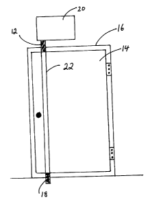
The apparatus (10) according to the Figures is comprised of a first dead bolt
(12)
positioned within the door] amb ( 16) immediately adj acent to the first end
of a door ( 14).
The first dead bolt (12) is moveable between a first locked position within
the first door
end and a second unlocked position within the door jamb (16). The apparatus
(10) is
further comprised of a second deadbolt (18) positioned within the opposite end
of the
door (14). The second deadbolt (18) is also moveable between a first locked
postion and
a second unlocked position. Finally the apparatus (10) is comprised of a means
for
actuating the first deadbolt (12) between its first locked position and its
second unlocked
position and a means for actuating the second deadbolt (18) in synchronization
with the
first deadbolt (12) between its first locked and second unlocked position.
In one embodiment, the first deadbolt (12) is positioned above the door end
when in its
unlocked position and engages an opening the upper door end ( 11 ) when moved
into its
locked position. In a further embodiment, the second deadbolt (18) is housed
in the door
5
CA 02413836 2002-12-10
(14) when in its unlocked position and engages an opening in the door jamb or
floor
(13) beneath the door (14) when in its locked position.
As depicted in Figures 3 and 4 a plurality of deadbolts may by utilized to
increase the
number of deadbolts securing both ends of the door (14). The greater the
number of
deadbolts, the more external force the door will be able to withstand.
Further, as depicted
in Figure 3, the dead bolts (12, 18) may be orientated horizontally on the
door (14).
The actuation means for the first deadbolt (12) may be an electric solenoid
motor (20)
with reversible motor means to cause the first deadbolt (12) to move between
its
unlocked and locked positions. As depicted in Figure 7, a first contact switch
(30) may
be positioned relative to the first deadbolt (12) such that when the first
deadbolt (12) is in
its retracted unlocked position, the switch (30) is engaged which in turn
shuts off the
electric motor (20). Likewise, a second contact switch (36) may placed in a
position such
that it is engaged when the first deadbolt (12) moves into its locked
position, which in
turn causes the electric motor (20) to shut off. The electric motor (20) may
also be
connected to an exterior (42) and an interior switch (40) either of which,
when used, will
cause the electric motor (20) to activate and move the first deadbolt (12)
between its
locked and unlocked positions. The first contact switch (30) and the second
contact
switch (36) may also be indicator switches for illuminating unlocked (34) and
locked (32)
indicator lights. Further, the electric motor (20) may be connected to a
remote control
switch (38) to permit the user to lock or unlock the door (14) from a
distance, either
wired or wirelessly.
The actuation means for the second deadbolt (18) may be a locking rod (22)
having a first
locked position and a second unlocked position. In its second unlocked
position the first
end of the locking rod (22) is exposed in the upper door opening and is
consequently
displaced by the first deadbolt (12) when it moves into its locked position.
This
displacement causes the locking rod (22) to move into its first locked
position. The
locking rod (22) contacts a means for biasing the locking rod (22) into its
unlocked
6
CA 02413836 2002-12-10
position. The biasing means may be compression spring (24) or such other
biasing
means as are commonly used by one skilled in the art.
The locking rod (22) may also be housed in a tube (26) affixed to the exterior
of the door
(14). The tube (26) may be constructed from steel hydraulic tubing, however
such
suggestion is not intended to be limiting to the invention claimed herein. If
a compression
spring (24) is utilized as the biasing means for the locking rod (22), an
interior tube (28)
may be used to hold the spring (24) in position within the tube (26) as is
depicted in
Figures 5 and 6.
The use and operation of the apparatus (10) will now be described with
reference to
Figures 5 and 6. To secure the door (14) the electric motor (20) is activated
and the first
deadbolt (12) is moved into its locked position causing it to protrude into
the exterior
tube (26) or door opening (11) and impinge upon the locking rod (22) as is
shown in
Figure 6. The insertion of the first deadbolt (12) into the exterior tube (26)
effectively
secures that end of the door (14) until such time as the electric motor (20)
is activated
again and the first deadbolt (12) is retracted into its unlocked position. The
entry of the
first deadbolt (12) into the exterior tube (26) exerts pressure on the locking
rod (22). The
locking rod (22) is moved into the exterior tube (26) in a direction towards
the opposite
end of the door (14) compressing the adjacent spring (24). This pressure and
corresponding movement causes the second deadbolt (18) connected to the other
end of
the rod (22) to be pushed out of the other end of the exterior tube (26) into
its first locked
position as shown in Figure 6. The second deadbolt (18) will remain in its
first locked
position until such time as the first deadbolt (12) is retracted into its
unlocked position.
This effectively secures the other end of the door (14).
To unlock the door (14), the first deadbolt (12) is retracted into its
unlocked position. As
the first deadbolt (12) is retracted, the pressure on the locking rod (22) is
released and the
spring (24) gradually decompresses pushing the locking rod (22) back to its
original
position as depicted in Figure 5. As the locking rod (22) moves to its first
unlocked
7
CA 02413836 2002-12-10
position the interconnected second deadbolt (18) simultaneously withdraws into
the
exterior tube (26) until it reaches its second unlocked position as depicted
in Figure 5.
It is anticipated the apparatus (10) as described could be adapted for
commercial use or
for use with other access points in a building that require securing such as
windows and
trap-doors. This apparatus (10) is relatively simple and inexpensive to
manufacture in
comparison to the existing electronic deadbolt systems. This apparatus (10)
also
overcomes the problem of the inherent weakness of the door and the door-frame
because
the deadbolts are not housed within the door-frame or the door and unlike the
solitary
deadbolt system, the locking rod (22) transverses the entire length or width
of the door
1 S meaning that external pressure or force on the door will be absorbed by
the entire length
of the locking rod (22).
As will be apparent to those skilled in the art, various modifications,
adaptations and
variations of the foregoing specific disclosure can be made without departing
from the
scope of the invention claimed herein.
8