Note: Descriptions are shown in the official language in which they were submitted.
CA 02414024 2002-12-02
WO 01/92851 PCT/AU01/00628
APPARATUS AND METHOD FOR MEASUREMENT OF
PERMEABILITY OR STRAIN IN PERMEABLE MATERIALS
Field of the Invention
The present invention relates to an apparatus and method for measurement of
permeability or strain in permeable materials.
l0
Background of the Invention
Permeability of a material can be defined as a rate of which a fluid flows
through the
material. The measurement of the permeability of materials, for example
concrete, is of
importance in determining the suitability of the material for various purposes
such as
fluid containment and structural life. Changes in permeability with stress
presents a
method of measuring strain in permeable material
Generally, the known methods of measurement of permeability measure a change
in
2 0 pressure of a gas applied to the material and/or depth of liquid
penetration in the
material. This method is known as the pulse test method. This method takes a
substantial time to run and may involve the preparation of special samples.
For
example, the contemporary construction industry relies heavily on laboratory
tests
carried out on samples taken during a pour of a large concrete slab or
structure to
2 5 ascertain the strength of the concrete for further construction to be
carried out. A
steady state test method is a another, more desirable, method and is employed
in the
current specification. Further, the steady state test method is practical for
the
measurement of strain. In situ testing is a further desired attribute to
reduce time taken
and cost.
CA 02414024 2002-12-02
WO 01/92851 PCT/AU01/00628
-2-
US Patent No. 4,979,390 describes one method and apparatus for testing
relative
permeability of materials. In general terms, this requires the application of
a partial
vacuum to a small test area on a piece of concrete and measuring the rate of
decay of the
vacuum to provide an index of permeability. A limitation of the method and
apparatus
described is that it is restricted to a measurement of relative permeability
and only a
single test surface of relatively small area.
International Application No PCT/AU94/00325 (WO 94/27130) Tulip Bay discloses
a
monitoring apparatus that can be used to detect faults or cracks in the
surface of or
within a structure or component. The monitoring apparatus described includes a
substantially constant vacuum source connected in series with a high impedance
to fluid
flow device that in turn is connected with one or more minuscule flaw sensing
cavities
formed on the surface of or within a structure. A differential pressure
transducer is
connected across the high impedance device to monitor the vacuum state of the
minuscule flaw sensing cavity or cavities. A pressure differential transducer
monitors
the change in vacuum condition between the minuscule flaw sensing cavities and
the
constant vacuum source. Accordingly, if there is a change in vacuum condition
in the
cavities which can arise from the formation and propagation of a crack, the
change is
detected by the transducer. Cracks of a length down to 250 micron have been
detected
2 0 using a constant vacuum source of only 200KpA below atmospheric reference.
The apparatus in Tulip Bay is particularly well suited to incorporation in
embodiments
of the present invention. Accordingly the contents of Tulip Bay are
incorporated herein
by way of reference.
Summary of the Invention
It is an object of the present invention to provide a simple, low cost in
situation, method
and apparatus for providing a measurement of the permeability of a material.
3 o It is a further object to provide a means of method and apparatus for
measuring strain in
permeable material by means of change in permeability with applied stress.
CA 02414024 2002-12-02 PCT/AU01/00628
Received 16 August 2002
-3-
According to the present invention there is provided an apparatus for a
measure of the
permeability of a material including at least:
a substantially constant fluid pressure source;
at least one fluid impervious member for juxtaposition and sealing with the
material in a manner to define, between said member and said material a
corresponding
fluid flow cavity;
a high fluid flow impedance means providing high impedance fluid
communication between said pressure source and said fluid flow cavity;
sealing means for sealing an area of a surface of the material surrounding the
l0 fluid impervious member to define a fluid impervious region between said
fluid flow
cavity and a free unsealed surface of the material; and,
means for measuring steady state differential pressure across said high fluid
flow
impedance means to provide a measure of the permeability of said material.
Preferably said at least one fluid impervious member includes a planar article
for
placement on said material.
Preferably said at least one fluid impervious member includes a sleeve
disposed in a
blind hole formed in the material, the sleeve extending for a portion of the
length of the
2 0 hole from the surface of the material and having a down-hole end spaced
above a
bottom of the hole, the sleeve forming a seal against an interior surface of
said portion
of the length of the hole, wherein said corresponding fluid flow cavity is
defined
between the down-hole end of the sleeve and the bottom of the hole.
2 5 Preferably said apparatus further includes a fluid impervious blank of a
diameter less
than the diameter of the hole and of a length less than a remainder of the
length of the
hole between said down-hole end of the sleeve and the bottom of the hole, said
blank
deposited in said hole prior to the insertion of said sleeve.
Yy
fy ~is~ ~i
CA 02414024 2002-12-02 PCT/AU01/00628
Received 16 August 2002
-4-
According to the present invention there is provided an apparatus for
providing a
measure of permeability of a material including at least:
a substantially constant fluid pressure source;
at least one first fluid impervious member each for sealed placement on the
material to define, between each first member and said material, a
corresponding first
fluid flow cavity;
first high fluid flow impedance means providing high impedance fluid
communication between said pressure source and said first fluid flow cavities;
first sealing means for sealing an area of a surface of said material
surrounding
said first fluid impervious members to define respective fluid impervious
regions
between said first fluid flow cavities and a free unsealed surface of the
material;
at least one second fluid impervious member each for sealed placement in
respective holes formed in said material in a manner to define, between said
second
members and a bottom of said holes, a corresponding second fluid flow
cavities;
second high fluid flow impedance members providing high impedance fluid
communication between said pressure source and said second fluid flow
cavities;
second sealing means for sealing an area of the surface of the material
surrounding the second fluid impervious member to define respective fluid
impervious
regions between said second fluid flow cavities and said free surface of the
material;
2 o and
means for measuring steady state differential pressure across said first and
second high fluid flaw impedance means to provide a measure of the
permeability of
said material.
2 5 According to the present invention there is also provided a method for
obtaining a
measure of the permeability of a material including at least the steps of:
providing a substantially constant fluid pressure source;
coupling said constant fluid pressure source through respective high fluid
flow
impedances to one or more fluid flow cavities formed on/or in the material;
3 0 forming respective fluid impervious seals on/or in the material about each
fluid
flow cavity to define corresponding fluid impervious regions between each
fluid flow
CA 02414024 2002-12-02 PCTlAU01100628
Received 16 August 2002
-5-
cavity and a free surface of the material; and,
monitoring measuring steady state differential pressure across said high fluid
flow impedances to provide a measure of permeability of the material.
According to the present invention there is also provided an apparatus for
providing a
measure of strain in a permeable material, said apparatus including at least:
a substantially constant fluid pressure source;
first and second fluid impervious members for juxtaposition at different
locations and
sealing with said material in a manner to define, between said members and
said
l0 material, corresponding first and second fluid flow cavities;
first and second high fluid flow impedances providing high impedance fluid
communication between respective first and second cavities and said pressure
source;
said first cavity coupled in series at a first node to said first high fluid
flow impedance,
and said second cavity coupled in series at a second node to said second high
fluid flow
impedance;
sealing means for sealing areas of a surface of the material surrounding said
first and
second fluid impervious members to define a fluid impervious region between
said first
and second cavities and a free surface of said material; and,
means for measuring steady state differential pressure across said first and
second nodes
2 o to provide a measure of strain in said material.
According to a further aspect of the present invention there is provided a
method of
obtaining a measure of strain of a material, said method including at least
the steps o~
providing a substantially constant fluid pressure source;
2 5 coupling said constant fluid pressure source through respective first and
second
high fluid flow impedances;
forming first and second fluid flow cavities on or in said material;
forming respective fluid impervious seals on/or in said material about said
first
and second fluid flow cavities to define corresponding fluid impervious
regions between
3 0 each of said fluid flow cavities and a free surface of said material;
coupling said first high fluid flow impedance in series at a first node to
said first
PCTlAU01 /00628
CA 02414024 2002-12-02
Received 16 August 2002
- -6-
cavity;
coupling said second high fluid flow impedance in series at a second node to
said second cavity; and
measuring steady state pressure differential across said first and second
nodes to
provide a measure of strain in said material.
In one embodiment, said high impedance includes a very long length of small
bore duct
which allows a minuscule flow of fluid.
In an alternate embodiment, said high impedance comprises a permeable material
such
as sintered glass, an orifice or point restriction such as a needle valve
being considered
far too impracticable due to the minuscule flow required.
The magnitude of the high fluid flow impedance should be sufficiently high as
to
produce significant pressure drop across the high impedance in response to
minuscule
flow through the high impedance.
Brief Description of the Drawings
2 o Embodiments of the present invention will now be described by way of
example only
with reference to the accompanying drawings in which:
Figure 1 is a schematic representation of an apparatus in accordance with the
first
part of the present invention;
Figure 2 is a schematic representation of an application of the apparatus of
figure
2 5 1 for providing surface permeability measurement in a bulk material;
Figure 3 is a schematic representation of an application of the apparatus of
figure
1 for providing matrix to surface permeability measurement in a bulk
material;
Figure 3A is an enlargement of portion A of Figure 3;
CA 02414024 2002-12-02 PCT/AU01/00628
Received 16 August 2002
Figure 4 is a schematic representation of an application of the apparatus of
figure
1 for providing surface to surface permeability measurement in a sample
of material; Figure 5 is a schematic representation of an application of
the apparatus of figure 1 for providing material to matrix permeability
measurement in a bulk material.
Figure 6 illustrates application of the apparatus of figure 1 for measurement
of the
permeability of a paint film.
Figure 7 is a schematic representation of an apparatus in accordance with a
second
aspect of the present invention;
Figure 8 is a schematic representation of a portion of the embodiment depicted
in
Figure 7;and,
Figure 9 is a schematic representation of an application of the embodiment
shown
in Figure 7.
Detailed Description of Preferred Embodiments
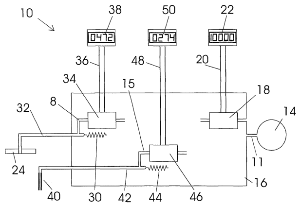
Referring to Figures 1-3A, an embodiment of the apparatus 10, in accordance
with the
first part of the present invention, for providing a measure of the
permeability of a
material 12 includes a substantially constant fluid pressure source which, in
this
2 0 embodiment is in the form of a constant vacuum source 14 (a pressure
source at a sub-
atmospheric pressure). The vacuum source 14 is coupled via duct 11 to a fluid
capacitance vessel 16 which contains a first pressure transducer 18 coupled by
electrical
conductors 20 to an amplifier and display 22 for monitoring the constant
vacuum source
14. Throughout this specification the term "fluid pressure source" is intended
to denote
2 5 a source of fluid at any particular absolute pressure.
A first fluid impervious member in the form of a fluid impervious disc 24 is
provided
for placement on a surface 26 of the material 12 to define, between the disc
24 and the
surface 26 a first fluid flow cavity 28 (see Figure 2). The disc 24 is coupled
to the
3 o vessel 16 and thus to the constant vacuum source 14 via a high impedance
fluid flow
means in the form of a length of a small bore duct such as restriction tube 30
(typical
PCT/AU01 /00628
CA 02414024 2002-12-02
Received 16 August 2002
_g_
dimensions being less than 0.30mm bore and length in excess of 3 metres) .
That is, one
end of the impedance 30 is coupled to the vessel 16 with the other end coupled
via a
conduit 32 to the disc 24. A second pressure transducer 34 is coupled across
the
impedance 30 and coupled by conductors 36 to an amplifier and digital display
38.
A second fluid impervious member in the form of a sleeve 40 is coupled via a
conduit
42 and high fluid flow impedance in the form of restriction tube 44 of the
same
dimensions as tube 30 to the vessel 16 and thus the constant vacuum source 14.
Pressure transducer 46 is effectively coupled across the fluid impedance 44
between the
l0 sleeve 40 and the vacuum source 14. Additionally the transducer 46 is
coupled by
electrical conductors 48 to an amplifier and digital display 50.
The sleeve 40 is disposed in a blind hole 52 formed in the material 12. The
sleeve 40
extends from the surface 26 of the material for a portion of the length of the
hole 52 so
that a down-hole end 54 is spaced from the bottom 56 of the hole 52. The
sleeve 40
forms a seal against the interior surface of the portion of the hole 52 for
which it extends
(the gap shown between sleeve 40 and the interior surface of hole 52 in Figure
3A is for
clarity of illustration only, the gap does not actually exist). A fluid flow
cavity 58 is
defined between the down-hole end 54 of the sleeve and the bottom 56 of the
hole. This
2 o cavity is placed in fluid communication with the vacuum source 14 by
conduit 42 which
couples to an axial bore 59 provided in the sleeve 40.
The cavities 28 and 58 are configured so that the surface area of the material
under disc
24 in fluid communication with the vacuum source 14 is substantially the same
as the
2 5 surface area of the hole 52 between down-hole end 54 of the sleeve 40 and
the bottom
56 of the hole 52, inclusive of the area of the bottom face of the hole 52.
Associated with the disc 24 and thus the first fluid flow cavity 28 is a fluid
impervious
seal 60. The seal 60 forms a seal about the periphery of the disc 24 and
extends radially
3 0 outwardly on the surface 26 of the material 12. The seal 60 thus forms on
the surface 26
of the material a fluid impervious area or region 62 between the fluid flow
cavity 28 and
CA 02414024 2002-12-02
WO 01/92851 PCT/AU01/00628
-9-
the "free surface" of the material 12. The term "free surface" refers to any
surface of the
material 12 that is open to fluid communication with the surrounding
atmosphere/environment without third party impediment, this can include the
surface of
a hole or cavity formed in the material which is in fluid communication with
the
surrounding atmosphere/environment, (such as depicted in Figure 5 as explained
in
greater detail below).
A second fluid impervious seal in the form of a seal 64 forms a seal about the
periphery
of the sleeve 40 at surface 26 and extends radially outwardly on the surface
26 of the
material 12. The seal 64 forms a fluid impervious area or region 66 between
the fluid
flow cavity 58 associated with the sleeve 40 and the free surface of the
material 12 (refer
Figures 3 and 3A), with the radial width of seals 60 and 64 being
substantially the same.
When the apparatus 10 is applied to the material 12 it will be appreciated
that after an
initial transient period a constant (steady state) vacuum will exist in the
fluid flow cavity
28 beneath disc 24 and the fluid flow cavity 58 beneath the sleeve 40. This
creates a
pressure differential between the cavities 28, 58 and the surrounding
environment.
Assuming that the material 12 has some degree of permeability, air is able to
permeate
through the material 12 from beyond the fluid impervious areas/regions 62, 66
to the
2 0 fluid cavities 28, S 8 respectively. This flow produces a steady state
differential pressure
across the corresponding high fluid impedance restriction tubes 30, 44 which
will be
displayed on corresponding displays 38 and 50. These displays can be directly
calibrated into a scale of permeability. Accordingly the apparatus 10 can
provide a
measure of the specific permeability of the material 12. Particularly the
apparatus 10
2 5 can provide either a measure of specific surface permeability via disc 28,
of or specific
matrix permeability via sleeve 40, or both.
In order to reduce the time for stabilisation of the vacuum state in the
bottom of hole 52
at the initial application of the apparatus 10 when used to provide a measure
of matrix
3 0 permeability, a blank 68 can be provided for insertion into the hole 52
between the
down-hole end 54 of the sleeve 40 and the bottom of 56 of the hole. The blank
68 is of
CA 02414024 2002-12-02
WO 01/92851 PCT/AU01/00628
_10_
a diameter less than that of the hole 52. The purpose of the blank 68 is
simply to reduce
the volume of the portion of the hole constituting the fluid flow cavity 58
thereby
reducing the time required to evacuate the bottom of the hole prior to the
commencement of the permeability measurement.
In order to produce highly accurate and meaningful results with repeatability,
it is
preferable to optimise the'ratio of the fluid impervious areas or regions
62/66 with the
surface areas of the material within cavities 28, 58. Take for example the
arrangement
shown in Figure 2. If the fluid impervious area 62 is too small then a fluid
flow path
between the cavity 28 and the free surface of the material 26 will be too
short to provide
an accurate measurement of the permeability of the material. That is, there
will not be
sufficient fluid flow path length in the material 12 to provide an accurate
reading of
permeability. It is known however that after a certain distance or radius has
been
reached from the periphery of the cavity 28 there is insignificant difference
in
permeability measurement by extending the fluid impervious area 62. The ratio
between
the outer diameter of the area 62 and the cavity 28 can be found empirically
for a
particular material. 6: 1 is a typically ratio. Additionally, it is preferable
that the areas
covered by the seals 60 and 64 are approximately the same.
2 0 In general application, a plurality of discs 24 and/or sleeves 40 with
corresponding seals
60/64 can be arranged in line groups connected to one high fluid flow
impedance or as
simultaneous surface and matrix tests connected to two or more high fluid flow
impedance restriction tubes. Of course the scale of impedance needs to be
compensated
if the use of multiple cavities alters the sum total exposed area of the
cavities 28 and 58
The apparatus depicted in Figure 1 is configured to provide a measure of both
surface to
surface permeability of the bulk material 12 using the disk 24 as shown in
Figure 2 and
surface to matrix permeability of the bulk material 12 using the sleeve 40
depicted in
Figure 3. It is however not essential that the apparatus 10 be configured to
3 0 simultaneously take both surface to surface and surface to matrix
permeability
measurements. Either one of the high impedance restriction tubes 30 or 44 can
be de-
CA 02414024 2002-12-02
WO 01/92851 PCT/AU01/00628
-11-
coupled so that the apparatus 10 takes the measurement of only surface to
surface
permeability or surface to matrix permeability of the bulk material 12.
As mentioned above, International Application No. PCT/AU94/00325 (Tulip)
describes
an monitoring apparatus particularly well suited for incorporation into
embodiments of
the present invention. With particular reference to Figure 1, the impedances
30, 44,
transducers 34, 46 and displays 30 and 50 may all take the form of that
described in
Tulip Bay. The particular advantage of incorporating the Tulip Bay apparatus
is that it
enables detection of fluid flow well below the lower limits of conventional
mass flow
1 o meters. Further, if desired, the sensitivity of the apparatus can be
increased infinitely by
increasing the impedance of the high fluid flow impedances.
Further to this, in a further application , the apparatus 10 can be
configured, as
illustrated in Figure 4, to take surface to surface permeability measurement
of a sample
unit of material such as a brick 70. (In this embodiment the brick is
illustrated as being
provided with a plurality of apertures 71, but the provision of apertures is
not necessary.
The embodiment is equally applicable to a solid brick). In this application, a
fluid
impervious means in the form of a rectangular sheet 24' that is sealed to
outer peripheral
surface 72 of the brick 70 with a perimeter fillet of an adhesive 74. A
corresponding
2 0 cavity (hidden) is defined between the sheet 24' and the underlying area
of the surface
72 of the brick 70. The cavity beneath the sheet 24' is in fluid communication
with the
high fluid impedance 30 via conduit 32', ie, in terms of Figure l, the disc 24
is replaced
with the sheet 24'. The entirety of the remainder of the surface 72 of the
brick 70
including the surface area of the apertures 71 but excluding a rectangular
area 26' is
2 5 sealed with a sealing compound: The area 26' is spaced a distance from the
sheet 24'
and is of the same area as the surface area of the brick 70 beneath the sheet
24' which is
in fluid communication with the vacuum source 14. The operation of the
apparatus 10
in the embodiment shown in Figure 4 allows a measure of the permeability of a
surface
layer of the brick 70 between sheet 24' and area 26'.
Figure 5 illustrates a configuration for making matrix to matrix permeability
CA 02414024 2002-12-02
WO 01/92851 PCT/AU01/00628
-12-
measurement in a bulk material 12. In comparison to the apparatus 10 depicted
in
Figure 1 and the arrangement in Figure 3, the configuration in Figure 5
differs in that
the disc 24 is not used, the free surface 26 is the surface area of a lower
part 76 of a hole
78 formed in the bulk material 12 and, the seal 64 seals a greater surface
area of the
material 12. In this regard, the seal 64 extends along the surface of the
material 12 from
the sleeve 40 for a distance substantially greater than the distance between
holes 52 and
78. Also, the seal 64 extends for a portion of the length of the hole 78 to
the lower
portion 76. However, the seal 64 does not completely block the hole 78 and a
communication channel 80 is left or otherwise formed to allow fluid
communication
1 o between the suxface 26 of the bottom portion of the hole 76 and the
atmosphere. The
area of the surface 26 is approximately the same as the surface area of the
hole 52
beneath the down-hole end 54 of the sleeve 40.
Of course matrix to matrix permeability measurement of a sample of material
could be
conducted using substantially the same configuration of apparatus depicted in
Figure 5,
the only additional requirement is that either the seal 64 or another seal or
sealing
compound would seal the whole surface of the sample in a similar manner as
described
in relation to and as illustrated in Figure 4.
2 0 In the above described embodiments, the constant fluid pressure source 10
has been
described as a vacuum source. However the source can be a liquid such as water
at a
substantially constant pressure. This allows measurement of water permeability
of the
material 12. In such an application, the impedance of restrictive tubes 30 and
44 must
be greatly increased to improve sensitivity to the reduction in the permeating
fluid flow
2 5 rate of water with respect to air. Typically, a length of a nominal
30metres would be
required to measure permeability rates of less than 1 x 10'" metres per second
Measurements made in accordance with the second embodiment depicted in Figure
4
may not directly relate to measurements in accordance with the set-up shown in
Figures
3 0 2 and 3 unless empirical determination of the required tests surface and
atmospheric
venting surface dimensions at a distance between said surfaces is obtained.
CA 02414024 2002-12-02
WO 01/92851 PCT/AU01/00628
_13_
Figure 6 illustrates application of the apparatus of figure 1 for measurement
of the
permeability of a paint film. A sectional view shows a paint film 90 that has
been
prepared by coating onto a surface which has subsequently been dissolved. The
film 90
is then laid onto a freely permeable support medium 92 contained within a
fluid
impervious means in the form of an impermeable receptacle 94 and peripherally
sealed
(96) to the receptacle 94 by a peripheral seal 96. Here, a fluid flow cavity
28" is defined
between the paint film 90 and the receptacle 94 by the medium 92. Duct 32a
provides
fluid communication to the apparatus 10 of Figure 1 between cavity 28" and the
constant vacuum source 14 of Figure 1, in a similar way to duct 32, via a
corresponding
high fluid impedance and transducer. The film permeability can now be
determined and
the effects of environmental exposure can be compared at intervals for
degradation.
Figure 7 is a schematic representation of an apparatus in accordance with a
further
embodiment of the present invention for measuring strain in permeable
material.
Referring to Figures 1 and 7, the fluid capacitance vessel 16 has been removed
for
clarity. The vessel 16 normally serves as a convenient containment of
components and
smoothes pulsation that may evolve from the constant vacuum source 14. It will
be
obvious that by connecting duct 11 of Figure 1 to the pressure transducers 18,
34, and
2 0 46, and the high fluid impedance tubes 30 and 44, the vessel 16 is
redundant and
simplifies Figure 7.
The drawing of Figure 7 has been arranged to represent a system l0a which is a
fluid
analogy of the familiar wheatstone bridge. In particular, it resembles a
strain gauge half
bridge in which two "permeability actuated " analogous strain gauges R3 and R4
are
2 5 employed.
Referring to Figures 7, 8 and 9, a constant vacuum source 14a is connected via
duct l la
to high fluid impedance tubes 30a and 44a (R1 and R2), thence to two cavities
28a and
28b respectively, formed on a surface 100 of a test substrate 101. The R3 and
R4
3 0 resistor symbols represent resistance to atmospheric air permeation
through the material
101 being investigated, into the cavities 28a and 28b. The atmospheric air
ingress into
CA 02414024 2002-12-02
WO 01/92851 PCT/AU01/00628
-14-
the cavities 28a and 28b, against the resistance of the test material 101, is
represented by
the white arrow heads.
Similar to a strain gauge installation the cavities 28a and 28d respond to
elongation or
compression of a test surface to which they are attached. Unlike strain gauges
wherein a
change in electrical resistance occurs, the cavities experience a change in
vacuum
condition due to a change in the permeability of the test material 101 partly
defining the
cavities 28a and 28b. In like manner to strain gauges in a half bridge
configuration, one
cavity is attached to a surface undergoing tensile loading whilst the other is
attached to
a surface undergoing compressive loading.
In a further analogy to a strain gauge installation, a pressure difference is
measured
across a differential pressure transducer 34a fluidly connected by ducts 32a
and 42a to
the R1/R3 and R2/R4 junctions respectively. Conductors 20a provide electrical
connection to an amplifier and display 38a. In order to achieve bridge balance
under no
load, the high fluid impedance tubes 30a and 44a (Rl and R2) can be made
adjustable.
This can be facilitated by spiral winding the tubes and containing between
adjustable
pressure plates. Alternatively, one such adjustable device can be placed as a
series
connection as appropriate with one of the cavity connections to duct 32a or
42a
Figure 8 shows detail of a typical cavity performing a function analogous with
a strain
gauge, for example, representing 28a (R3) of Figure 7.
A portion of concrete 101 has been sectioned to reveal a cavity 28a defined
under an
elongate strip of impermeable material 24a sealed peripherally to the concrete
I01 by a
surface coat of a fluid impermeable seal 120. Similarly, a second elongate
strip of
impermeable material 25a defines a cavity 29a and is arranged at a
predetermined
parallel distance from 24a/28a. The cavity 29a serves as a weather proof
atmospheric
reference being fluidly connected to atmosphere via duct 33a. The cavity 24a
is fluidly
communicated via duct 32a to the remainder of the system l0a of Figure 7 and
hence is
3 0 connected to the vacuum source 14a.
With specific reference to Figure 8, a permeable air flow varying in response
to a
CA 02414024 2002-12-02
WO 01/92851 PCT/AU01/00628
-15-
varying stress, indicated by the black arrow, is illustrated by the white
arrows. The flow
is shown between the atmospheric cavity 29a and the vacuum cavity 28a. Micro-
cracks
in the surface of the concrete 101 open and close with variation in applied
stress to
produce this effect. 'The fluid impermeable seal 120 is extended sufficiently
to provide
S weather protection, especially from rain.
Figure 9 shows application of the system l0a to a high rise building 115
constructed of
concrete (101).
Cavities 28a and 28b are attached to surfaces 100 on the sides of the building
as viewed
to measure strain due to a force, represented by a black arrow, produced for
example by
wind loading.
A correction to gas permeability measurement due to moisture content in
concrete can
be provided. This can be achieved directly by electrical conductivity
measurement.
Alternatively, by measuring the amount of water in the minuscule airflow over
a
predetermined time, a correction may be derived from a method such as chemical
absorption, or a device wherein minuscule capacitor plates are chilled to
collect
moisture and alter capacitance and hence frequency in an electronic oscillator
circuit.
2 0 l~Tow that embodiments of the present invention have been described in
detail it will be
apparent to those skilled in the relevant arts that numerous modification and
variations
may be made without departing from the basic inventive concepts. For example,
the
apparatus shown in Figure 1 depicts the use of a single disc 24 for providing
surface
permeability and a single sleeve 40 for providing matrix permeability. however
2 5 multiple discs 24 andlor sleeves 40 can be incorporated in order to test
large areas of
material and/or to provide both surface permeability and matrix permeability
measurements.
In another variation, permeability measurement of a layer of concrete at a
selected depth
3 0 may be accomplished by providing two elements of the configuration of
Figure 3 to
produce a fluid flow, one to the other, and having all significant surfaces
sealed.
CA 02414024 2002-12-02
WO 01/92851 PCT/AU01/00628
-16-
Further, the inclusion of the vessel 16 is not essential and largely
determined by the
capacity of the constant pressure source.
With respect to strain measurement, liquid instead of gas may be appropriate
such as in
submerged applications. Further, in the embodiments depicted in Figures 7-9,
the
cavities formed on the material for which the strain is measured are
illustrated as being
formed on the surface of the material. However in a similar manner as
illustrated in
Figure 3 and 3a, the cavities can be formed internally of the material.
All such modifications and variations together with others that would be
obvious to a
person of ordinary skill in the art are deemed to be within the scope of the
present
invention the nature of which is to be determined by the above description,
and the
appended claims.