Note: Descriptions are shown in the official language in which they were submitted.
CA 02414141 2002-11-25
WO 01/96036 PCT/US00/16343
SPRAY CLEANING DEVICE
Technical field
The present invention relates to a spraying device comprising a container, a
spray head and a water purifier. In an alternative embodiment the invention
relates to a container suitable for use in with a spraying device, comprising
a
water purifier. The purifier is preferably located inside the container and
cooperates with the spray head. The purifier is preferably a filter, which is
preferably a layered bed of ion exchange resins. In another preferred
embodiment the container comprises a hydrophilic-surface modifying cleaning
composition. The spraying device preferably also comprises means for
connection to a hose and can be used for, for example, cleaning vehicles,
exterior surface of windows etc.
Background
Products for cleaning hard surfaces are widely available on the market. These
products are used for two purposes, the first being to clean soil from the
surface
3o and the second being to leave the surface with an aesthetically pleasing
finish
e.g. spot-free and/or shiny. However products available on the market often
require rinsing with water after use. Typically when the water dries from the
1 ~
CA 02414141 2002-11-25
WO 01/96036 PCT/US00/16343
surface water-marks, smears or spots are left behind. These water-marks, it is
believed may be due to the evaporation of water from the surface leaving
behind
deposits of minerals which were present as dissolved solids in the water, for
example calcium or magnesium or sodium ions and salts thereof or may be
deposits of water-carried soils, or even remnants from a cleaning product for
example soap scum. One solution to this problem as provided in the prior art
has
been to clean the surface with a cleaning composition which modifies the
surface
to leave a hydrophobic finish. Thus during the cleaning process the majority
of
the water drains rapidly from the surface and the remainder forms discrete
1o droplets or beads on the surface because of the hydrophobic interactions.
However the Applicant has found that although the surface dries quickly, it is
also
left with noticeable spots or marks, known as water-marks. This problem is
particularly apparent when cleaning ceramic, steel, plastic, glass or painted
surfaces. A means of solving this problem, known in the art is to dry the
surface
using a cloth or chamois before the water-marks form. However this drying
process is time consuming and requires considerable physical effort.
W097/48927 describes a process for cleaning the exterior surface of a window
using a spray gun and a means for preparing purified water. The windows are
first cleaned with a cleaning composition and then rinsed with purified water.
Whilst the use of this spray gun, may initially solve the problem of residual
water
marks on surfaces on drying, the Applicants have found that the spray gun has
an inefficiently short life-span which thus requires the user to replace the
ion-
exchange resin cartridge after each use. Moreover the cleaning compositions
described in W097/48927 render the surfaces treated therewith, hydrophobic. It
thus an object of the present invention, to provide a spraying device and
container comprising a new purifier which has improved capacity versus the
purifier described in W097/48927.
In another aspect of the present invention the purifier is located inside the
cavity
of the container. In another aspect the container is suitable for attachment
to a
2
CA 02414141 2002-11-25
WO 01/96036 PCT/US00/16343
spray head to form the spraying device described in the present invention. The
benefit in locating the purifier inside the container is in the ease of
assembling
the spraying device, allowing the user to quickly and accurately align the
input
and output ports of the purifier and the means for removing the cleaning
compositions from the container, with the valve system in the spray head. A
further benefit of locating the purifier inside the cavity of the container is
that it
can not be accessed by the user. The user is therefore discouraged from using
the spraying device without also using the purifier, since this would lead to
poor
performance results. Moreover, since the purifier can not be regenerated,
1o locating the purifier inside the container also ensures that the user
replaces the
purifier at the same time as he replaces the cleaning composition. For this
reason the container comprising cleaning composition and the purifying device
can then be made available as a combined recharge unit.
In another aspect of the present invention there is described a container
suitable
for use as a component of the spraying device comprises a purified and a
composition capable of rendering the surface treated, hydrophilic. The
Applicants
have found that cleaning compositions which render the surface hydrophilic
rather than hydrophobic provide improved cleaning performance, but can also be
2o rinsed from the surface treated more easily.
Summary of the Invention
According to the present invention there is provided a hand-held spraying
device
comprising a container (1), a spray head (11) and a water purifier (30),
characterised in that the purifier is located inside the cavity of the
container.
In a further aspect of the present invention there is provided a hand-held
spraying device comprising a container (1), a spray head (11) and a water
purifier (30), characterised in that the purifier comprises a layered ion-
exchange
bed.
3
CA 02414141 2002-11-25
WO 01/96036 PCT/US00/16343
In yet a further aspect of the present invention there is provided a spraying
device comprising a container (1), a water purifier (30) and a spray head
(11),
characterised in that the spray head comprises an integrated delivery system
designed to facilitate compliance with a three or more step wash and rinse
process.
In a further aspect of the present invention there is provided a container (1)
comprising a water purifier (30) located inside the cavity of the container,
being
1o adapted for use with the spraying device according to any of the preceding
claims.
In yet another aspect of the present invention there is provided a container
(1)
comprising a water purifier (30) and a cleaning composition designed to render
a
surface treated therewith hydrophilic and comprising a hydrophilic surface
modifying component.
In a further aspect of the present invention there is also provided a
container (1)
comprising a water purifier (30) wherein the purifier comprises a layered bed
of
2o an ion-exchange resin.
Detailed Description of the Invention
Figure 1 is perspective view of the spraying device
Figure 2 is a front view of the spraying device
Figure 3 is a plan view of the spraying device
Figure 4 is a cross-sectional view of the spraying device through A-A of
figure 3
Figure 5 is a cross-sectional view of the spray head through A-A of figure 3
Figure 6 is an exploded view of the spraying device
4
CA 02414141 2002-11-25
WO 01/96036 PCT/US00/16343
The spray device of the present invention can be used to clean hard surfaces
for
example ceramic, porcelain, enamel, vinyl, no-wax vinyl, linoleum, melamine,
glass, any plastics, plastified wood, metal, especially steel and chrome
metal,
varnished or sealed surfaces, floors, walls, tiles, windows and especially,
the
exterior surfaces of a vehicle, e.g. painted, plastic or glass surfaces and
finishing
coats.
In a preferred embodiment the spraying device is a hose-end venturi system and
thus the spraying device may preferably comprise a means of attachment to a
1o conventional garden hose. Optionally an extension attachment can be used to
reach areas otherwise not easily accessible such as higher altitude windows or
car rooftops. Preferably the spray device also comprises a valve system which
is
designed to ensure that the user complies with a washing and rinsing process
involving a washing step, an unpurified water rinsing step and a purified
water
rinsing step. More preferably the process comprises an unpurified water
rinsing
step before the washing step in order to pre-wet the surface. The valve system
also preferably incorporates a selector system, for example a rotatable dial,
allowing the user to choose between the wash, unpurified rinse and purified
rinse
settings. In the wash setting the valve system is aligned such that water from
the
2o hose enters the device via the water inlet, and mixes with the cleaning
composition in a mixing chamber which is then sprayed onto the surface to be
cleaned. More preferably, the device is a venturi type system whereby a vacuum
created by water passing over the top of a means for removing the cleaning
composition from the container, e.g. a dip-tube extending into the cleaning
composition stored in the container, withdraws cleaning composition from the
container. The cleaning composition and water is then sprayed onto the surface
to be cleaned. Once the selector is moved into the rinse setting, the valve
redirects the influx water away from the cleaning composition or purifier and
water is sprayed onto the surface to rinse the cleaning composition and dirt
from
the surface cleaned. The selector system can then be placed in the purified
rinse
setting, whereby the water is passed through a purifier system before being
5
CA 02414141 2002-11-25
WO 01/96036 PCT/US00/16343
sprayed onto the surface. The purifier removes ions and other impurities from
the
rinse water and hence leaves the surface onto which the purified water has
been
sprayed, without water marks or residues upon drying.
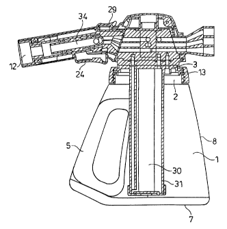
Container
The container, 1, of the present invention comprises at least one compartment,
however it is also envisaged that the present container may comprise more than
one compartment, preferably two, three or even four compartments. Said
container can be either substantially rigid, flexible or collapsible. Said
container
lo can be made from plastic, glass, metal or metal alloy or a combination
thereof.
More preferably the container, including all elements of the container, are
made
from plastic, more preferably thermoplastic material. Examples of preferred
thermoplastic materials include polypropylene (PP), polyethylene (PE), high
density polyethylene (HDPE), polyethylene terephthalate (PET) or a combination
thereof.
The container, 1, is preferably substantially rigid, and comprises top 6,
bottom 7
and peripheral side 8 walls defining an internal cavity. The bottom wall, 8,
of the
container preferably comprises a "push-up" where the surface of the container
in
contact with the cleaning composition is raised, for example is inclined or
bowed
to aid the stability of the container.
The container,l, is preferably provided with at least one venting hole. The
venting holes provide at least two functions, namely it allows the escape of
any
gas developed by the cleaning composition during storage and allows the
equalization of the pressure in the container once the cleaning composition
has
been removed. The vent hole, where present, may be located in any suitable
place on the container walls, however the vent hole is preferably present on
the
top wall of the container or more preferably in the plate (described in detail
later).
In a preferred aspect the vent hole is covered, but even more preferably
6
CA 02414141 2002-11-25
WO 01/96036 PCT/US00/16343
comprises a one-way valve. In each case the cover or valve prevents the flow
of
the composition through the vent hole, but does not impede the escape of gas.
In a preferred embodiment, the container is equipped with a neck portion,2,
which defines an opening and provides a location of attachment of the spray
head. The neck portion,2, can be located at any position on any wall of the
container, but is preferably located in a position on the top wall. The neck
can
have any suitable shape, but is preferably substantially cylindrical. In one
embodiment, the neck portion comprises at least one screw thread which may
cooperate with a screw thread of the spray head or a threaded collar, 13. In
another embodiment, the spray head may be attached to the neck by means of a
groove or protrusion on the neck to which at least one corresponding
protrusion
or groove of the spray head is clipped in a releasable or non-releasable
manner.
Where present the neck portion can be made from any of the materials as listed
above, however the neck portion is preferably rigid. In a preferred embodiment
the container comprises a closure such as a cap which cooperates with the neck
portion of the container. Alternatively the closure may comprise a plate which
is
inserted into the neck portion of the container.
2o The container optionally comprises at least one gripping means, 5. The
gripping
means, 5, may be for example a handle. The handle may be integral to or and an
extension of the multiple-compartments. Alternatively the gripping means, 5,
may
comprise an area of the surface of the container which is modified to
facilitate
grip by the user. An example of this second embodiment, may be for example the
texturing of the container surface to increase friction.
The process used for making a container, 1, as described above depends on the
size, shape and materials of the container being made. In the case where the
container is rigid, suitable manufacturing processes may be appropriately
chosen
3o by a skilled person. Such processes may include, but are not limited to:
blow
molding, injection molding, injection-blow-molding, or extrusion-blow-molding.
In
7
CA 02414141 2002-11-25
WO 01/96036 PCT/US00/16343
the case where the container is flexible and/or malleable, suitable
manufacturing
processes can again be selected by the skilled person. However such processes
include, but are not limited to: blow molding; extrusion-blow-molding; and
injection-molding. In the latter case, a bag, sachet or pouch may also be
produced by a forming and sealing process, with the rigid neck being sealed or
integrated on one side of the bag, sachet or pouch.
Spray Head
The spray head, 11, preferably comprises a number of parts, for example a
1o means for connection to a hose 12, attachment means for attachment of the
spray head to the container 13, means for removal of the cleaning composition
from the container 15, a valve system suitable for controlling water flow
through
the spray device and means for operating said valve system 25, at least one
spray nozzle 21 and an operating switch or trigger 24.
In a particularly preferred embodiment the spray head 11, is a hand-held hose
end spraying head and thus also comprises a means of attaching the spray head
to a hose, 12. Such attachment means may comprise any known attachment
available in the prior art. Preferred attachment means 12, include a threaded
2o hose coupling or a quick disconnect snap fitting.
The spray head 11, may be attached to the container using any suitable means
for example snap fit, screw, bayonet, threaded collar fittings. The spray head
is
preferably fitted with a threaded collar 13, comprising a screw thread which
then
cooperates with a screw thread on the container neck. Alternatively, the spray
head may be attached to the container, using an interlocking or "lock & key"
system which facilitates alignment of the container and the valve system in
the
spray head. In a preferred embodiment of the present invention, the spray head
is attached to the container using both the "Lock & Key" system and the screw
collar. In another alternative embodiment, a plate, 3, may be inserted into
the
neck of the container or alternatively between the container and spray head.
The
8
CA 02414141 2002-11-25
WO 01/96036 PCT/US00/16343
plate, 3, may be useful as a closure to cover the container, retaining the
cleaning composition within the container until required and preventing it
from
damaging the mechanisms of the spray head. Where the plate, 3, is present it
may be preferable for the plate to provide the cooperating surface of the
"lock
and key" system, where present, which then cooperates with that of the spray
head, 14. Furthermore in this embodiment it is then also preferable to use the
collar attachment system 13, described above, to attach the spray head to the
container.
1o The spray head 11, comprises means for removal of the cleaning composition
from the container 15. The spray head 11, preferably comprises or has attached
thereto a dip-tube 15, which extends into the cleaning composition. In this
embodiment the passage of influx water from the hose passing over the top of
the dip-tube, creating a vacuum which withdraws the cleaning composition from
the container and into the spray head. In a particularly preferred embodiment
the
plate 3, may be used to suspend the dip-tube 15, within the cavity of the
container. Alternatively the influx water may be allowed to flow into the
container, mix with the cleaning composition and then flow out of the
container
via the same or another opening in the container. Alternatively the container
may
2o be pressurised so as to force the cleaning composition from the container.
In this
latter embodiment the container preferably does not comprise any vent holes.
The valve system comprises any system which allows the user to select
different
settings on the device. Preferably the valve system is capable of facilitating
the
users compliance with a defined wash and rinse process comprising at least a
washing step, an unpurified water rinsing step and a purified water rinsing
step.
The valve system preferably comprises three channel which direct the inlet
water
to the means for removal of cleaning composition, the purified or directly to
the
spray nozzle. Preferably the valve system comprises a first channel, 18, which
directs inlet water to the means for removal of the cleaning composition, a
9
CA 02414141 2002-11-25
WO 01/96036 PCT/US00/16343
second channel 19, which directs inlet water directly to a second spray nozzle
and a third channel, 20, which directs inlet water to the purifier. In one
preferred
embodiment the valve system comprises a rotatable valve core, 16, seated in a
valve housing, 17, comprising a first 18, a second 19 and a third channel 20.
The valve core 16, can be selectively rotated such that the first channel 18,
aligns with the inlet water and the means for removal if the cleaning
composition
from the container 15, for example the dip-tube 15. The pressure of the water
passing over the opening of the dip-tube creates a vacuum. The vacuum causes
the withdrawal of cleaning composition from the container into the spray head,
where it mixes with the inlet water. The mixture of cleaning composition and
water is then sprayed from a spray nozzle 21. The valve core 16, may then be
rotated such that the second channel 19, is aligned with the inlet water and
is
directed straight to a spray nozzle 22, during the unpurified rinse water
setting.
Finally, the Valve core 16, may be rotated such that the third channel 20, is
aligned with the inlet water and the purifier 30. During this purified rinse
water
setting, water passes through the purifier 30, to produce purified rinse water
which is then sprayed through a spray nozzle 23.
In an alternative embodiment the entire valve system, core 16, plus housing
17,
may be rotated which provides a channel between the influx water and the dip-
tube during the wash setting, the purifier during the purified rinse setting
and
neither during the unpurified rinse setting. The spray head preferably
comprises
a means for operating the valve system, such as a selector dial or switch 25.
The spray nozzle defines the orifice from which the unpurified water, purified
water and/or cleaning composition is sprayed. In an alternative embodiment,
the
spray head may be equipped with two or more, spray nozzles one for each or a
combination of each of water, purified water or cleaning composition. Most
preferably the spray head 11 comprises three spray nozzles one for spraying
the
cleaning composition 21, the unpurified water 22, and the purified water 23.
The
spray nozzle may additionally be fitted with an attachment to allow the user
to
CA 02414141 2002-11-25
WO 01/96036 PCT/US00/16343
change the spray pattern of fluid sprayed from the device. Thus the user may
choose a fine mist spray, a directed forceful spray or any pattern in between.
Any
such attachment known in the prior art and suitable for achieving this
function
may be used herein. Importantly, the spray nozzle may and preferably does
provide a second benefit which is the control of the flow rate of fluid
through the
device. The consequence of such control is that the amount of cleaning
composition sprayed can be controlled to as to ensure that the correct amount
of
composition is used per wash. Even more preferably, controlling flow rate also
means that the residence time of influx water in the purified can also be
1 o controlled, so as to permit optimised filtration at preferably less than 2
gallons per
minute.
The spray head 11, also preferably comprises an operating switch 24, such that
when the switch is in the 'on' position a valve, is opened to allow the influx
of
water through the device and when the switch 24, is in the 'off' position the
valve
reverts back to it's original position, inhibiting the flow of influx water.
The valve
may be electrically opened, but is preferabiy mechanically opened. Hence in a
particularly preferred embodiment the switch comprises a trigger 35, a spring
and
a plunger, 34. The user applies pressure to the trigger 35, which then causes
the
spring to compress, pushing the plunger 34, and opening the valve. Once
pressure has been removed from the trigger 35, the spring allows the plunger
34,
to resume the original position, closing the valve. In a preferred embodiment
the
switch also comprises a locking system 29, such that the switch and valve can
be
maintained in the open position until the lock is removed.
In a preferred embodiment the spraying device, more preferably the spray head
11, comprises a visual indicator that signals to the user that the device is
at
different stages of the wash and rinse process. For example the indicator may
signal when the cleaning composition is being sprayed from the device, but
more
preferably signals when the purified rinse water is being sprayed. The visual
indicator comprise a light source which illuminates when the predetermined
step
11
CA 02414141 2002-11-25
WO 01/96036 PCT/US00/16343
or steps are in operation. In a preferred embodiment the visual indicator is a
difference in spray pattern of fluid from the device between the unpurified
rinse
water spray and the purified rinse water spray. This is achieved using
different
spray nozzles for each of the unpurified and purified rinse water settings.
The valve system and spray nozzles discussed above are housed in a water tight
body. The body may be made using any suitable material, but is preferably made
from plastic, more preferably thermoplastic material and is preferably rigid.
Examples of preferred thermoplastic materials include polypropylene (PP),
io polyethylene (PE), high density polyethylene (HDPE), polyethylene
terephthalate
(PET) or a combination thereof. In a preferred embodiment the body comprises
a left 27, and right 28, segment which fit over the left and right sides of
the valve
system, allowing an opening for the spray nozzle(s). The body segments are
then attached to one another using any suitable means, preferable the segments
are screwed together. The spray head 11, also preferably comprises a handle
26, to facilitate grip by the user. Where said handle 26, is present it
preferably
forms part of the body and incorporates the operating switch 24, and lock 29.
Water Purifier
2o The spraying device of the present invention also comprises a water
purifier, 30,
which is in one embodiment located in the container cavity. The water purifier
30,
is preferably a filter and comprises any known filtering material. In a
preferred
embodiment the purifying material is an ion exchange resin. Even more
preferably the purifying material is a mixture of several ion exchange resins
or
most preferably layers of different ion exchange resins. The ion exchange
resin is
selected from the group of strong acid cation (SAC), strong base anion (SBA),
weak acid cation (WAC) and weak base anion (WBA) ion exchange resins.
Strong acid or strong base ion exchange resins are those which comprise a
strong acid or base functionality. A strong acid or strong base functionality
are
those which have a pKa or pKb, respectively, of higher than 2.5. A weak acid
or
base functionality is defined by a pKa or pKb, respectively, of less than 2.5.
The
12
CA 02414141 2006-07-24
purifying device may preferably comprise a random mixture of strong acidiC and
strong basic ion exchange resins. However in one especially preferred
embodiment the purifyin'g device comprises a sequential bed design of three
different ion exchange resins, namely weak acidic, strong acid and weak basic
and even more preferably in that order.
By SAC ion exchange resin it is meant a resin that filters all cations
including
calcium, magnesium and sodium. Examples of SAC ion exchange resins
include, but are not limited to Rohm and Haas IRN77, 1500H and Purlite C100H.
By SBA ion exchange resin it is meant a resin that filters all anions
including
sulfate, chloride, carbonate, bicarbonate and silicate. Examples of SBA ion
exchange resins include, but are not limited to Rohm and Haas 44000H and
Purlite A4000H.
By WAC ion exchange resin it is meant a resin that selectively filters the
hardness ion and other multi-valent and mono-valent cations associated with
alkalinity. Examples of WAC ion exchange resins include, but are not limited
to
Rohm and Haas 1RC86 and Purlite C104.
By WBA ion exchange resin it is meant a resin that selectively filters strong
acid
anions such, as sulfate and chloride. Examples of WBA ion exchange resins
include, but are not limited to Rohm and Haas IRA67 and Purlite A830.
In a preferred embodiment, small particle size resin beads are used for higher
ion
exchange efficiency. By small particle size resin beads it is preferably meant
beads of less than 1.0 mm in diameter, more preferably less than 0.6 mm and
most preferably less than 0.4 mm in diameter. It is believed that small
particle
size resin beads provide improved efficiency due to the faster ion exchange
3o kinetics of the smaller particle size resins. The faster kinetics results
in greater
utilization of the ion exchange capacity. In a further preferred embodiment
the
13
CA 02414141 2002-11-25
WO 01/96036 PCT/US00/16343
filter has a volume capacity of no greater than 100 in3 and is suitable for
use in a
hand-held device. In a further preferred embodiment the filter has a volume
capacity of at least 4 in3, more preferably at least 6 most preferably at
least 8 in3.
In a particularly preferred embodiment the purifying device comprises a visual
indicator of depletion of purifying capacity. In a preferred embodiment at
least
one type of resin in the purifying device which provides the visual indicator.
In a
particularly preferred embodiment the visual indicator is provided by a change
in
colour of a resin. Indicators generally used for acid/base titration can also
be
1o used to indicate the depletion of resin exchange capacity. Since many
indicators
themselves are ionic in nature, ion resins can be prepared in indicator form
by
treating them with 0.1% solution of the indicator in 95% ethanol. Typical
indicators used include phenolphthalein, thymol blue and bromocresol green.
The mechanism of the indicator color change on the resin is basically the same
as the mechanism in a solution during an acid/base titration. The water
trapped
in the SAC matrix, for example, is very acidic by nature because of the
hydrogen
ions. As the hydrogen ions gets exchanged out, the pH slowly rises. Eventually
this pH change triggers the color change. Thymol blue, for example, has a
transition range between pH 1.2-2.8. Commercially available resins that change
color upon exhaustion include Purolite MB400IND (blue regenerated, amber
exhausted) and MB400QR (colorless regenerated, red exhausted). Many resin
manufacturers will also dye the resins upon request for specific applications.
In one embodiment of the present invention the purifier 30, is located inside
the
cavity of the container. The purifier may be located at any point on the
inside of
the container. In one embodiment the purified may be in close proximity to, or
even attached to the side wall 8, of the container. Alternatively the purifier
30,
may be molded into the side wall 8, of the container. In another embodiment
the
purifier 30, may be located in the neck portion 2, of the container 1,
sandwiched
3o between the neck portion 2, of the container and the spray head 11. In a
preferred embodiment of the present invention the purifier 30, is suspended
14
CA 02414141 2002-11-25
WO 01/96036 PCT/US00/16343
inside the container from a plate 3, which is secured into the neck portion
orifice
of the container 1, from which may also be suspended the dip tube 15. In this
embodiment the plate 3 provides the cooperating surface for achieving the lock
and key system described above. The purifying material usually comprises small
particles of ion exchange resin and thus must be supported either adhered onto
a supporting structure or inside a canister, 31. In this embodiment, it is the
structure or canister which is then suspended from the plate.
The purifier can be of any size or shape suitable for the present purpose. In
a
preferred embodiment the purifier has size and shape such that it can be
located
inside the container. In a particularly preferred embodiment where the
purifier is
suspended inside the cavity of the container, it has a substantially
cylindrical
shape. In a further preferred embodiment the purifier occupies no more than
50%
of the volume of the container.
Influx water is passed through one end of the purifier, 32, and then collected
at
the opposing end, 33, where the, thus purified water is then transmitted to
the
spray head and used in the purified rinse step. In a preferred embodiment
influx
water is first transmitted to the distal end of the purifier from the plate,
travels in
2o an upward direction through the purifying material where it then feeds
though a
hole in the plate at the proximal end, into the valve system where it is then
transmitted to the spray nozzle.
Cleaning Composition
The containers as described above are designed to store a cleaning
composition.
In one embodiment of the present invention, the container comprises a purifier
and a cleaning composition which is capable of rendering the surface treated
therewith hydrophilic. In order to achieve a hydrophilic surface the
composition
comprises a hydrophilic surface modifying component.
CA 02414141 2006-07-24
The hydrophilic surface modifying component is preferably a polymer which
deposits on the surface being cleaned during the cleaning process. The polymer
is preferably selected from the group consisting of homo or copolymer and
preferably comprises at least one hydrophobic or cationic moiety and at least
one
hydrophilic moiety. The hydrophobic moiety is preferably aromatic, C8-18
linear
or branched carbon chain, vinyl imidazole or a propoxy group. Cationic
moieties
include any group that is positively charged or has a positive dipole. The
hydrophilic moiety may be selected from any moiety that forms a dipole which
is
capable of hydrogen bonding. Suitable examples of such hydrophilic moieties
io include vinyl pyrrolidone, carboxylic acid, such as acrylic acid,
methacrylic acid,
maleic acid, and ethoxy groups.
In a preferred aspect, the polymer is selected from the group consisting of
copolymers of polyvinyl pyrrolidone. A particularly preferred copolyme"r of
polyvinyl pyrrolidone is N-vinylimidazole N-vinylpyrrolidone (PVPVI) polymers
available from for example BASF under the trade name Luvitec VP155K18P.
Preferred PVPVI polymers have an average molecular weight of from 1,000 to
5,000,000, more preferably from 5,000 to 2,000,000, even more preferably from
5,000 to 500,000 and most preferably from 5,000 to 15,000. Preferred PVPVI
polymers comprise at least 55%, preferably at least 60% N-vinylimidazole
monomers. Alternatively another suitable polymer may be a quaternized PVPVI
for example the compound sold under the tradename Luvitec Quat 73W by
BASF.
Other suitable copolymers of viny)pyrro)idone for use in the compositions of
the
present invention are quaternized vinylpyrrolidone/dialkylaminoalkyl acrylate
or
methacrylate copolymers. The quaternized vinylpyrrolidone/dialkylaminoalkyl
acrylate or methacrylate copolymers suitable for use in the compositions of
the
present invention are according to the following formula:
16
CA 02414141 2002-11-25
WO 01/96036 PCT/US00/16343
cLo R1
CH-CH2 CH2 C
n I m
(C=O~
O-R2-N (R3)2R4.X
in which n is between 20 and 99 and preferably between 40 and 90 mol% and m
is between I and 80 and preferably between 5 and 40 mol%; R1 represents H or
CH3; y denotes 0 or 1; R2 is -CH2-CHOH-CH2- or CXH2x, in which x=2 to 18; R3
represents a lower alkyl group of from 1 to 4 carbon atoms, preferably methyl
or
ethyl, or
CH2
R4 denotes a lower alkyl group of from 1 to 4 carbon atoms, preferably methyl
or
ethyl; X- is chosen from the group consisting of CI, Br, I, 1/2SO4, HSO4 and
CH3SO3. The polymers can be prepared by the process described in French
Pat. Nos. 2,077,143 and 2,393,573.
The preferred quaternized vinylpyrrolidone/dialkylaminoalkyl acrylate or
methacryiate copolymers for use herein have a molecular weight of between
1,000 and 1,000,000, preferably between 10,000 and 500,000 and more
preferably between 10,000 and 100,000.
17
CA 02414141 2002-11-25
WO 01/96036 PCT/US00/16343
Such vinylpyrrolidone/dialkylaminoalkyl acrylate or methacrylate copolymers
are
commercially available under the name copolymer 345 , Gafquat 7340, or
Gafquat 755 from ISP Corporation, New York, NY and Montreal, Canada or
from BASF under the tradename Luviquat .
Most preferred herein are quaternized copolymers of vinyl pyrrolidone and
dimethyl aminoethymethacrylate (polyquaternium-1 1) available from BASF.
Another preferred polymer is polyvinyl pyridine N-oxide (PVNO) polymer
1o available from, for example Reilly. Preferred PVNO polymers have an average
molecular weight of 1000 to 2000000, more preferably from 5000 to 500000,
most preferably from 15000 to 50000.
The average molecular weight range was determined by light scattering as
described in Barth H.G. and Mays J.W. Chemical Analysis Vol 113,"Modern
Methods of Polymer Characterization".
The cleaning composition preferably comprises other conventional components
of a cleaning composition, including for example, anti-resoiling ingredients,
surfactants, clay, chelating agents, enzymes, hydrotopes, ions, suds control
agents, solvents, buffers, thickening agents, radical scavengers, soil
suspending
polymers, pigments, dyes, preservatives, disinfectants, brighteners, UV
protectants, rust inhibitors and/or perfumes. Surfactants are particularly
preferred components.
18