Language selection

Search

Patent 2414422 Summary

Third-party information liability

Some of the information on this Web page has been provided by external sources. The Government of Canada is not responsible for the accuracy, reliability or currency of the information supplied by external sources. Users wishing to rely upon this information should consult directly with the source of the information. Content provided by external sources is not subject to official languages, privacy and accessibility requirements.

Claims and Abstract availability

Any discrepancies in the text and image of the Claims and Abstract are due to differing posting times. Text of the Claims and Abstract are posted:

  • At the time the application is open to public inspection;
  • At the time of issue of the patent (grant).
(12) Patent Application: (11) CA 2414422
(54) English Title: ADJUSTABLE SKATE
(54) French Title: PATIN REGLABLE
Status: Deemed Abandoned and Beyond the Period of Reinstatement - Pending Response to Notice of Disregarded Communication
Bibliographic Data
(51) International Patent Classification (IPC):
  • A43B 5/16 (2006.01)
  • A43B 7/28 (2006.01)
  • A43B 23/07 (2006.01)
  • A63C 17/06 (2006.01)
  • A63C 17/26 (2006.01)
(72) Inventors :
  • SOO, MIKE (China)
(73) Owners :
  • MIKE SOO
(71) Applicants :
  • MIKE SOO (China)
(74) Agent: BATTISON WILLIAMS DUPUIS
(74) Associate agent:
(45) Issued:
(22) Filed Date: 2002-12-11
(41) Open to Public Inspection: 2004-06-11
Examination requested: 2002-12-11
Availability of licence: N/A
Dedicated to the Public: N/A
(25) Language of filing: English

Patent Cooperation Treaty (PCT): No

(30) Application Priority Data: None

Abstracts

English Abstract


An adjustable skate includes a boot and a liner. The boot includes an upper.
and a sole, the upper including a toe cap and a heel portion. The liner is
mounted in the boot and includes a bottom plate slidably mounted on the sole
and a toe box provided on a front end of the bottom plate. A chamber for
receiving a foot of a wearer's foot is defined between the toe box of the
liner
and the heel portion of the boot. A member is formed on the toe box of the
liner. An adjusting member is mounted to the toe cap of the boot and engaged
with the member on the toe box of the liner. The adjusting member and the
member are so configured that rotation of the adjusting member causes the
liner to move along a lengthwise direction of the boot.


Claims

Note: Claims are shown in the official language in which they were submitted.

What is claimed is:
1. An adjustable skate comprising:
a boot including an upper and a sole, the upper including a toe cap and
a heel portion;
a liner mounted in the boot, the liner including a bottom plate slidably
mounted on the sole and a toe box on a front end of the bottom plate, a
chamber for receiving a foot of a wearer's foot being defined between the
toe box of the liner and the heel portion of the boot, a member being
formed on the toe box of the liner; and
an adjusting member mounted to the toe cap of the boot, the adjusting
member being engaged with the member on the toe box of the liner, the
adjusting member and the member being so configured that rotation of the
adjusting member causes the liner to move along a lengthwise direction of
the boot.
2. The adjustable skate as claimed in claim 1, wherein the member on the toe
box of the liner is a bolt.
3. The adjustable skate as claimed in claim 2, wherein the adjusting member
includes an end having a screw hole for threadedly engaging with the bolt
on the toe box of the liner.
4. The adjustable skate as claimed in claim 3, wherein the toe cap of the boot
includes a hole in a front end thereof, the adjusting member including
another end that is received in the hole of the toe cap, said another end of
the adjusting member rotating idly when the adjusting member is turned.
5. The adjusting skate as claimed in claim 1, wherein the adjusting member
includes an end that is drivable by a tool.
5

6. The adjustable skate as claimed in claim 4, wherein said another end of the
adjusting member is drivable by a tool.
7. The adjustable skate as claimed in claim 1, wherein the liner is made from
rigid plastics.

Description

Note: Descriptions are shown in the official language in which they were submitted.


CA 02414422 2002-12-11
1 ADJUSTABLE SKATE
2 Background of the Invention
3 1. Field of the Invention
4 The present invention relates to an adjustable skate. In particular, the
present invention relates to an adjustable skate for adjusting a length of a
6 chamber in the boot of the adjustable skate according to different foot
lengths
7 of different wearers.
8 2. Description of the Related Art
9 Skates, whether with wheels or a blade, axe popular among young people.
Many skates are adjustable in length and/or width to suit different foot sizes
of
11 various wearers. Nevertheless, the adjusting mechanisms of the skates are
12 complicated and thus costly. Further, the adjusting procedures for the
adjusting
13 mechanisms are troublesome and time-consuming, as they include detachment
14 of bolts and screws before adjustment as well as reassembling of the bolts
and
screws after adjustment. It is, therefore, a long and unfulfilled need in a
simple
16 adjusting device for the skates without time-consuming procedure for
17 adjustment.
18 Summary of the Invention
19 An object of the present invention is to provide an adjustable skate having
a bladder for adjusting a length of a chamber in the boot of the adjustable
skate
21 according to different foot lengths of different wearers.
22 An adjustable skate in accordance with the present invention includes a
23 boot and a liner. The boot includes an upper and a sole, the upper
including a
24 toe cap and a heel portion. The liner is mounted in the boot and includes a
bottom plate slidably mounted on the sole and a toe box provided on a front
26 end of the bottom plate. A chamber for receiving a foot of a wearer's foot
is
I

CA 02414422 2002-12-11
1 defined between the toe box of the liner and the heel portion of the boot. A
2 member is formed on the toe box of the liner.
3 An adjusting member is mounted to the toe cap of the boot and engaged
4 with the member on the toe box of the liner. The adjusting member and the
member are so configured that rotation of the adjusting member causes the
6 liner to move along a lengthwise direction of the boot.
7 In an embodiment of the invention, the member on the toe box of the liner
8 is a bolt, and the adjusting member includes an end having a screw hole for
9 threadedly engaging with the bolt on the toe box of the liner. The toe cap
of the
l0 boot includes a hole in a front end thereof. The other end of the adjusting
11 member is received in the hole of the toe cap and drivable by a tool. The
other
12 end of the adjusting member rotates idly when the adjusting member is
turned.
13 Other objects, advantages, and novel features of the invention will become
14 more apparent from the following detailed description when taken in
conjunction with the accompanying drawings.
16 Brief Description of the Drawings
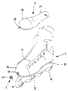
I7 Fig. 1 is a perspective view, partly exploded, of an adjustable skate in
18 accordance with the present invention.
19 Fig. 2 is a side view, partly sectioned, of the adjustable skate in
accordance
2o with the present invention.
21 Fig. 3 is an enlarged view of a front portion of the adjustable skate in
Fig.
22 2, illustrating adjustment of the adjustable skate in accordance with the
present
23 invention.
24 Fig. 4 is a perspective view illustrating adjustment of the adjustable
skate
in accordance with the present invention.
26
2

CA 02414422 2002-12-11
1 Detailed Description of the Preferred Embodiment
2 Referring to Figs. 1 and 2, an adjustable slate in accordance with the
3 present invention generally comprises a boot l, a liner 3, and an adjusting
4 member 2. The boot I includes an upper 11 and a sole 12 that are integrally
molded from rigid plastics. The upper 11 includes a toe cap 16 and a heel
6 portion 17 between which a compartment 13 is defined. A hole 18 is defined
in
7 a front end of the toe cap 16. Ii~Iounted below the sole 12 is a base 15 to
which
8 wheels or rollers 14 are attached. Of course, the rollers 14 can be replaced
with
9 a blade.
The liner 3 is made from rigid plastics and includes a bottom plate 31 on
11 which a foot of a wearer stands. The liner 3 further includes a toe box 32
on a
12 front end of the bottom plate 31. A screw or bolt 33 is formed on a front
end of
13 the toe box 32. The toe box 32 is configured approximately the same as the
toe
14 cap 16, and the bottom plate 31 is slightly smaller than the sole 12. Thus,
the
liner 3 is slidable along a lengthwise direction of the boot 1. A chamber 30
is
16 defined between the toe box 32 and the heel portion 17 of the boot 1 for
17 receiving a foot of a wearer.
18 The adjusting member 2 in this embodiment includes a first end 21
19 engaged in the hole 18 of the toe cap 16 of the boot 1 and a second end 22
having a screw hole 221 for threadedly engaging with the bolt 33 on the toe
21 box 32 of the liner 3. In this embodiment, the first end 21 of the
adjusting
22 member 2 is in the form of a bolt head for engaging with a tool. Thus, as
23 illustrated in Fig. 4, a hexagonal wrench 4 or the file may be engaged with
the
24 first end 21 of the adjusting member 2. The first end 21 of the adjusting
member 2 rotates idly in the hole 18 of the toe cap 16 of the boot 1, yet the
26 position of the liner 30 is changed due to threading engagement between the
3

' CA 02414422 2002-12-11
1 screw hole 221 of the adjusting member 22 and the bolt 33 on the toe box 32
2 of the liner 3, as shown in Fig. 3.
3 In use, as illustrated in Fig. 3, if the wearer feels the chamber 30 is too
4 small for his or her feet, the wearer may turn the adjusting member 2 with a
suitable tool (a hexagonal wrench 4 in Fig. 4 or other suitable tool) to move
6 the liner 3 in the lengthwise direction of the boot 1. The liner 3 is moved
from
7 a position shown by the solid lines to another position shown in phantom
lines.
8 Thus, the overall length of the chamber 30 receiving the foot of the wearer
is
9 increased. On the other hand, if the wearer feels the chamber 30 is too
small
for his or her feet, the wearer may turn the adjusting member 2 in a reverse
11 direction to move the liner 3 to the desired position. The adjusting
procedure is
12 significantly simplified when compared with conventional designs.
13 Although the invention has been explained in relation to its preferred
14 embodiment, it is to be understood that many other possible modifications
and
variations can be made without departing from the scope of the invention as
16 hereinafter claimed.
17

Representative Drawing
A single figure which represents the drawing illustrating the invention.
Administrative Status

2024-08-01:As part of the Next Generation Patents (NGP) transition, the Canadian Patents Database (CPD) now contains a more detailed Event History, which replicates the Event Log of our new back-office solution.

Please note that "Inactive:" events refers to events no longer in use in our new back-office solution.

For a clearer understanding of the status of the application/patent presented on this page, the site Disclaimer , as well as the definitions for Patent , Event History , Maintenance Fee  and Payment History  should be consulted.

Event History

Description Date
Inactive: Dead - No reply to s.30(2) Rules requisition 2006-07-24
Application Not Reinstated by Deadline 2006-07-24
Inactive: IPC from MCD 2006-03-12
Deemed Abandoned - Failure to Respond to Maintenance Fee Notice 2005-12-12
Inactive: Abandoned - No reply to s.30(2) Rules requisition 2005-07-25
Inactive: Abandoned - No reply to s.29 Rules requisition 2005-07-25
Inactive: S.30(2) Rules - Examiner requisition 2005-01-24
Inactive: S.29 Rules - Examiner requisition 2005-01-24
Application Published (Open to Public Inspection) 2004-06-11
Inactive: Cover page published 2004-06-10
Inactive: First IPC assigned 2003-02-25
Inactive: IPC assigned 2003-02-25
Inactive: Filing certificate - RFE (English) 2003-02-03
Filing Requirements Determined Compliant 2003-02-03
Letter Sent 2003-02-03
Application Received - Regular National 2003-02-03
Request for Examination Requirements Determined Compliant 2002-12-11
All Requirements for Examination Determined Compliant 2002-12-11

Abandonment History

Abandonment Date Reason Reinstatement Date
2005-12-12

Maintenance Fee

The last payment was received on 2004-12-03

Note : If the full payment has not been received on or before the date indicated, a further fee may be required which may be one of the following

  • the reinstatement fee;
  • the late payment fee; or
  • additional fee to reverse deemed expiry.

Please refer to the CIPO Patent Fees web page to see all current fee amounts.

Fee History

Fee Type Anniversary Year Due Date Paid Date
Application fee - small 2002-12-11
Request for examination - small 2002-12-11
MF (application, 2nd anniv.) - small 02 2004-12-13 2004-12-03
Owners on Record

Note: Records showing the ownership history in alphabetical order.

Current Owners on Record
MIKE SOO
Past Owners on Record
None
Past Owners that do not appear in the "Owners on Record" listing will appear in other documentation within the application.
Documents

To view selected files, please enter reCAPTCHA code :


To view images, click a link in the Document Description column. To download the documents, select one or more checkboxes in the first column and then click the "Download Selected in PDF format (Zip Archive)" or the "Download Selected as Single PDF" button.

List of published and non-published patent-specific documents on the CPD .

If you have any difficulty accessing content, you can call the Client Service Centre at 1-866-997-1936 or send them an e-mail at CIPO Client Service Centre.


Document
Description 
Date
(yyyy-mm-dd) 
Number of pages   Size of Image (KB) 
Abstract 2002-12-11 1 24
Drawings 2002-12-11 4 70
Description 2002-12-11 4 198
Claims 2002-12-11 2 54
Representative drawing 2003-03-13 1 9
Cover Page 2004-05-14 2 39
Acknowledgement of Request for Examination 2003-02-03 1 173
Filing Certificate (English) 2003-02-03 1 159
Reminder of maintenance fee due 2004-08-12 1 110
Courtesy - Abandonment Letter (R30(2)) 2005-10-03 1 166
Courtesy - Abandonment Letter (R29) 2005-10-03 1 166
Courtesy - Abandonment Letter (Maintenance Fee) 2006-02-06 1 174