Sélection de la langue

Search

Sommaire du brevet 2414422 

Énoncé de désistement de responsabilité concernant l'information provenant de tiers

Une partie des informations de ce site Web a été fournie par des sources externes. Le gouvernement du Canada n'assume aucune responsabilité concernant la précision, l'actualité ou la fiabilité des informations fournies par les sources externes. Les utilisateurs qui désirent employer cette information devraient consulter directement la source des informations. Le contenu fourni par les sources externes n'est pas assujetti aux exigences sur les langues officielles, la protection des renseignements personnels et l'accessibilité.

Disponibilité de l'Abrégé et des Revendications

L'apparition de différences dans le texte et l'image des Revendications et de l'Abrégé dépend du moment auquel le document est publié. Les textes des Revendications et de l'Abrégé sont affichés :

  • lorsque la demande peut être examinée par le public;
  • lorsque le brevet est émis (délivrance).
(12) Demande de brevet: (11) CA 2414422
(54) Titre français: PATIN REGLABLE
(54) Titre anglais: ADJUSTABLE SKATE
Statut: Réputée abandonnée et au-delà du délai pour le rétablissement - en attente de la réponse à l’avis de communication rejetée
Données bibliographiques
Abrégés

Abrégé anglais


An adjustable skate includes a boot and a liner. The boot includes an upper.
and a sole, the upper including a toe cap and a heel portion. The liner is
mounted in the boot and includes a bottom plate slidably mounted on the sole
and a toe box provided on a front end of the bottom plate. A chamber for
receiving a foot of a wearer's foot is defined between the toe box of the
liner
and the heel portion of the boot. A member is formed on the toe box of the
liner. An adjusting member is mounted to the toe cap of the boot and engaged
with the member on the toe box of the liner. The adjusting member and the
member are so configured that rotation of the adjusting member causes the
liner to move along a lengthwise direction of the boot.

Revendications

Note : Les revendications sont présentées dans la langue officielle dans laquelle elles ont été soumises.


What is claimed is:
1. An adjustable skate comprising:
a boot including an upper and a sole, the upper including a toe cap and
a heel portion;
a liner mounted in the boot, the liner including a bottom plate slidably
mounted on the sole and a toe box on a front end of the bottom plate, a
chamber for receiving a foot of a wearer's foot being defined between the
toe box of the liner and the heel portion of the boot, a member being
formed on the toe box of the liner; and
an adjusting member mounted to the toe cap of the boot, the adjusting
member being engaged with the member on the toe box of the liner, the
adjusting member and the member being so configured that rotation of the
adjusting member causes the liner to move along a lengthwise direction of
the boot.
2. The adjustable skate as claimed in claim 1, wherein the member on the toe
box of the liner is a bolt.
3. The adjustable skate as claimed in claim 2, wherein the adjusting member
includes an end having a screw hole for threadedly engaging with the bolt
on the toe box of the liner.
4. The adjustable skate as claimed in claim 3, wherein the toe cap of the boot
includes a hole in a front end thereof, the adjusting member including
another end that is received in the hole of the toe cap, said another end of
the adjusting member rotating idly when the adjusting member is turned.
5. The adjusting skate as claimed in claim 1, wherein the adjusting member
includes an end that is drivable by a tool.
5

6. The adjustable skate as claimed in claim 4, wherein said another end of the
adjusting member is drivable by a tool.
7. The adjustable skate as claimed in claim 1, wherein the liner is made from
rigid plastics.

Description

Note : Les descriptions sont présentées dans la langue officielle dans laquelle elles ont été soumises.

CA 02414422 2002-12-11
1 ADJUSTABLE SKATE
2 Background of the Invention
3 1. Field of the Invention
4 The present invention relates to an adjustable skate. In particular, the
present invention relates to an adjustable skate for adjusting a length of a
6 chamber in the boot of the adjustable skate according to different foot
lengths
7 of different wearers.
8 2. Description of the Related Art
9 Skates, whether with wheels or a blade, axe popular among young people.
Many skates are adjustable in length and/or width to suit different foot sizes
of
11 various wearers. Nevertheless, the adjusting mechanisms of the skates are
12 complicated and thus costly. Further, the adjusting procedures for the
adjusting
13 mechanisms are troublesome and time-consuming, as they include detachment
14 of bolts and screws before adjustment as well as reassembling of the bolts
and
screws after adjustment. It is, therefore, a long and unfulfilled need in a
simple
16 adjusting device for the skates without time-consuming procedure for
17 adjustment.
18 Summary of the Invention
19 An object of the present invention is to provide an adjustable skate having
a bladder for adjusting a length of a chamber in the boot of the adjustable
skate
21 according to different foot lengths of different wearers.
22 An adjustable skate in accordance with the present invention includes a
23 boot and a liner. The boot includes an upper and a sole, the upper
including a
24 toe cap and a heel portion. The liner is mounted in the boot and includes a
bottom plate slidably mounted on the sole and a toe box provided on a front
26 end of the bottom plate. A chamber for receiving a foot of a wearer's foot
is
I

CA 02414422 2002-12-11
1 defined between the toe box of the liner and the heel portion of the boot. A
2 member is formed on the toe box of the liner.
3 An adjusting member is mounted to the toe cap of the boot and engaged
4 with the member on the toe box of the liner. The adjusting member and the
member are so configured that rotation of the adjusting member causes the
6 liner to move along a lengthwise direction of the boot.
7 In an embodiment of the invention, the member on the toe box of the liner
8 is a bolt, and the adjusting member includes an end having a screw hole for
9 threadedly engaging with the bolt on the toe box of the liner. The toe cap
of the
l0 boot includes a hole in a front end thereof. The other end of the adjusting
11 member is received in the hole of the toe cap and drivable by a tool. The
other
12 end of the adjusting member rotates idly when the adjusting member is
turned.
13 Other objects, advantages, and novel features of the invention will become
14 more apparent from the following detailed description when taken in
conjunction with the accompanying drawings.
16 Brief Description of the Drawings
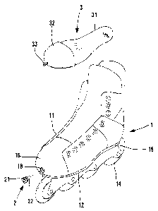
I7 Fig. 1 is a perspective view, partly exploded, of an adjustable skate in
18 accordance with the present invention.
19 Fig. 2 is a side view, partly sectioned, of the adjustable skate in
accordance
2o with the present invention.
21 Fig. 3 is an enlarged view of a front portion of the adjustable skate in
Fig.
22 2, illustrating adjustment of the adjustable skate in accordance with the
present
23 invention.
24 Fig. 4 is a perspective view illustrating adjustment of the adjustable
skate
in accordance with the present invention.
26
2

CA 02414422 2002-12-11
1 Detailed Description of the Preferred Embodiment
2 Referring to Figs. 1 and 2, an adjustable slate in accordance with the
3 present invention generally comprises a boot l, a liner 3, and an adjusting
4 member 2. The boot I includes an upper 11 and a sole 12 that are integrally
molded from rigid plastics. The upper 11 includes a toe cap 16 and a heel
6 portion 17 between which a compartment 13 is defined. A hole 18 is defined
in
7 a front end of the toe cap 16. Ii~Iounted below the sole 12 is a base 15 to
which
8 wheels or rollers 14 are attached. Of course, the rollers 14 can be replaced
with
9 a blade.
The liner 3 is made from rigid plastics and includes a bottom plate 31 on
11 which a foot of a wearer stands. The liner 3 further includes a toe box 32
on a
12 front end of the bottom plate 31. A screw or bolt 33 is formed on a front
end of
13 the toe box 32. The toe box 32 is configured approximately the same as the
toe
14 cap 16, and the bottom plate 31 is slightly smaller than the sole 12. Thus,
the
liner 3 is slidable along a lengthwise direction of the boot 1. A chamber 30
is
16 defined between the toe box 32 and the heel portion 17 of the boot 1 for
17 receiving a foot of a wearer.
18 The adjusting member 2 in this embodiment includes a first end 21
19 engaged in the hole 18 of the toe cap 16 of the boot 1 and a second end 22
having a screw hole 221 for threadedly engaging with the bolt 33 on the toe
21 box 32 of the liner 3. In this embodiment, the first end 21 of the
adjusting
22 member 2 is in the form of a bolt head for engaging with a tool. Thus, as
23 illustrated in Fig. 4, a hexagonal wrench 4 or the file may be engaged with
the
24 first end 21 of the adjusting member 2. The first end 21 of the adjusting
member 2 rotates idly in the hole 18 of the toe cap 16 of the boot 1, yet the
26 position of the liner 30 is changed due to threading engagement between the
3

' CA 02414422 2002-12-11
1 screw hole 221 of the adjusting member 22 and the bolt 33 on the toe box 32
2 of the liner 3, as shown in Fig. 3.
3 In use, as illustrated in Fig. 3, if the wearer feels the chamber 30 is too
4 small for his or her feet, the wearer may turn the adjusting member 2 with a
suitable tool (a hexagonal wrench 4 in Fig. 4 or other suitable tool) to move
6 the liner 3 in the lengthwise direction of the boot 1. The liner 3 is moved
from
7 a position shown by the solid lines to another position shown in phantom
lines.
8 Thus, the overall length of the chamber 30 receiving the foot of the wearer
is
9 increased. On the other hand, if the wearer feels the chamber 30 is too
small
for his or her feet, the wearer may turn the adjusting member 2 in a reverse
11 direction to move the liner 3 to the desired position. The adjusting
procedure is
12 significantly simplified when compared with conventional designs.
13 Although the invention has been explained in relation to its preferred
14 embodiment, it is to be understood that many other possible modifications
and
variations can be made without departing from the scope of the invention as
16 hereinafter claimed.
17

Dessin représentatif
Une figure unique qui représente un dessin illustrant l'invention.
États administratifs

2024-08-01 : Dans le cadre de la transition vers les Brevets de nouvelle génération (BNG), la base de données sur les brevets canadiens (BDBC) contient désormais un Historique d'événement plus détaillé, qui reproduit le Journal des événements de notre nouvelle solution interne.

Veuillez noter que les événements débutant par « Inactive : » se réfèrent à des événements qui ne sont plus utilisés dans notre nouvelle solution interne.

Pour une meilleure compréhension de l'état de la demande ou brevet qui figure sur cette page, la rubrique Mise en garde , et les descriptions de Brevet , Historique d'événement , Taxes périodiques et Historique des paiements devraient être consultées.

Historique d'événement

Description Date
Inactive : Morte - Aucune rép. dem. par.30(2) Règles 2006-07-24
Demande non rétablie avant l'échéance 2006-07-24
Inactive : CIB de MCD 2006-03-12
Réputée abandonnée - omission de répondre à un avis sur les taxes pour le maintien en état 2005-12-12
Inactive : Abandon. - Aucune rép dem par.30(2) Règles 2005-07-25
Inactive : Abandon. - Aucune rép. dem. art.29 Règles 2005-07-25
Inactive : Dem. de l'examinateur par.30(2) Règles 2005-01-24
Inactive : Dem. de l'examinateur art.29 Règles 2005-01-24
Demande publiée (accessible au public) 2004-06-11
Inactive : Page couverture publiée 2004-06-10
Inactive : CIB attribuée 2003-02-25
Inactive : CIB en 1re position 2003-02-25
Inactive : Certificat de dépôt - RE (Anglais) 2003-02-03
Lettre envoyée 2003-02-03
Demande reçue - nationale ordinaire 2003-02-03
Exigences pour une requête d'examen - jugée conforme 2002-12-11
Toutes les exigences pour l'examen - jugée conforme 2002-12-11

Historique d'abandonnement

Date d'abandonnement Raison Date de rétablissement
2005-12-12

Taxes périodiques

Le dernier paiement a été reçu le 2004-12-03

Avis : Si le paiement en totalité n'a pas été reçu au plus tard à la date indiquée, une taxe supplémentaire peut être imposée, soit une des taxes suivantes :

  • taxe de rétablissement ;
  • taxe pour paiement en souffrance ; ou
  • taxe additionnelle pour le renversement d'une péremption réputée.

Les taxes sur les brevets sont ajustées au 1er janvier de chaque année. Les montants ci-dessus sont les montants actuels s'ils sont reçus au plus tard le 31 décembre de l'année en cours.
Veuillez vous référer à la page web des taxes sur les brevets de l'OPIC pour voir tous les montants actuels des taxes.

Historique des taxes

Type de taxes Anniversaire Échéance Date payée
Requête d'examen - petite 2002-12-11
Taxe pour le dépôt - petite 2002-12-11
TM (demande, 2e anniv.) - petite 02 2004-12-13 2004-12-03
Titulaires au dossier

Les titulaires actuels et antérieures au dossier sont affichés en ordre alphabétique.

Titulaires actuels au dossier
MIKE SOO
Titulaires antérieures au dossier
S.O.
Les propriétaires antérieurs qui ne figurent pas dans la liste des « Propriétaires au dossier » apparaîtront dans d'autres documents au dossier.
Documents

Pour visionner les fichiers sélectionnés, entrer le code reCAPTCHA :


Pour visualiser une image, cliquer sur un lien dans la colonne description du document. Pour télécharger l'image (les images), cliquer l'une ou plusieurs cases à cocher dans la première colonne et ensuite cliquer sur le bouton "Télécharger sélection en format PDF (archive Zip)" ou le bouton "Télécharger sélection (en un fichier PDF fusionné)".

Liste des documents de brevet publiés et non publiés sur la BDBC .

Si vous avez des difficultés à accéder au contenu, veuillez communiquer avec le Centre de services à la clientèle au 1-866-997-1936, ou envoyer un courriel au Centre de service à la clientèle de l'OPIC.


Description du
Document 
Date
(aaaa-mm-jj) 
Nombre de pages   Taille de l'image (Ko) 
Abrégé 2002-12-10 1 24
Dessins 2002-12-10 4 70
Description 2002-12-10 4 198
Revendications 2002-12-10 2 54
Dessin représentatif 2003-03-12 1 9
Accusé de réception de la requête d'examen 2003-02-02 1 173
Certificat de dépôt (anglais) 2003-02-02 1 159
Rappel de taxe de maintien due 2004-08-11 1 110
Courtoisie - Lettre d'abandon (R30(2)) 2005-10-02 1 166
Courtoisie - Lettre d'abandon (R29) 2005-10-02 1 166
Courtoisie - Lettre d'abandon (taxe de maintien en état) 2006-02-05 1 174