Note: Descriptions are shown in the official language in which they were submitted.
CA 02414567 2002-12-30
WO 02/06035 PCT/USO1/21720
BLOW-MOLDED CONTAINER AND CLOSURE, AND
METHOD AND APPARATUS FOR MAKING SAME
Field of the Invention
The present invention relates to a blow-molded plastic container and a
corresponding closure produced by a combination of blow molding/compression
molding techniques, and more particularly, the present invention relates to a
method
and apparatus for the simultaneous manufacture of a blow molded container and
a
partially blow-molded, partially compression molded closure within the same
blow
mold.
Background of the Invention
Various consumer products, such as food products, are packaged for sale in
blow-molded plastic containers sealed with a closure. Typically, the
containers are
mass produced in high speed blow-molding machines, and the closures, such as
caps
and lids, are manufactured separately from the containers in injection molds.
The
separate manufacture of the containers and closures has a significantly impact
on the
overall cost of mass producing such a package. Such increased costs include
manufacturing, tooling and material costs.
Another disadvantage of manufacturing containers and closures utilizing
different molding processes is that such processes require the use of
different plastic
materials which results in the containers being made of one type of plastic
material and
the closures being made of another. Such a package complicates and increases
the
cost of recycling the containers and closures and does not readily permit
precise color
matching between the container and closure. Thus, the separate manufacture of
the
container and closure also has a negative impact on the aesthetic appearance
of the
package and its ability to be readily recycled.
To overcome these problems, the assignee of the present application has
previously developed and disclosed in International Application No.
PCT/US97/03153, published as International Publication Number WO 97/32791 on
September 12, 1997, a method for compression molding a closure in the flash
material
of an extrusion blow mold. To this end, a parison is extruded within a blow
mold
CA 02414567 2002-12-30
WO 02/06035 PCT/USO1/21720
having a container body cavity and a lid cavity. The parison is blown in the
container
body cavity to form the container body and is compressed in the lid cavity to
form a
compression molded lid for the blow molded container. Thus, the lid is formed
in the
flash material which would otherwise be removed from the container and
recycled as
scrap material. The entire package can be readily recycled and can be a
consistent
colorthroughout.
Other examples of forming articles in the flash material compressed in blow
molds include U.S. Patent Nos.: 4,082,827 issued to Chlystun; 5,165,558 issued
to
Cargile; 3,359,602 issued to Bailey; 3,369,690 issued to Hayes; 3,679,785
issued to
Dike; 5,275,780 to Robinson; and 3,983,199 issued to Uhlig. The Chlystun
patent
discloses compression molding an integral pull tab; the Cargile patent
discloses
compression molding a breakaway measuring cup; and the Bailey, Hayes, Dike,
Robinson and Uhlig patents disclose compression molding an integral handle.
Other U.S. patents disclose the formation of blown closures within the
container body cavity of a blow mold. To this end, the container body and
closure are
blown as a single intermediate body within a blow mold cavity. The blown
intermediate article is then severed and trimmed to form a separate container
body and
closure. See for instance, U.S. Patent Nos.: 5,553,732 and 5,762,859 issued to
Kani;
5,044,923 and 5,213,753 issued to Przytulla; 3,409,710 issued to Klygisis; and
5,865,338 issued to Conn. Also see U.S. Patent Nos.: 5,106,569 issued to
Rathman
et al.; 4,382,058 and 4,453,911 issued to Watson et al.; and 4,486,164 and
4,486,379
issued to Wilkie et al. for examples of blow molded tool box-shaped
containers, or
cases, having opposed blow-molded tub-shaped portions integrally connected by
a
compression molded hinge.
In addition to the need for a cost-effective, readily recyclable and aesthetic
container and closure combination and a method and apparatus for making same,
there is also a specific need for a substantially tub-shaped container having
an upper
rim and a novel closure, or lid, for sealing the container. Such a container
may be
used as a multi-purpose package, for instance, in club or warehouse stores for
the sale
of powders such as drink powders, candy or any other product capable of being
sold
2
CA 02414567 2002-12-30
WO 02/06035 PCT/USO1/21720
in tub-shaped containers. The upper rim of such a container provides a wide
opening
into the container and is sealed with a relatively large flat lid which spans
the opening
and engages the rim. Typically, the central most portion of such a lid will
warp and
otherwise provide an unaesthetic appearance.
Although the above referenced container and closure combinations and
methods and apparatus for the manufacture thereof may function satisfactorily
for
their intended purposes, there is a need for a novel method and apparatus for
the cost-
effective manufacture of a container and closure combination. In addition,
there is
also a specific need for a novel container and closure combination which
includes a
tub-shaped blow molded container and a reinforced lid. The lid should have
improved
rigidity and definition to prevent warpage and should provide an aesthetically
pleasing
package. The container and lid should be capable of efficient and simultaneous
manufacture in the same blow mold, should be readily recyclable, and should
have
substantially flawless color matching.
Objects of the Invention
With the foregoing in mind, a primary object of the present invention is to
provide a novel method for simultaneously forming a plastic container and
associated
closure from a single extruded parison in the same blow mold utilizing a
combination
of blow molding and compression molding techniques.
Another object of the present invention is to a provide a closure, or lid,
with
increased rigidity and definition so that the lid can be utilized in
connection with a
wide-mouth tub-shaped container without undergoing warpage and can provide an
aesthetically pleasing appearance.
A further object of the present invention is to provide a novel method and
apparatus for manufacturing a reinforced closure, or lid, in a blow mold.
A still further object of the present invention is to provide apparatus which
enables the formation of various indentations and undercuts to be formed in a
blown
container and/or closure and which enables ready ejection of the container and
a
reinforced closure from the mold.
3
CA 02414567 2002-12-30
WO 02/06035 PCT/USO1/21720
Summary of the Invention
More specifically, the present invention provides a method of manufacturing a
plastic container and associated closure in which a parison is extruded within
an open
set of mold blocks. The mold blocks, when closed, cooperate to form a
container
forming cavity and a separate closure forming cavity through which the parison
extends. The parison located in the container forming cavity is blown to form
a
container body while a portion of the parison located in the closure forming
cavity is
separately blown to form at least a part of a closure. A remaining portion of
the
parison located in the closure forming cavity is compression molded to form a
remaining part of the closure which extends integrally from the blow molded
part of
the closure. Preferably, blow molding of the container body, blow molding of
the part
of the closure, and compression molding of the remaining part of the closure
occur
substantially simultaneously. The present invention also provides a container
and
closure combination made by the above described process.
1 S According to another aspect of the present invention, a novel apparatus
for
manufacturing a container and associated closure is provided. The apparatus
includes
a set of mold blocks moveable from an open position to a closed position to
capture
an extruded parison therein and moveable from the closed position to the open
position for releasing a container body and closure therefrom. The mold
blocks, when
closed, cooperate to provide a blow molded container forming cavity and a
separate
closure forming cavity which includes a blow-molding section and a compression
molding section. A first blow pin is extendable into the container forming
cavity for
forming a blow-molded container body therein, and a second blow pin is
extendable
into the blow molding section of the closure forming cavity to blow a portion
of the
closure. The compression molding section forms a remaining integral
compression
molded portion of the closure. Preferably, the mold blocks and first and
second blow
pins are operable to substantially simultaneously form the blow molded
container body
and partially blow molded, partially compression molded closure.
According to yet another aspect of the present invention, a novel container
and reinforced lid combination is provided. The container has an extrusion
blow
4
CA 02414567 2002-12-30
WO 02/06035 PCT/USO1/21720
molded body with an upper rim. The lid has a hollow central blow molded
portion
and a peripheral compression molded portion extending outwardly and integrally
from
the hollow central blow molded portion. The peripheral compression molded
portion
of the lid is engageable with the upper rim of the container body to secure
the lid to
the container, and the hollow central blow molded portion of the lid
reinforces the lid
structure to increase rigidity and definition and prevent warpage.
Brief Description of the Drawings
The foregoing and other objects, features and advantages of the present
invention should become apparent from the following description when taken in
conjunction with the accompanying drawings, in which:
FIG. 1 is a perspective view of a container and lid embodying the present
invention;
FIG. 2 is a cross sectional view of a blow mold and container formed therein
according to the present invention;
FIG. 3 is a cross-sectional view of the blow mold, container and lid of FIG. 2
taken along line 3--3 ;
FIG. 4 is a partial cross-sectional view of the container and lid of FIG. 1
illustrating the pivoting connection between the container and lid; and
FIG. 5 is a cross-sectional view of the connection illustrated in FIG. 4 taken
along line 5--5.
Detailed Description of the Preferred Container/Closure Combination
One aspect of the present invention is a preferred container and closure
combination 10 as best illustrated in FIGs. 1 and 4. The combination is
preferably
made by the method and apparatus of the present invention as will be
discussed.
Before turning to a detailed description of the method and apparatus of the
present
invention, a discussion of the structure of the preferred container/closure 10
is
provided.
5
CA 02414567 2002-12-30
WO 02/06035 PCT/USO1/21720
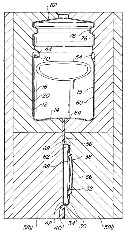
The combination 10 includes a plastic extrusion blow-molded container body
12 provided in a substantially tub-shaped configuration. As illustrated, the
body 12 is
substantially rectangular having a base 14 and an integral upstanding sidewall
16
including front, rear, right and left sidewall sections, 18, 20, 22 and 24,
respectively.
The container body 12 has a large top opening 26 which is defined by a rim 28
formed
by the upper terminating edge of the sidewall 16. Such a tub-shaped container
can be
utilized to package various products including scoop-able food products
provided in
powder form, such as, chocolate drink mixes. A sheet-like tamper-indication
covering
(not shown), such as wax paper, foil, or the like, can be sealed to the rim 28
after
initial filling of the container body 12 to initially seal the opening 26,
maintain the
contents in a sterile environment, and provide indication of tampering.
Although a
specific container body configuration has been described and illustrated,
various other
container body structures can be utilized in accordance with the present
invention.
A lid 30 having a novel reinforced structure, as best illustrated in FIG. 4,.
is
utilized as a closure or cap for the container body 12. The lid 30 is
reinforced to resist
warpage which would otherwise occur. in a typical flat lid applied to and
spanning
across the relatively large sized opening 26 of the container body 12. The
novel
structure of lid 30 includes a hollow central section 32 and a substantially
solid
peripheral section 34 extending integrally and radially outward from the
hollow central
section 32. The hollow central section 32 is formed by blow molding a portion
of an
extruded parison in a blow mold, preferably the same blow mold utilized to
form the
blown container body 12. The solid peripheral section 34 is formed by
compression
molding a portion of the extruded parison in the blow mold. Thus, as will be
discussed in detail, the same extruded parison can be utilized in the same
blow mold to
form the container body 12 and lid 30.
The compression molded peripheral section 34 of lid 30 provides a peripheral
lip 36 utilized to engage the rim 28 of the container body 12. The blow-molded
hollow central section 32 of the lid 30 reinforces the lid 30, prevents the
lid 30 from
warping, and provides an aesthetically pleasing appearance. In addition, a
brand
name, logo, or the like (not shown) can be blown into the upward facing side
38 of
6
CA 02414567 2002-12-30
WO 02/06035 PCT/USO1/21720
the lid to increase its aesthetic appeal. The lid 30 is made from the same
material as
the container body 12, and therefore, is readily recyclable with the container
body 12
and is substantially the exact same color as the container body 12.
The preferred embodiment, as illustrated, permits the lid 30 to pivot relative
to
the container body 12 between open and closed positions. To this end, a
compression
molded hinge connection flap 40 is formed in the compression molded peripheral
section 34 of the lid 30. The hinge connection flap 40 extends from the lip 36
and has
a pair of oppositely extending lateral projections 42 as best illustrated in
FIG. 5. The
rear sidewall section 20 of the container body 12 is formed with an inwardly
extending
recess 44 for receiving the hinge connection flap 40. A pair of depressions 46
are
formed in the sidewall sections 48 of the recess 44 and extend substantially
parallel to
the rear sidewall section 20 of the container body 12. To install the lid 30
on the
container body 12, the projections 42 of the hinge connection flap 40 are
inserted into
the depressions 46 formed in the recess 44 of the container sidewall 16. The
projections 42 are captured within the depressions 46 and permit the lid 30 to
pivot
thereabout.
The lid 30 of the preferred embodiment is adapted to be snap fit to the rim 28
of the container body 12. To this end, preferably the rim 28 has an outwardly
extending peripheral bead 50 which frictionally engages a set of locking beads
52
extending inwardly from the lip 36 of the lid 30 to maintain the lid 30 in a
closed
condition sealing the top opening 26 of the container body 12. See FIG. 4. To
enable
ready opening of the lid 30, the front sidewall section 18 of the container
body 12 is
provided with a recess 54 adjacent the rim 28 to permit a person's finger to
engage
beneath the lip 36 of the lid 30 and to lift upwardly on the lid 30 removing
the lid 30
from the rim 28 of the container body 12.
By way of example, and not by way of limitation, the container body 12 can be
about 6.5 inches in height from the base 14 to the rim 28, about 8.5 inches in
length
from the right to the left sidewall section, 22 and 24, and about five inches
in width
from the front to the rear sidewall section, 18 and 20. The opening 26 can be
about 5
by 8.5 inches, and the container body 12 can contain approximately 100 ounces
of a
7
CA 02414567 2002-12-30
WO 02/06035 PCT/USO1/21720
product. The lid 30 can be about 5 by 8.5 inches, and the dimensions of the
hollow
central section 32 can be about 3.5 by 6.5 inches with a maximum thickness of
about a
half inch. The combination 10 can be made of any thermoplastic material, for
example, HDPE or Polypropylene. The above referenced material and dimensions
are
provided as examples only, and any desired materials and dimensions can be
utilized in
accordance with the present invention.
Detailed Description of the Preferred Method
As previously stated, the above referenced container and closure combination
is formed primarily by extrusion blow molding techniques and partly by
10 compression molding techniques. As well known in the art of extrusion blow
molding, a pair of mold halves are initially positioned in an open position to
receive an
extruded tube of molten plastic, or parison, and are then closed about the
parison so
that the parison can be blown within the cavity formed by the blow mold.
Typically,
the sections of the parison above and below the blown body form so called
flash
material which is trimmed from the blown body and recycled as scrap material.
According to the present invention, a portion 56 of what would be the flash
material is utilized to form a closure 30 for the container body 12. Thus, the
container
body 12 and closure 30 are simultaneously formed in the same mold 58 from the
same
parison. This provides a package which is made of a common material that can
be
readily recycled and that is a uniform color.
One novel aspect of the present invention is that the closure 30 is formed by
a
combination of blow molding and compression molding techniques. To this end, a
portion of the parison is blown to form a hollow part 32 of the closure 30 and
another
portion of the parison is compressed to form a substantially solid part 34 of
the
closure 30. Thus, the closure 30 includes a hollow section 32 to rigidify the
closure
and prevent warpage, and a solid section 34 to provide a means of
cooperatively
engaging the rim 28 of the container body 12.
The method according to the present invention utilizes a pair of mold halves
58_a and 58b_ which cooperate to provide a container body forming cavity 60
and a
8
CA 02414567 2002-12-30
WO 02/06035 PCT/USO1/21720
closure forming cavity 62 best illustrated in FIGs. 2 and 3. These cavities,
60 and 62,
are spaced apart in the mold 58 and receive different sections of the same
parison.
For example, the parison is positioned in the mold 58 such that a proximal end
of the
parison is used to form the container body 12 and a distal end of the parison
is used to
form the closure 30. Thus, as the blown and compressed parison is removed from
the
mold 58, the closure 30 is formed in a tail flash area 64 which extends from
the base
14 of the blown container body 12. See FIG. 3.
The closure forming cavity 62 includes a central blow molding cavity 66 and a
peripheral compression molding cavity 68. Thus, a portion of the parison is
blown as
a surrounding portion of the parison is compressed. Therefore, the method of
the
present invention includes the primary steps of (i) capturing an extruded
parison
within a pair of mold blocks, 58a and 58b_; (ii) blow molding a portion of the
parison
in a container forming cavity 60 to form a blow molded container body 12;
(iii)
separately blow molding another portion of the parison in a closure forming
cavity 62;
and (iv) compression molding a portion of the parison in the closure forming
cavity 62
to produce a partially blow molded, partially compression molded closure 30
for the
container body 12. Preferably, all of the above stated method steps are
accomplished
substantially simultaneously in high speed automated equipment.
According to the preferred method, various undercuts can be formed in the
container body, such as, the depressions 46 formed in the recess 44 in the
container
body 12 as illustrated in FIG. 5. Typically, a blow mold cannot have structure
which
prevents a blow molded body to be released from the mold cavity. For instance,
the
formation of the depressions 46 in the container body 12 requires mold
structure that
extends laterally into the cavity 60 to from the depressions 46 and that would
block
the removal of the container body 12 form the mold since the container body 12
is
blown behind and around the structure. However, the present invention
overcomes
this problem by utilizing a pair of extendableJretractable pins 70 which
extend as the
parison is blown and retract slightly before the blown container body 12 is
released
from the mold 58. Thus, the pins 70 form the depressions 46 in the container
body 12
and are retractable to enable ready release of the container body 12 from the
mold 58.
9
CA 02414567 2002-12-30
WO 02/06035 PCT/USO1/21720
Preferably, the pins 70 are extended by cylinders (not shown) which are
precisely
controlled to extend and retract at predetermined times during the blow
molding
cycle.
The method also includes a novel manner of releasing, or ejecting, the
S container body 12, closure 30, and flash 64 from the mold 58. The lid 30
tends to
stick to the mold 58 since the lid 30 is relatively large and includes blow
molded and
compression molded portions, 32 and 34. The present invention utilizes an
ejector
plate 72 to force the lid 30 out of the mold 58. As best illustrated in FIG.
2, the
ejector plate 72 is located in mold half 58a adjacent the closure forming
cavity 62 and
is extended into the closure forming cavity 62 after the mold blocks 58_a and
58b open
to eject the closure 30 from the mold 58 thereby releasing the closure 30 with
the
container body 12 and adjacent flash material 64. Preferably, the ejector
plate 72
includes a pair of cylinders 72a and 72b which are extended at precisely
controlled
predetermined times during the blow molding cycle.
A further step in the preferred method is to trim the scrap material 74 from
the
container body 12 and lid 30. To this end, the tail flash 64 is cut from the
base 14 of
the container 12 and trimmed away from the lid 30 formed in the tail flash 64.
Preferably as illustrated in FIG.3, the container body is blown with a false
dome 76
which must also be severed from the container body 12. The blown false dome 76
includes a groove 78 used by trimming equipment to spin the container body 12
and
false dome 76 relative to a knife in the trimmer. Thus, the knife severs the
false dome
76 from the container body 12 and provides the container body 12 with a smooth
inwardly extending lip 80 to which wax paper, or the like, can be bonded to
initially
seal the container body 12 after filling.
A final step includes assembling the lid 30 to the container body 12 after
they
have been completely separated during trimming. The projections 42 on the
hinge
connection flap 40 of the lid 30 are inserted into the depressions 46 formed
in the
container body 12 to connect the lid 30 to the container body 12. The lid 30
is
pivoted relative to the container body 12 and snap fit onto the rim 28.
CA 02414567 2002-12-30
WO 02/06035 PCT/USO1/21720
Detailed Description of the Preferred Apparatus
The primary component of the apparatus according to the present invention
utilized to manufacture the container and closure combination of the present
invention
are the mold blocks 58_a and 58b_ as previously discussed. The multi-part mold
58
must be capable of opening and closing relative to an extruded parison to
capture the
parison therein. In addition, the mold 58 must define a container body forming
cavity
60 and a separate closure forming cavity 62 a spaced distance from the
container body
forming cavity 60.
As best illustrated in FIG. 3, the container body forming cavity 60 defines
the
shape of the container body 12 and includes a false blow dome cavity area 82.
The
formation of a false dome 76 enables ready spin trimming of scrap material
from the
top of the container body 12 so that a smooth inwardly extending lip 80 can be
provided on the rim 28 of the trimmed container body 12. The walls of the
container
body forming cavity 60 also include extendable/retractable pins 70 which
enable
undercuts to be formed in the container body 12 in a manner permitting ready
release
of the container body 12 from the mold 58. The extension and retraction of the
pins
70 are precisely controlled and linked to the blow molding cycle.
As best illustrated in FIG. 3, the closure forming portion 62 includes a blow
molding area 66 and a compression molding area 68. The blow molding area 66 is
centrally located and is surrounded by the compression molding area 68. Thus,
a
central portion 32 of the lid 30 is formed by blow molding, and a peripheral
portion 34
of the lid 30 is formed by compression molding. Preferably, the compression
molding
area 68 is utilized to form a hinge connection flap 40 utilized to pivotally
connect the
lid 30 to the container body 12. The closure forming cavity 62 also includes
an
ejector plate 72 which extends into the cavity 62 to cause the forced release
of the lid
from the mold 58. The ejector plate 72 is set to operate at a precise
predetermined
time in the blow molding cycle.
The apparatus also includes a pair of blow pins which are inserted into the
parison to inflate the parison. A first blow pin (not shown) is utilized to
inflate the
30 container body 12 and extends into a part of the parison which forms the
blown false
11
CA 02414567 2002-12-30
WO 02/06035 PCT/USO1/21720
dome 76. A second blow pin 84 is utilized to inflate the blow molded portion
32 of
the closure 30. Preferably, the blow pin 84 is inserted through the cavity
wall adjacent
the location of the ejector plate 72. In addition, the aperture 86 formed in
the lid 30
by the blow pin 84 is preferably formed on the underside 88 of the lid 30.
Thus, as
illustrated in FIG. 2, a blow cylinder 90 is located between the pair of
ejector plate
cylinders, 72_a and 72b, which also extend toward the underside 88 of the lid
30.
The apparatus of the present invention also includes a timing mechanism (not
shown) to precisely control the operation of the mold and blow pins. To this
end, the
blow pins are controlled to simultaneously blow the lid 30 and container body
12. In
addition, the retractable pins 70 utilized to form the undercuts in the
container body
12 are extended during inflation of the container body 12. As the mold 58
opens to
release the container body 12 and lid 30, the pins 70 are retracted and the
ejector plate
72 is extended into the lid forming cavity 62.
Thus, the described container and closure combination, method of making the
combination, and apparatus for making the combination provide a unique and
cost-
effective package which can be entirely manufacture in a blow mold utilizing a
single
extruded parison. Preferably, the blow molded container has a tub-shape, and
the lid
has a novel reinforced structure which resists warpage. The lid can be
provided such
that it pivots relative to the container body, and the container body can be
formed
with various undercut areas. In addition, the container body and lid are
readily
released from the mold utilizing an ejector plate.
While a preferred container and closure combination, method of making the
combination, and apparatus for making the combination have been described in
detail,
various modifications, alterations, and changes may be made without departing
from
the spirit and scope of the present invention as defined in the appended
claims.
12