Language selection

Search

Patent 2414645 Summary

Third-party information liability

Some of the information on this Web page has been provided by external sources. The Government of Canada is not responsible for the accuracy, reliability or currency of the information supplied by external sources. Users wishing to rely upon this information should consult directly with the source of the information. Content provided by external sources is not subject to official languages, privacy and accessibility requirements.

Claims and Abstract availability

Any discrepancies in the text and image of the Claims and Abstract are due to differing posting times. Text of the Claims and Abstract are posted:

  • At the time the application is open to public inspection;
  • At the time of issue of the patent (grant).
(12) Patent: (11) CA 2414645
(54) English Title: METHOD FOR DETERMINING THE ANGLE OF A ROTOR BLADE PERTAINING TO A WIND ENERGY INSTALLATION
(54) French Title: PROCEDE POUR DETERMINER L'ANGLE D'UNE PALE DE ROTOR D'UNE INSTALLATION A ENERGIE EOLIENNE
Status: Expired
Bibliographic Data
(51) International Patent Classification (IPC):
  • F03D 7/02 (2006.01)
  • B64C 27/00 (2006.01)
  • B64C 27/02 (2006.01)
  • F03D 7/00 (2006.01)
(72) Inventors :
  • WOBBEN, ALOYS (Germany)
(73) Owners :
  • WOBBEN, ALOYS (Germany)
(71) Applicants :
  • WOBBEN, ALOYS (Germany)
(74) Agent: OYEN WIGGS GREEN & MUTALA LLP
(74) Associate agent:
(45) Issued: 2007-02-20
(86) PCT Filing Date: 2001-05-05
(87) Open to Public Inspection: 2002-12-30
Examination requested: 2002-12-30
Availability of licence: N/A
(25) Language of filing: English

Patent Cooperation Treaty (PCT): Yes
(86) PCT Filing Number: PCT/EP2001/005103
(87) International Publication Number: WO2002/002936
(85) National Entry: 2002-12-30

(30) Application Priority Data:
Application No. Country/Territory Date
100 32 314.6 Germany 2000-07-04

Abstracts

English Abstract


In pitch-regulated wind power installations the angles of the rotor
blades can be adjusted synchronously (standard construction) or
independently of each other. The construction for adjustment
independently of each other is described in patent application DE 197 31
918. That design can also be referred to as on-line individual blade
adjustment. Both in the standard construction and also in the arrangement
involving on-line individual blade adjustment, it is important that an initial
blade angle, for example feathered position or maximum blade angle, can
be set with a sufficient degree of accuracy.

The object of the present invention is to avoid the above-discussed
disadvantages so that it is possible to more quickly ascertain the correct
blade angle and the results are more accurate than hitherto and also
measurement from the ground is possible, while the entire measuring
equipment should be easily disconnected so that simple transportation of
the measuring equipment is also possible.

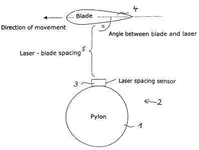
A method of accurately determining the angle of a rotor blade of a
wind power installation, wherein the spacing between the rotor blade and
the pylon of the wind power installation is ascertained, the ascertained data
are processed in a computer, and the angle (a) between a rotor blade and
the spacing measuring device is determined from the stored values.


French Abstract

L'invention concerne un procédé permettant de déterminer avec exactitude l'angle d'une pale de rotor (4) d'une installation à énergie éolienne (2), selon lequel l'écart (5) entre la pale de rotor et la pointe (1) de l'installation d'énergie éolienne est déterminé. Les données obtenues sont traitées dans un ordinateur et l'angle ( alpha ) compris entre la pale de rotor et le dispositif de mesure d'écart est déterminé sur la base des valeurs mémorisées.

Claims

Note: Claims are shown in the official language in which they were submitted.


CLAIMS

1. A method of accurately determining the pitch angle of at least one rotor
blade of a wind power installation, the method comprising the steps of:

a. along at least a portion of the surface of the rotor blade, measuring
a spacing between each of a plurality of surface points of the rotor
blade and a space-measuring device mounted on a pylon of the
wind power installation as the rotor blade moves past the pylon,
the space-measuring device thereby producing measured data;

b. processing the measured data in a computer, thereby producing
processed data; and

c. from the processed data determining the pitch angle between the
rotor blade and the pylon.

2. A method as set forth in claim 1 wherein the pitch angles of all rotor
blades of the wind power installation are determined, wherein measure-
ment is effected in a plurality of blade passes.

3. A method as set forth in claims 1 or 2, wherein the spacing measuring
device comprises a laser spacing sensor, by means of which, when the
rotor blade passes the pylon, the spacings between the plurality of
surface points of the blade and the sensor are measured.

4. A method as set forth in claims 1, 2 or 3, characterised in that to
determine the rotor blade pitch angle, the angle between a laser beam
from the laser spacing sensor and a hub is measured.

5. A method as set forth in claim 4 characterised in that to determine the
rotor blade pitch angle, the angle between the rotor blade and the laser
beam and the angle between the hub and laser beam is measured.

6. A method as set forth in claims 3, 4 or 5 characterised in that the spacing
between the laser spacing sensor and the rotor blade is measured at a
plurality of locations on the rotor blade along a surface line along in
relation to the


5


rotor blade cross-section.

7. A method as set forth in any one of claims 1-6 characterised in that the
spacing measuring device is mounted to the ground or another pre-
defined position instead of the pylon of the wind power installation.

8. A method of adjusting the pitch angle of the rotor blades of a wind power
installation, comprising the steps of:

a. determining the pitch angles of the individual blades of the wind
power installation as set forth in any one of claims 1-7;

b. comparing the blade angles to one another, producing an average
blade angle; and

c. adjusting the pitch angle of each one of said blades to equal the
average blade angle so that the relative angle of all rotor blades
with respect to each other is equal to zero.

9. The use of a spacing measuring device to determine the pitch angle of at
least one rotor blade of a wind power installation in the method described
in claim 1, wherein the spacing measuring device measures the spacings
between at least a portion of the surface of a rotor blade and a pre-
defined position.

10. The use as set forth in claim 9 wherein the pre-defined position is the
pylon of the wind power installation.

11. The use as set forth in claim 9 characterised in that the spacing
measuring device comprises a laser spacing sensor which by means of
a laser beam measures the spacings between the laser spacing sensor
and the rotor blade as it moves past the laser spacing sensor.


6

Description

Note: Descriptions are shown in the official language in which they were submitted.


CA 02414645 2002-12-30
Aloys Wobben, Argestrasse 19, 26607 Aurich
Method of determining the angle of a rotor blade
of a wind power installation
In pitch-regulated wind power installations the angles of the rotor
blades can be adjusted synchronously (standard construction) or
independently of each other. The construction for adjustment
independently of each other is described in patent application DE 197 31
918. That design can also be referred to as on-line individual blade
adjustment. Both in the standard construction and also in the arrangement
involving on-line individual blade adjustment, it is important that an initial
blade angle, for example feathered position or maximum blade angle, can
be set with a sufficient degree of accuracy.
When the synchronous mode of operation is involved, it is necessary
to ensure moreover that all blades are adjusted to the same angle, that is
to say the relative angle of the rotor blades with respect to each other is
equal to zero.
Maladjustments of the rotor blade angles can result in defective
operation (wrong rotary speed-output power characteristic) or unbalance
phenomena (and thus pylon oscillations and vibrations). That also results in
increased loadings on the components of the installation.
Such maladjustments can arise for example from manufacturing
tolerances (or manufacturing errors) such as for example displaced zero
degree markings or displaced blade connecting bolts.
If after the wind power installation has been brought into operation
defective blade angle settings are suspected, hitherto operation was
implemented with blade jig templates. They were pushed over the blade
tips as far as a defined position on the rotor blade. With the blade in a
horizontal position a sensor on the jig template measures the angle of the
plane of the blade to the surface of the earth (plumb angle). By further
180° rotation of the rotor and renewed measurement, possible inclined
positionings of the pylon or any rotor axis angles that may be present are
1


CA 02414645 2005-O1-28
averaged out and the procedure gives the absolute angle of the respective
rotor blade.
Even if nowadays sensor systems permit wireless data transmission,
that method is really complicated and expensive, this applying in particular
in regard to large rotor blades and the large jig templates which are
necessary for same.
The object of the present invention is to avoid the above-discussed
disadvantages so that it is possible to more quickly ascertain the correct
blade angle and the results are more accurate than hitherto and also
measurement from the ground is possible, while the entire measuring
equipment should be easily disconnected so that simple transportation of
the measuring equipment is also possible.
The specified object is attained by a method having the following
features:
A method of accurately determining the pitch angle of at least one rotor
blade of a wind power installation, the method comprising the steps of:
a. along at least a portion of the surface of the rotor blade, mea-
suring a spacing between each of a plurality of surface points of the rotor
blade and a pylon of the wind power installation as the rotor blade moves past
the pylon with a spacing measuring device mounted at the pylon, thereby
producing measured data;
b. processing the measured data in a computer, thereby producing
processed data; and
c. from the processed data determining the pitch angle between
the rotor blade and the pylon.
The invention is described in greater detail hereinafter by means of an
embodiment illustrated in the drawing.
Figure 1 shows a view of a wind power installation with a rotor which
carries a plurality of rotor blades, and a pylon,
Figure 2 shows in this respect a view in cross-section through a wind
power installation taken along line A-A in Figure 1, and
Figures 3 and 4 show measuring diagrams for scanning a rotor blade.
Mounted to the pylon 1 of the wind power installation 2 (for example a
transmission-less installation) is a laser spacing sensor 3 as a spacing
z


CA 02414645 2005-O1-28
measuring device. When the installation is working, that is to say therefore
when a rotor blade is moved past the pylon, the spacing sensor (Figure 2)
continuously measures the spacing 5 between the sensor and the blade.
While a blade is moving past the pylon, the surface of the blade is therefore
scanned by the laser a plurality of times (for example 40 times) and the
individual different spacings are measured (as illustrated the blade is not of
a uniform thickness in its transverse profile, but is markedly thicker at the
leading edge than at the trailing edge of the rotor blade).
15
25
2a


CA 02414645 2002-12-30
The data measured in that case (spacing values between the sensor
and the respective scanned surface of the rotor blade) are stored in a
computer and processed. The blade angles of the rotor blades can now be
ascertained in the computer by way of mathematical functions, for example
regression straight lines. In that case the angle between the blade and the
spacing sensor is extremely accurately determined.
Figure 3 shows the measurement value representation when
scanning a blade, wherein the illustrated example shows approximately 40
measurement points with a resolution of about 1 mm. The shape of the
curve shows the lower blade profile. The spacing between the blade and the
laser (spacing sensor) is indicated by the Y-axis.
Calculation of the angle between the laser and the blade can be seen
from the representation in Figure 4. In this case, to calculate the blade
angle, the rear portion of the blade (about 30% through 95%) is viewed in
a first approximation as being straight. That region determines the
regression straight line which is to be optimally adapted between the
measurement points n = 30° and n = 95°. The gradient of the
regression
straight line (a) is a measurement in respect of the blade angle. The
gradient is calculated in accordance with the following formula:
n n n
n ~ ~ Xi ~ Yi - ( ~ Xi ) ~ ( ~ Yi )
i=1 i=1 i=1
n n
n ~ ( ~ Xi 2 ) - ( ~ Xi )
i=1 i=1
The angle between the laser and the blade (in degrees) is now
determined by way of a(°) = arctan(a).
In order to improve the measuring accuracy of the method according
to the invention a plurality of blade passages are measured and the data
averaged. The measurement results of the individual blades are now
compared to each other. Compensation is effected on the basis of those
relative angles; that is to say the blades are set to the same angle so that
the relative angle becomes zero.
3


CA 02414645 2002-12-30
In order to be able to determine the 'true' blade angle, that is to say
the angle between the blade and the blade hub, the angle between the
laser beam and the hub must be known or they must be compared. The
true blade angle can then be determined from the angle 'blade to laser
beam' and the angle 'hub to laser beam'. The laser sensor can also be
disposed in any other position. With suitable sensors, measurement could
also be effected for example from the ground.
4

Representative Drawing
A single figure which represents the drawing illustrating the invention.
Administrative Status

For a clearer understanding of the status of the application/patent presented on this page, the site Disclaimer , as well as the definitions for Patent , Administrative Status , Maintenance Fee  and Payment History  should be consulted.

Administrative Status

Title Date
Forecasted Issue Date 2007-02-20
(86) PCT Filing Date 2001-05-05
(85) National Entry 2002-12-30
(87) PCT Publication Date 2002-12-30
Examination Requested 2002-12-30
(45) Issued 2007-02-20
Expired 2021-05-05

Abandonment History

There is no abandonment history.

Payment History

Fee Type Anniversary Year Due Date Amount Paid Paid Date
Advance an application for a patent out of its routine order $100.00 2002-12-30
Request for Examination $400.00 2002-12-30
Application Fee $300.00 2002-12-30
Maintenance Fee - Application - New Act 2 2003-05-05 $100.00 2002-12-30
Maintenance Fee - Application - New Act 3 2004-05-05 $100.00 2004-03-10
Maintenance Fee - Application - New Act 4 2005-05-05 $100.00 2005-03-16
Maintenance Fee - Application - New Act 5 2006-05-05 $200.00 2006-03-22
Final Fee $300.00 2006-12-06
Maintenance Fee - Patent - New Act 6 2007-05-07 $200.00 2007-03-07
Maintenance Fee - Patent - New Act 7 2008-05-05 $200.00 2008-04-24
Maintenance Fee - Patent - New Act 8 2009-05-05 $200.00 2009-04-21
Maintenance Fee - Patent - New Act 9 2010-05-05 $200.00 2010-04-21
Maintenance Fee - Patent - New Act 10 2011-05-05 $250.00 2011-04-21
Maintenance Fee - Patent - New Act 11 2012-05-07 $250.00 2012-04-23
Maintenance Fee - Patent - New Act 12 2013-05-06 $250.00 2013-04-24
Maintenance Fee - Patent - New Act 13 2014-05-05 $250.00 2014-04-23
Maintenance Fee - Patent - New Act 14 2015-05-05 $250.00 2015-04-22
Maintenance Fee - Patent - New Act 15 2016-05-05 $450.00 2016-04-21
Maintenance Fee - Patent - New Act 16 2017-05-05 $450.00 2017-04-20
Maintenance Fee - Patent - New Act 17 2018-05-07 $450.00 2018-04-23
Maintenance Fee - Patent - New Act 18 2019-05-06 $450.00 2019-04-25
Maintenance Fee - Patent - New Act 19 2020-05-05 $450.00 2020-04-21
Owners on Record

Note: Records showing the ownership history in alphabetical order.

Current Owners on Record
WOBBEN, ALOYS
Past Owners on Record
None
Past Owners that do not appear in the "Owners on Record" listing will appear in other documentation within the application.
Documents

To view selected files, please enter reCAPTCHA code :


To view images, click a link in the Document Description column. To download the documents, select one or more checkboxes in the first column and then click the "Download Selected in PDF format (Zip Archive)" or the "Download Selected as Single PDF" button.

List of published and non-published patent-specific documents on the CPD .

If you have any difficulty accessing content, you can call the Client Service Centre at 1-866-997-1936 or send them an e-mail at CIPO Client Service Centre.


Document
Description 
Date
(yyyy-mm-dd) 
Number of pages   Size of Image (KB) 
Abstract 2002-12-30 1 34
Claims 2002-12-30 2 68
Drawings 2002-12-30 2 57
Description 2002-12-30 4 155
Representative Drawing 2003-03-06 1 6
Cover Page 2003-03-07 1 35
Claims 2003-11-19 2 73
Claims 2004-08-06 2 71
Description 2005-01-28 5 169
Claims 2005-01-28 2 74
Claims 2006-01-25 2 76
Claims 2006-03-17 2 78
Abstract 2006-10-27 1 34
Cover Page 2007-01-26 1 50
PCT 2002-12-30 8 291
Assignment 2002-12-30 3 124
Prosecution-Amendment 2003-05-23 3 100
Prosecution-Amendment 2003-03-07 1 13
Prosecution-Amendment 2003-11-19 4 113
Prosecution-Amendment 2004-02-23 2 57
Prosecution-Amendment 2004-08-06 5 153
Prosecution-Amendment 2004-10-01 1 33
Prosecution-Amendment 2004-12-23 2 54
Prosecution-Amendment 2005-01-28 8 270
Prosecution-Amendment 2005-07-26 2 45
Prosecution-Amendment 2006-01-25 3 117
Prosecution-Amendment 2006-03-06 1 19
Prosecution-Amendment 2006-03-17 2 76
Correspondence 2006-12-06 1 33