Note: Descriptions are shown in the official language in which they were submitted.
CA 02414646 2006-09-28
RECIPROCATING PUMP CONTROL SYSTEM
BACKGROUND OF THE INVENTION
The present invention relates to a system for varying the speed of a
rotationally-actuated,
reciprocating pump. More particularly, it relates to a method and apparatus
for controlling the
intra-cycle rod speed of a pumpjack.
Reciprocating pumps such as pumpjacks are typically operated with a fixed
motor speed
during a revolution of the crank arm. The speed, acceleration and position of
the linear motion
applied to the rod string at the horsehead are determined by the speed,
acceleration and position
of the crank arm and the geometry of the pumpjack. The geometry of a typical
pumpjack is
depicted in Figure 1. Conventional operation of a pumpjack is to maintain a
constant crank speed.
As a result, the geometry of the pumpjack dictates a rod speed which follows a
curve which is
sinusoidal in nature.
Adjustments to optimize well production have historically involved changing
the
geometry of the pump or by increasing or decreasing the overall rotational
velocity of the crank.
Within a cycle, crank speed typically remains fixed and the dynamics of the
pump are determined
by the geometry.
Methods have been implemented where the speed has been varied within the
stroke to
generally increase the speed during the upstroke to maximize efficiency and
decrease the speed
on the downstroke to eliminate pounding against fluid columns. For example, in
U.S. Pat. No.
4,102,394, a control system for a variable speed electric motor used to power
a pumpjack is
disclosed. The control system is said to allow for greater upstroke speed
versus downstroke speed
and to vary the stroke frequency in response to oil levels in the well and in
storage facilities.
However, no detailed disclosure of the control system is provided. As well,
the system does not
allow for customized speed profiles to be implemented.
1 of 15
CA 02414646 2006-09-28
Therefore, there is a need in the art for a control system, including methods
and
apparatuses, for allowing convenient and complete control of crank speed and
rod velocity within
a stroke cycle.
SUMMARY OF THE INVENTION
In general terms, the invention comprises a speed control system for a rocking
beam pump
that is driven by an electric or internal combustion motor. The system enables
a user to control
the dynamics of the pumping process by adjusting to compensate for the
geometry of the
pumping unit. In essence, the dynamics and motion of the rod string are
decoupled from the
pumping unit geometry. The system includes electrical and electronic hardware,
numerical
methods, software algorithms and user interface designs to enable the control
of the pumping unit
and speed profiles designed to control rod motion and dynamics while
compensating for the
specific geometry of the pumping unit used.
In one aspect, the invention may comprise a control system for varying the rod
speed of a
pumping unit having a geometry and comprising a variable speed motor and
rotating crank arm,
the system comprising:
(a) a variable frequency drive for providing a speed setpoint to the motor;
(b) a controller operatively connected to the variable frequency drive
comprising means
for outputting a speed setpoint in accordance with a crank speed profile; and
(c) a processor comprising means for creating a crank speed profile and
communicating
the crank speed profile to the controller.
The system preferably further comprises a memory including a mathematical
representation of the pumping unit geometry and wherein the processor further
comprises means
for creating a rod speed profile and means for converting a rod speed profile
to a crank speed
profile.
2of15
CA 02414646 2006-09-28
In another aspect, the invention may comprise a method of controlling the rod
speed of a
pumping unit having a geometry and comprising a variable frequency drive, a
variable speed
motor and a rotating crank arm, the method comprising the steps of:
(a) creating a mathematical model of the pumping unit geometry;
(b) receiving from a user a rod speed profile or a crank speed profile;
(c) converting a rod speed profile to a crank speed profile using the
mathematical model,
if a rod speed profile is received; and
(d) outputting a speed setpoint to the variable frequency drive in accordance
with the
crank speed profile.
BRIEF DESCRIPTION OF THE DRAWINGS
The invention will now be described by way of an exemplary embodiment with
reference
to the accompanying simplified, diagrammatic, not-to-scale drawings. In the
drawings:
Figure 1(prior art) is a schematic representation of the geometry of a
conventional
pumpjack unit which may implement the method or system of the present
invention.
Figure 2 is a graphical representation of a conventional constant crank speed
profile and a
sinusoidal rod speed profile.
Figure 3 is a schematic representation of one embodiment of a pumpjack speed
control
system.
Figure 4 is block diagram illustrating a schematic representation of the
embodiment of
Figure 3.
Figure 5 is a view of a computer software window showing a computer
representation of a
pumpjack geometry.
Figure 6 is a view of a computer software window showing a linear rod speed
profile.
3of15
CA 02414646 2006-09-28
Figure 7 is a view of a computer software window showing a linear crank speed
profile.
Figure 8 is a view of a computer software window showing a simulated crank
speed
profile derived from the linear rod speed profile shown in Figure 6.
Figure 9 is a flow diagram of a speed profile entry process.
Figure 10 is a flow diagram of a speed control process.
Detailed Description
The present invention provides for a speed control system for a walking beam
pumping
unit that is driven by an electric or internal combustion motor. When
describing the present
invention, all terms not defined herein have their common art-recognized
meanings.
A conventional walking beam pumping unit is shown in Figure 1. As is well
known in the
art, the geometry of the pumping unit translates rotational motion of the
crank arm to vertically
linear reciprocating motion of the polished rod and the sucker rods. The
geometry of the pumping
unit is determined by the measurements of the distances indicated by A, C, P,
R, G and H shown
in Figure 1. As used herein, a single pumping cycle of such a pumping unit is
defined by one
complete revolution of the crank arm. A single pumping cycle may be deemed to
start at a point
where the rod string has reached its lowest point and continues as the rod
string ascends, reverses
and descends back to its starting position. Assuming a constant crank speed,
rod speed will follow
a curve sinusoidal in nature, reaching zero at the highest and lowest points
of rod travel and
accelerating to reach maximum velocity there between, as shown in Figure 2.
In order to convert rotational crank speed, typically measured in degrees per
second, into
linear rod speed, typically measured in metres per second, the dimensions and
configuration of
various components of the pumping unit must be known. This is referred to
herein as the
geometry of the pumping unit and may be expressed mathematically to arrive at
equations which
convert rod speed into crank speed. The derivation of such a mathematical
model of any given
pumping unit geometry is well within the skill of one skilled in the art.
4of15
CA 02414646 2006-09-28
As used herein, a speed profile is a set of speed values over the range of a
single pumping
cycle and may be depicted graphically as shown in Figure 2. In Figure 2, the
crank speed profile
(CSP) is a flat line, indicating a constant crank speed throughout the cycle.
The rod speed profile
(RSP) therefore is a curve of sinusoidal nature. As one skilled in the art
will realize, any variation
of the crank speed translates to a variation of the rod speed. As well,
changes from one speed
value to another during a cycle do not occur instantaneously, therefore a non-
constant speed
profile will slope upwards or downwards between speed values, indicating
periods of acceleration
or deceleration.
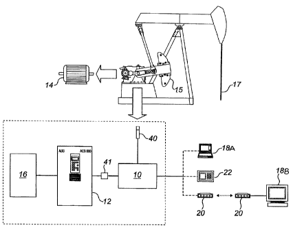
In one embodiment, the invention comprises an apparatus including a controller
(10) and
a variable speed drive (12), as illustrated in Figure 3. In use, the crank
speed specified by a crank
speed profile is applied to a variable speed motor (14) by the controller
having a servo motion
controller. The motor (14) rotates the crank arm (15) which results in
reciprocation of the rod
(17). The controller may be implemented in a general purpose computer
programmed with
appropriate software, firmware, a microcontroller, a microprocessor or a
plurality of
microprocessors, a digital signal processor or other hardware or combination
of hardware and
software known to those skilled in the art. The controller will physically
control the speed of the
motor through the variable speed drive (12). Suitable variable speed drives
may be AC or DC and
are well known in the art. In one embodiment, the drive may be a commercially
available variable
frequency AC drive such as an ABE ACS-601 (ABE Industry Oy, Helsinki, Finland)
or Allen-
Bradley 1336 Impact drive (Rockwell Automation) Milwaukee, Wis., USA).
Preferred variable
frequency drives allow for accurate control of motor speed and/or torque with
or without speed
feedback. If present, speed feedback may be provided by a pulse encoder on the
motor shaft or by
other well-known means. If the motor is a diesel engine, the controller (10))
may operate to open
or close a throttle (not shown) to achieve speed control.
A dynamic brake (16) is provided to control an overrunning load during the
portion of the
cycle where the rod string is falling or being decelerated. Dynamic brakes are
well-known in the
art of variable speed control systems. In some circumstances, the weight of
the rod string is
greater than the resistance provided by the viscosity of the fluid in the
oilwell and the friction
5of15
CA 02414646 2007-05-16
inherent in the pumping unit. Therefore, during the downstroke, the pumping
unit creates energy
which is imparted to the variable frequency drive through the electric motor.
In one embodiment, the
dynamic brake comprises a bank of resistor elements as is well-known in the
art. Line braking or
regenerative drive options may also be implemented.
In one embodiment, the controller (10) is a microprocessor and a user
interface (18A) is
provided by a separate general purpose personal computer (PC) such as a laptop
computer which is
operatively connected to the controller by suitable digital input/output. In
this embodiment, the PC
includes a memory which contains the mathematical model of the pumping unit
and which includes
software which allows a user to input a either a crank speed profile or a rod
speed profile. If the user
speed profile defines the crank speed profile, that is used directly to
control the crank speed by the
controller. If, however, the user speed profile defines a rod speed profile,
that must be converted to a
crank speed profile using the mathematical pumping unit model, which is then
used to control the
crank speed by the controller.
In another embodiment, the user interface (18A) is remotely located and
communicates with
the controller (10) by standard network communication protocols such as TCP/IP
or Ethernet
protocols. As shown in Figure 3, a remote workstation (18B) may communicate
with the controller
via telephone, RF, or satellite modems (20) associated with the workstation
(18B) and the controller
(10). A local display (22) for viewing user defined speed profiles and
charting results may be
provided where the user interface (1 8A) is provided remotely.
Figure 4 shows a schematic representation of one embodiment of the system of
the present
invention. The controller (10) is implemented separately from the user
interface (1 8A) as is shown in
Figure 3. However, in an alternative embodiment, the controller and user
interface may also be
implemented in a single box such as a general purpose computer. In a preferred
embodiment, the
user interface is implemented in software running on a general purpose
computer while the controller
is separately implemented in firmware.
The user interface (18A) includes a memory (22) where the mathematical model
of the pumpjack
geometry may be stored. Preferably, the user interface may also include a
software
6
CA 02414646 2006-09-28
module which allows selection of a known math model from a predefined pumpjack
geometry or
the creation and storage of a new math model. As seen in Figure 5, the math
model may be
selected from dropdown menus (30) corresponding to specific models from
selected
manufacturers. Alternatively, a new math model may be entered or created by
entering the
relevant values of the pumpjack geometry which may then be stored in the
memory and accessed
by other modules of the user interface.
The user interface may also include a module which pennits the rapid and
convenient
inputting of a user-defined rod speed profile (RSP) or a crank speed profile
(CSP). A user-defined
RSP may consist of a plurality of user-defined values such as initial, maximum
and terminal
upstroke speed and initial, maximum and terminal downstroke speed. The rate of
acceleration
may also be specified by the user or the user may accept a default value. In
one embodiment, one
or more profile types may be preconfigured, stored in memory and offered as
menu choices. In
one embodiment, two types of profiles are linear RSP's and linear CSP's. As
will be appreciated
by those skilled in the art, a linear or constant RSP may only be the result
of a curved CSP. On
the other hand, a linear CSP will result in a curved RSP.
Figure 6 depicts a screen shot of a software window used to define a linear
RSP. The
profile type is chosen from a dropdown menu (32) at the top right side of the
window. As may be
seen the rod speed in this example is limited to maximum value during both the
upstroke and
downstroke and the rate of acceleration or deceleration is relatively linear.
As will be apparent to
one skilled in the art, such an RSP will require the CSP to include a period
of gradual speed
decrease and increase, corresponding to the linear maximum rod speed. In this
example, the
acceleration rate is specified and the upstroke start and end speeds are the
same as are the
downstroke start and end speeds. The software will then convert the RSP to a
CSP and specify a
number of profile steps. Each profile step represents a speed change at a
specified crank position
as well as a crank acceleration value. As shown in Figure 6, a linear RSP may
be converted to a
CSP having 23 profile steps. In this example, the rod motion parameters are
used to determine the
CSP. However, in alternative embodiments, a user may enter a data table of RSP
steps each
consisting of a rod position and a desired rod speed at that position.
7of15
CA 02414646 2006-09-28
Figure 7 depicts a screen shot of a software window used to define a linear
CSP. The
profile type (Crank Speed--Dual) is chosen from the profile type dropdown menu
(32). This type
of CSP may be defined by a user by specifying the desired speed at
predetermined points in the
cycle. A CSP comprises a series of individual steps where each step consists
of the crank position
where the desired speed starts, the desired speed and the rate of
acceleration. A CSP in the form
of a data table having four steps (34) is shown in Figure 7. The CSP may also
be represented
graphically as may also be seen in Figure 7. The data table (34) and graphical
representation may
be generated by entering values into the data table or by specifying motion
parameters such as
maximum rotational speed during certain phases within a cycle.
Once a desired CSP or RSP has been defined by the user, the software may
provide a
simulation function to view the resulting CSP or RSP. Figure 8 depicts a
screen shot of a software
window showing the results of a linear RSP (the RSP shown in Figure 6)
simulation. In this case,
the RSP has been defined and the user can view graphically and in tabular
form, the resulting
simulated CSP.
In one embodiment, motor torque or loading on the sucker rod may be monitored
using
appropriate sensors. It is typically desirable to limit torque or rod loading
to certain maximum
values to prevent overloading the rod. A proportional integral derivative
(PID) control with a
scaling algorithm may be provided to adjust the speed control to stay within
certain parameters. If
measured torque exceeds a set maximum value, the scaling algorithm may be
invoked to scale
down the speed profile.
In a preferred embodiment, the variable frequency drive produces an actual
speed
reference, either from monitoring the voltage and current waveforms from the
motor or by some
other means. The speed reference is used to estimate the crank position at any
time during a
cycle. In one embodiment, the means for estimating crank position includes a
device for
producing an analog speed reference and a device for converting the speed
reference to square
wave pulse train having a frequency proportional to the speed. The speed, as
represented by the
square wave, may then be integrated to obtain a position of the crank by
counting the edges of the
8of15
CA 02414646 2006-09-28
square wave as would be done with input from a pulse encoder. In another
embodiment, the crank
position and speed may be directly measured using a pulse encoder.
Because the crank position is estimated during a cycle or there may be bolt
slippage or
other errors of a mechanical or electrical nature, it is desirable to provide
error correction means.
In one embodiment, error correction is provided by resetting the estimated
position with actual
position once every cycle. This may be accomplished by providing a proximity
switch or sensor
(40) affixed to a position on the pumping unit where it may sense the passing
of the crank arm
and produce an output signal upon the passing of the crank arm. The proximity
switch signal may
then be used to reset the estimated crank arm position derived from speed/time
calculations
performed by the controller, at the beginning of each cycle or once per cycle
at a specified point
during the cycle.
In a preferred embodiment, the actual speed reference may be used to produce
real time
speed profiles which may be charted and graphically displayed or recorded.
Particularly useful
may be a real time comparison of the menial speed profile with the user
defined speed profile.
This charting function may be part of the PC based software in the user
interface and may also
receive and chart such other data or variables such as motor current or
torque. Motor torque may
be reported by a torque sensor (41).
In one embodiment, an encoder may be provided to provide an actual crank arm
position
signal, in which case a proximity switch or other means of error correction
may not be necessary,
but may still be desirable to correct for mechanical errors such as belt
slippage.
An embodiment of the invention in its method form will now be described in
reference to
Figures 9 and 10.
Figure 9 is a flowchart presenting the steps involved in creating a series of
program steps
representing a CSP or a RSP. The first step is to either enter a CSP or a RSP
either by entering a
data table, program steps or a template of motion parameters (100). If a RSP
is entered, it is
necessary to convert the RSP values to a CSP (110), which is comprised of a
series of crank
speed settings in certain crank positions. The CSP table is then converted
(120) to a series of
9of15
CA 02414646 2007-08-08
program steps which may be downloaded (130) to the controller which is
operatively connected
to the variable frequency drive.
Figure 10 demonstrates the operation of the controller. The proximity switch
provides a
start of cycle signal (200) whereupon the variable frequency drive (VFD) ramps
up the crank
speed to the desired start speed (210), at the set rate of acceleration. The
position of the crank is
then estimated using an actual speed reference as described above and the next
program step
(220) is invoked at the appropriate position. At that position, the VFD speed
setpoint is either
increased or decreased at the desired acceleration and ibis process is
continued for all program
steps during the cycle. The proximity switch signals the end of a cycle which
is obviously
coincidental with the start of the next cycle. At this time, if PID scaling is
enabled and an
overtorque or rod overload condition was detected during the cycle, the speed
setpoints may be
scaled back and a new scaled speed profile created for the next cycle. The
scaling algorithm may
be designed so as to reduce all speed setpoints by a predetermined figure on
each cycle until the
torque is reduced to an acceptable level, as reported by the torque sensor
(41). Alternatively, the
scaling algorithm may be designed to sense the amount by which the torque
value has been
exceeded and reduce the speed setpoints by a percentage which aims to reduce
torque to an
acceptable level in one step. In one alternative embodiment, the scaling
algorithms may be
designed to scale back only a portion of the cycle, such as the upstroke
portion only.
As will be apparent to those skilled in the art, various modifications,
adaptations and
variations of the foregoing specific disclosure can be made without departing
from the scope of
the invention claimed herein. The various features and elements of the
described invention may
be combined in a manner different from the combinations described or claimed
herein, without
departing from the scope of the invention.
-10-