Note: Descriptions are shown in the official language in which they were submitted.
CA 02415164 2003-O1-07
DESCRIPTION
BLOOD PROCESSING FILTER
TECHNICAL FIELD
The present invention relates to a blood processing
filter for removing undesirable components such as aggregates
and leukocytes from the blood. The present invention
particularly relates to a precise and disposable blood
processing filter to be used for removing micro aggregates and
leukocytes, that cause side effects, from whole blood
preparations, erythrocyte preparations, thrombocyte
preparations, blood plasma preparations and the like for use
in blood transfusion. Especially, the blood processing filter
of the present invention is most suitable for being centrifuged
together with blood bags and the like in the centrifugation
operation carried out with an objective of separating blood
components.
BACKGROUND ART
The whole blood collected from a donor is used for
transfusion, as is, only in rare cases, but is commonly
separated into components, such as a erythrocyte preparation,
thrombocyte preparation,blood plasma preparation,and thelike.
Each component is then stored and is used for transfusion
thereafter. Since micro aggregates and leukocytes contained
in these blood preparations cause various side effects after
transfusion, there have been increasing occasions when these
1
CA 02415164 2003-O1-07
undesirable components are removed before blood transfusion.
The need of removing the leukocytes has been widely recognized
in recent years, and some European countries legislate the blood
preparations to use for transfusion after applying an treatment
for removing leukocytes . The most common method for removing
the leukocytes from the blood preparation is by processing the
blood preparation using a leukocyte removing filter.
Conventionally, blood preparation has been processed using the
leukocyte removing filter in many cases at the bedside when
blood transfusion is performed, it is now common to process the
blood before storage at the blood center for assuring quality
control of the blood preparations after removing the leukocytes,
and for improving efficiency of the leukocyte removing
treatment. A blood collection-separation set, typically
composed of two to four flexible bags, tubes connecting these
bags, an anticoagulant, an erythrocyte preservation solution,
a blood collecting needle, and the like, has been used for
collecting blood from a donor, separating the blood into several
blood components, and storing the blood components. A system
in which the leukocyte removing filter is
integrated/incorporated into the blood collection-separation
set has been widely used as a system that can be favorably used
for removing of the leukocytes before storage. Such a system
is called a "closed system" or an integrated system" and the
like. Such a system is disclosed, for example, in Japanese
Patent Application Zaid-open Publication No. O1-320064 and WO
92/20428.
2
CA 02415164 2003-O1-07
Conventionally, a filter made from non-woven fabric or
porous filter elements packed in a hard container such as
polycarbonate has been widely used as a leukocyte removing
filter. However, it has been difficult to use a vapor
sterilization method, that is widely used for sterilization of
blood collection-separation sets, since the container does not
have gas permeability.
In a closed system, leukocytes are first removed from
the whole blood preparation after collecting the blood. Then,
IO after the leukocyte removing filter is separated, the
leukocyte-free blood is centrifuged for separation into various
components. Then, after the leukocyte removing filter is
separated, the leukocyte-free blood is centrifuged for
separation into various components. In another type of closed
system, the whole blood is first centrifuged to be divided into
various components, and then the leukocytes are removed. In
the latter system, the leukocyte removing filter is also
centrifuged together with the blood collection-separation set.
In this instance, a hard container may damage bags and tubes,
or the container itself may not withstand the stress and may
collapse during centrifugation.
To solve this problem, flexible leukocyte removing
filters, in which the container is made of the same or a similar
material having superior flexibility and high vapor
permeability as used for the bags of the blood
collection-separation set, have been developed (EP 0526678 and
Japanese Patent Application Laid-open Publication No.
3
CA 02415164 2003-O1-07
11-216179).
However, these leukocyte removing filters have a problem
of a complicated manufacturing process, since a sheet of
flexible frame must be welded to a housing material after
welding the filter element to the flexible frame. It has also
been a problem that a large portion of the starting material
is wasted since an effective filtration part is produced by
punching the sheet inside the frame.
Flexible leukocyte removing filters not using a sheet
of the frame are disclosed in Japanese Patent Application
Laid-open Publication No. 07-267871 and WO 95/17236. These
filters have some risk, however, because the outermost
circumference periphery of the filter element are welded and
the welded part has become a plate of hard plastic. Similar
to conventional filters made of a hard plastic container, the
hard plastic may damage bags and tubes . In addition, the welded
part has a risk of being broken due to stress during
centrifugation.
In particular, the former filter having the outermost
peripheries of the filter element welded with the container
material cannot avoid the risk of exposing the medical workers
to the danger of infection or cannot prevent blood preparations
from being contaminated with miscellaneous bacteria, when
leaking resulting from breakage of the welded parts due to
operational mistakes, rough handling, stress of centrifugal
operation, or the like during filtration. On the other hand,
the latter leukocyte removing filter, which also has the
4
CA 02415164 2003-O1-07
outermost peripheries of the filter element welded with the
container material, is designed to reduce the risk of leaking
by covering the peripheries of the filter element with the
container material. However, the filter has a structure
precluding detection of potential cracks which allow blood to
pass through in the welded parts of the filter element. For
this reason; even if no leakage to outside takes place, blood
may bypass the proper route of the filter element and pass
through short passages such as cracks and inappropriately
welded parts, resulting in a risk of decreasing the leukocyte
removing function. This type of filter cannot thus detect such
a risk.
DISCLOSURE OF THE INVENTION
A first object of the present invention is to provide
a blood processing filter that makes it possible to manufacture
a flexible blood processing filter without using a sheet-like
flexible frame and thus without a. complicated manufacturing
process or increase of loss of the starting materials . A second
obj ect of the present invention is to provide a blood processing
filter that can protect the medical workers from the risks of
exposure to infections or prevent contamination of the blood
preparations with bacteria, even when the seal portions between
the filter element and the container are broken to cause leakage
by operational mistakes or rough handling during filtration,
and by stress during centrifugation . An another obj ect of the
present invention is to provide a blood processing filter having
5
CA 02415164 2003-O1-07
a construction which, in the case where the blood by-passes
through cracks or insufficiently welded portions without
passing through the filter element as a proper passage for the
blood, resulting in decreasing the leukocyte removing function
of the filter element, can detect such risks by inspection
during the manufacturing process of the filter.
As a result of extensive studies to achieve the above
objects, the inventors of the present invention have found that
the above obj ects can be surprisingly achieved at the same time
by integrating the flexible container with the filter element
in a first seal zone, forming a second seal zone integrated the
inlet port side flexible container with the-outlet port side
flexible container outside the first seal zone, and providing
an unsealed zone between them.
As a result of a further study with an objective of
obtaining a blood processing filter with welded parts not easily
broken, the inventors have found that all of the above obj ects
can be achieved by integrating the flexible container with the
filter element in the first seal zone, forming the second seal
zone to integrate the flexible container outside the first seal
zone , and providing an unsealed zone between them, and further
providing a peripheral end of the filter element with a width
of 2-25 mm over the entire circumference of the unsealed zone.
These findings have led to the completion of the present
invention.
Specifically, the present invention provides a blood
processing filter comprising a flexible container having an
6
CA 02415164 2003-O1-07
inlet port and an outlet port for the blood and a filter element
for removing undesirable components from blood, the filter
element partitioning the inlet port from the outlet port for
the blood, comprising: a first seal zone formed by integrating
the entire circumference in the vicinity of the periphery of
the filter element with the flexible container; a second seal
zone formed by integrating the inlet port side flexible
container with the outlet port side flexible container over the
entire outer circumference of the first seal zone; and an
unsealed zone with a width of 1-30 mm between the first seal
zone and the second seal zone.
In another aspect, the present invention provides a blood
processing filter comprising a flexible container having an
inlet port and an outlet port for the blood, and a filter element
for removing undesirable components .from the blood, wherein the
inlet port and outlet port for the blood are partitioned by the
filter element, comprising: a first seal zone formed by
integrating the entire circumference in the vicinity of the
peripheral end of the filter element with the flexible
container; a second seal zone formed by integrating the inlet
port side flexible container with the outlet port side flexible
container over the entire outer circumference of the first seal
zone; an unsealed zone provided between the first seal zone and
the second seal zone; and a peripheral end of the filter element
with a_width of 2-25 mm over the entire circumference of the
filter element within the unsealed zone.
The peripheral end of the filter element existing within
7
CA 02415164 2003-O1-07
the unsealed zone is hereinafter referred to as "protruding
filter material" from time to time.
BRIEF DESCRIPTION OF THE DRAWINGS
Figure 1 is a schematic sectional view of one embodiment
of the blood processing filter of the present invention.
Figure 2 shows one embodiment of the process for
manufacturing the blood processing filter of the present
invention.
Figure 3 shows another embodiment of the process for
manufacturing the blood processing filter of the present
invention.
BEST MODE FOR CARRYING OUT THE INVENTION
The present invention will be described in more detail
below.
The overall shape of the blood processing filter of the
present invention may be rectangular, lozenge-shaped,
disk-like, oval, or the like. A rectangular or lozenge-shaped
filter is preferable for decreasing loss of materials when
manufacturing the filters. In the present invention, a square
is classed as a rectangle.
The flexible container used in the present invention is
preferably formed from a flexible sheet-like or a cylindrically
formed object of a synthetic resin, preferably a thermoplastic
resin. The flexible container may be formed by injection
molding or the like as an integrally molded body with an inlet
8
CA 02415164 2003-O1-07
port and outlet port for the blood. Alternatively, holes or
slits may be formed on a sheet or cylinder of film manufactured
by extrusion molding, to which an separately molded parts for
inlet port and outlet port are liquid-tightly and
communicatingly connected by a known method, such as a method
of using an adhesive, heat sealing, high frequency welding, or
the like. The latter method is more preferable because the
container is deformed only with difficulty duririg vapor
sterilization. The material of the inlet and outlet parts may
be the same as or different from the material of the molded film.
Although the material is not particularly restricted so far as
the inlet port and outlet port are capable of being j oined to
the molded film with no gaps and of being liquid-tight, in
addition to causing no trouble in handling, the materials
preferably have similar thermal and electrical properties.to
the molded film, because heat sealing and high frequency.molding
methods are advantageously used for mass production. Suitable
j oining is possible by the high frequency welding method when
materials having a relatively high dielectric constant such as
soft vinyl chloride are welded to one another, while the
material having a relatively low dielectric constant and a low
melting point such as polyolefin can be favorably joined by heat
sealing.
The material for the flexible container preferably has
thermal and electrical properties similar to the material for
the filter element . As examples of such a suitable material ,
thermoplastic elastomers such as soft polyvinyl chloride,
9
CA 02415164 2003-O1-07
polyurethane, an ethylene-vinyl acetate copolymer, polyolefin
such as polyethylene and polypropylene, hydrogenated
styrene-butadiene-styrene copolymer,
styrene-isoprene-styrene copolymer or the hydrogenated
product thereof, and mixtures of the thermoplastic elastomer
and a softening agent such as polyolefin and ethylene-ethyl
acrylate, and the like can be given. Of these, preferable
materials are thermoplastic elastomers such as soft polyvinyl
chloride, polyurethane, ethylene-vinyl acetate copolymer;
polyolefin, and mixtures containing these thermoplastic
elastomers as a major component, with particularly preferable
materials being soft polyvinyl chloride and polyolefin.
While any material is suitable for the sheet of the filter
element in the present invention so far as it can remove
undesirable componentsfrom the blood, the materials preferably
include such a filter element that is able to remove leukocytes.
More preferably, the filter element of the present invention
includes the first filter element for removing aggregates from
the blood at the inlet side, the second filter element for
removing the leukocytes', and the third filter element arranged
for preventing adhesion of the element for removing the
leukocytes to the outlet port side container.
Filter media known in the art such as a fibrous and porous
medium such as a non-woven fabric and a porous medium having
continuous pores of a three-dimensional network may be used as.
the filter element in the present invention. The materials for
such fiber media include polypropylene, polyethylene,
CA 02415164 2003-O1-07
styrene-isobutylene-styrene copolymer, polyurethane,
polyester, and the like.
A combination of filter elements having different fiber
diameters and pore sizes is usually used. In the case of the
filter element comprising the first to third filter elements,
a filter material having a fiber diameter of several to several
tens of microns is arranged as the first filter element for
removing aggregates, a filter material having a fiber diameter.
of 0.3-3.0 Eun is then arranged as the second filter element for
removing leukocytes, and a filter material having a fiber
diameter of several to several tens of microns is laminated as
the third filter element between the second filter element and
the outlet port side container for preventing the outlet side
container from adhering to the second filter element.
Each of the first, second, and third filter elements may
be formed from two or more different filter elements . In this
instance, these filter elements are preferably arranged so that
the fiber diameter increases stepwise or continuously from the
portion of the second filter element having the smallest fiber
diameter toward the inlet and the outlet.
In the same manner, when porous materials having a
three-dimensional network of continuous fine pores are used,
the filter elements are preferably arranged so that the pore
size increases stepwise or continuously from the portion of the
second filter element with the smallest pore size toward the
inlet and the outlet.
A method such as internal welding by high frequency
11
CA 02415164 2003-O1-07
welding or by supersonic wave welding, external welding by heat
sealing, adhesion using a potting agent, or the like can be used
for forming the first seal zone, specifically, for joining the
flexible container with the vicinity of the periphery of the
filter element. The high frequency welding method is
preferably used when both the flexible container and the filter
element are made from materials with a comparatively high
dielectric constant, and heat sealing is preferably used when
either material has a low dielectric constant or both materials
have a low melting point.
The first seal zone may be formed either by a two-step
welding method by which, after the vicinity of the periphery
of the filter element is once welded, the welded portion is
further welded to the flexible container, or by a one step
welding method by which the filter element and the flexible
container are simultaneously welded. The one step welding
method is more preferable for simplifying the manufacturing
process.
Although the first seal zone is not necessarily formed
by j oining the entire filter element to the flexible container,
at least the filter element for removing the leukocytes must
be welded to the flexible container, when the filter element
includes the filter element for removing the leukocytes in
addition to a laminatedlayer having different functions. This
is because if the filter element for removing the leukocytes
is not integrated with the flexible container, the leukocyte
removing function deteriorates due to bypassing.
12
CA 02415164 2003-O1-07
Although the width of the first seal zone is not
particularly restricted, it is preferably within a range of 1-7
mm, more preferably 2-5 mm, in view of reliability of the seal
and easy handling of the filter. If less than 1 mm, the joined
part becomes like a line, which has a risk of failing to exhibit
sufficient sealing performance when subjected to high-pressure
vapor sterilization or roughly handled. If the width is larger
than 7 mm, the characteristics as the flexible container are
partly lost because the width of the seal zone portion that tends
to be hardened by high frequency welding, heat sealing, or
impregnation of the potting agent becomes too large. This
unfavorably causes the filter element to become fragile against
bending stress or deformation occurring during centrifugation,
precluding the protruding filter material from sufficiently
exhibiting its protective effect.
The first seal zone may be formed either in the outermost
periphery of the filter element or in a portion slightly inside
the outermost periphery. The latter case is more preferable,
particularly when the first seal zone is formed by high
frequency welding or by heat sealing. Specifically, it is
desirable to ensure superior process stability that the first
seal zone is formed in an inner position than a point of 2-25
mm inside from the peripheral end of the filter element so that
about a several mm margin may be left unsealed outside the first
seal zone.
The unsealed filter element formed within the unsealed
zone must be present over the entire circumference with a width
13
CA 02415164 2003-O1-07
of 2-25 mm. When the blood processing filter is centrifuged
together with the blood collection-separation set, the
protruding filter material functions as a cushion, protecting
the blood bags and circuits of the blood collection-separation
set from being harmed and, at the same time, ' reducing the risk
of the blood processing filter being damaged by the centrifuge
operation.
One typical example of the damage to the blood processing
filter due to centrifuge operation will be described. There
are various types of centrifuge cups and the manner of arranging
the blood collection-separation set and the blood processing
filter in a centrifuge cup varies according to the type of the
centrifuge cup. Here, the operation of a one-litter
cylindrical centrifuge cup typically used in the United States
will be discussed.
A blood bag made of soft polyvinyl chloride containing
570 ml of a whole blood preparation treated for anti-aggregation,
a blood processing filter, a bag made of soft polyvinyl chloride
containing about 100 ml of an erythrocyte preservation solution,
an empty bag for transferring thrombocyte-rich plasma after
centrifugation, and an empty bag to store the blood after
processing with the blood processing filter are arranged in this
centrifuge cup in the order to be centrifuged Tubes made of soft
polyvinyl chloride to connect the bags to the filter are
appropriately arranged between the bags and the filter. Each
bag and the filter are pushed to the bottom of the centrifuge
cup by centrifugal force. The bag containing the whole blood
14
CA 02415164 2003-O1-07
preparation and the bag containing the erythrocyte preservation
solution are deformed to inflate. As a result, the flexible
blood processing filter placed between the two blood bags may
be crushed by the blood bags or may be deformed into a
configuration conforming to the inflated blood bags. As a
result, the sealed portion of the filter element and flexible
container denatured into hard plastic due to welding and the
like is bent, resulting in formation of cracks and peeling and
giving rise to leakage. If the sealed portion is pushed to the
bottom of the centrifuge cup, the sealed portion may crack due
to the stress and cause leakage. If a member similar to the
protruding filter material of the present invention is provided,
the member acts as a cushion against the stress created by the
deformation or pushing to the bottom. The distortion generated
in the sealed portion of the filter element and the flexible
container is reduced, thereby protecting the sealed portion.
As a result, the risk of damage is remarkably decreased. At
the same time, the protruding filter material prevents the
adjacent blood bags and tubes in the centrifuge cup from
directly contacting the sealed portion of hardened plastic,
thereby protecting the blood bags and tubes from being damaged.
If the width of the protruding filter material is less
than 2 mm, a sufficient effect may not be obtained. On the other
hand, the width more than 25 mm lacks practical advantage,
although the function and effect will not be affected. When
applied to the above-described typical centrifuge cup, the
width of the protruding filter material not contributing to the
CA 02415164 2003-O1-07
filtration occupies about two-thirds of the whole width of the
filter. Although a width of 2 mm or more is sufficient for the
protruding filter material, 3 mm or more is preferable in view
of mass production and ease of handling, with 4 mm or more being
more preferable, and 5 mm or more being most preferable.
Although a width of 25 mm or less is practicable for the
protruding filter material, 20 mm or less is preferable in view
of the duration of leak inspection, with 15 mm or less being
more preferable, and 10 mm or less being most preferable.
It is desirable that the width of the protruding filter
material be uniform, with the difference between the largest
width and the smallest width being 3 mm or less, more preferably
2 mm or less, and still more preferably 1 mm or less. A large
difference between the largest width and the smallest width may
result in a risk of concentrating the stress on the smallest
width portion during centrifugal operation. Therefore, too
large a width difference is undesirable.
The protruding filter material may be formed from all
components forming the filter element in the effective
filtration area or may be formed from a part of such components .
The components maybe appropriately selected to the extent that
the desired cushion effect can be obtained. However, using all
components forming the filter element in the effective
filtration area is more preferable in view of simplicity of the
manufacturing process.
It is necessary that the second seal zone be formed over
the entire circumference at the outside of the first seal zone,
16
CA 02415164 2003-O1-07
and the inlet port side flexible container be integrated with
the outlet port side flexible container. Due to this
configuration the filter can avoid the risk of exposing the
medical workers to the danger of infection or prevent the blood
preparations from being contaminated with miscellaneous
bacteria, even if leakage is brought by breakage of the first
seal zone during the filtering operation due to operational
mistakes or rough handling, stress of centrifugal operation,
or the like.
The second seal zone can be formed by joining a flexible
container with another flexible container. Although known
methods such as internal welding by high frequency welding and
supersonic wave welding, external welding by heat sealing, and
adhesion using a solvent can be applied, high frequency welding
is preferably used when the flexible container is made of a
material with a comparatively high dielectric constant, and
heat sealing is preferably used when the material has a low
dielectric constant and a low melting point.
The width of the second seal zone is preferably 1-10 mm,
and more preferably 2-5 mm. If less than 1 mm, satisfactorily
sealing performance may not be relied upon. A width not
exceeding 10 mm is desirable because an unnecessarily wide weld
increases loss of raw materials.
The flexible container of the present invention may be
formed from either a sheet of film or a cylindrical film. When
the blood processing filter is formed from a sheet of .film, the
filter element may be inserted between two sheets of film or
17
CA 02415164 2003-O1-07
within a sheet of folded film. When the first seal zone is
formed by inserting the filter element within a sheet of folded
film, the second obj ect of the present invention can be achieved
by sealing only the open three sides without forming a second
seal zone over the entire circumference. This feature is also
within the scope of the present invention. When the first seal
zone is formed by placing the first filter element inside a
cylindrical film, the second object of the present invention
can be achieved by sealing only the open two sides without
forming a second seal zone over the entire circumference. This
feature is also within the scope of the present invention.
It is essential that an unsealed zone, surrounded by the
flexible container, the first seal zone, and the second seal
zone, be formed between the first seal zone and the second seal
zone . The width of the unsealed zone should be within a range
of 1-30 mm. When the width is less than 1 mm, the filter element
may be engaged with the area when the second seal zone is caused
to adhere. In addition, it is difficult to detect leakage in
the first seal zone as will be discussed hereinafter. A width
exceeding 30 mm, on the other hand, is not practical because
it takes a long time to detect leakage in the first seal zone.
Leakage in the first seal zone can be detected by a method
of inspection comprising, for example, closing the tube on the
outlet side of the blood processing filter with a clamp, feeding
air under a pressure of 0.02 MPa from the inlet side, and
maintaining this condition for a prescribed period of time, for
example, for 1 minute to 1 hour, according to the width of the
18
CA 02415164 2003-O1-07
unsealed zone. In this instance, if leakage occurs, the
clearance between the welded portions of the circumference (the
part indicated by h in the drawings) is inflated. Leakage can
be inspected by observing the inflation.
In the filter of the present invention, since a clearance
of 1-30 mm is provided between the first seal zone and the second
seal zone, the inner pressure of the filter decreases when
leakage occurs in the first seal zone. Consequently, the
leakage can be detected by measuring the pressure change, or
by visually observing the deformation of the unsealed zone due
to swelling resulting from the pressure of air coming into the
unsealed zone by leakage. Leakage can be easily detected in
this manner. The width of the unsealed zone is preferably 2
mm or more, and more preferably 4 mm or more, taking into account
the reliability and ease of leak inspection. From the viewpoint
of efficiency of leak inspection, the width of the unsealed zone
is preferably 20 mm or less, and more preferably 10 mm or less.
Leakage cannot be detected by this inspection method when
using the filter disclosed in WO 95/17236, in which the seal
24 zone at the edge of the filter element is covered by being welded
with the container material . In this type of filter, even when
leakage causing bypassing of the blood occurs in the seal zone
at the edge of the filter element, the inner pressure of the
filter does not change because the blood does not leak to the
outside of the filter.
In addition, when a non-woven fabric protrudes beyond
the unsealed zone, the width of the unsealed zone is preferably
19
CA 02415164 2003-O1-07
larger by 1 mm or more, preferably by 2 mm or more, than the
width of the protruding non-woven fabric. If less than 1 mm,
part of the protruding filter material is engaged with the
second seal zone, resulting in impaired appearance and
decreased reliability of the second seal zone. On the other
hand, the width of the non-seal zone need not be larger by more
than 10 mm than the width of the protruding filter material.
An unnecessarily wide area impairs ease of handling. A width
of the non-seal zone 2-5 mm larger than the protruding filter
material is more preferable, with a width 3-4 mm larger being
ideal. As described above, a cushion effect can be obtained
if the protruding filter material is arranged in the area.
An embodiment and a manufacturing process of the blood
processing filter of the present invention are shown in the
attached drawing, which should not be construed as limiting the
present invention.
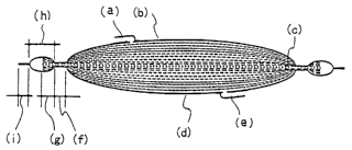
Figure 1 is a cross-sectional view of the blood processing
filter comprising an inlet port side flexible container made
of a resin sheet (b) equipped with a blood inlet port (a), an
outlet port side flexible container made of a resin sheet (d)
equipped with a blood outlet port (e) , and a filter element (c)
for removing undesirable components from blood, wherein the
blood inlet port (a) and outlet port (e) are separated by the
filter element (c) . The filter element (c) is inserted between
the inlet port side flexible container and outlet port side
flexible container and the vicinity of the periphery is
integrated with the flexible container over the entire
CA 02415164 2003-O1-07
circumference. A second seal zone (i), integrated by welding
the inlet port side flexible container and the outlet port side
flexible container, is formed outside the integrated first seal
zone (f). An unsealed zone (h) surrounded by the inlet port
side flexible container, the outlet port side flexible
container, the first seal zone (f), and the second seal zone
(i) is formed between the first seal zone (f) and the second
seal zone (i) . When the first seal zone (f) is formed slightly
inside the outermost.periphery of the filter element (c), a
non-sealed filter element (g) is provided protruding from the
first seal zone (f).
Figure 2 shows one embodiment of the process for
manufacturing the blood processing filter of the present
invention. A filter element (c) is inserted between two sheets
of film (j ) , (j ' ) , having either an inlet port (a) or an outlet
port, and a first seal zone (f) is formed by heat sealing. A
second seal zone (i) is further formed to provide an unsealed
zone (h) .
Figure' 3 shows another embodiment of the process for
manufacturing the blood processing filter of the present
invention, wherein the flexible container is formed from a
cylindrical film. A filter element (c) is inserted between a
cylindrical film (k) with an inlet (a) and an outlet being formed
therein, and a first seal zone (f) is formed by heat sealing.
A second seal zone (i) is further formed to provide an unsealed
zone (h) . In this case, the second seal zone (i) may be formed
only on the open end.
21
CA 02415164 2003-O1-07
EXAMPhES
The leukocyte removing filter of the present invention
will now be described in detail by way of examples, which should
not be construed as limiting the present invention. The
following leak inspection method was used in Examples and
Comparative Examples.
(Measuring method)
(1) Sterilization and centrifugation
An integral system consisting of a blood filter of the
present invention, a blood collecting bag A, a bag B for
transferring thrombocyte-rich plasma or blood plasma after
centrifugation, a bag C containing about 100 ml of erythrocyte
preservation solution, a bag D for receiving blood components
treated by the blood processing filter after centrifugation,
and tubes connecting these parts was prepared. A tube 1 for
collecting blood was connected to the upper part of the bag A.
Next, another tube 2, of which the one end was connected to the
upper part of the bag A, was branched via a Y-branched tube and
the other ends were connected with the bag B and bag C. A third
tube 3 extending from the top of the bag A to the bag D was
provided. The blood processing filter was joined at about
middle of the tube 3. After sterilizing the system with high
pressure vapor (at 121°C for 20 minutes) , the bag A was charged
with 570 ml of bovine whole blood containing CPD
(citrate-phosphate-dextrose) through the tube 1. The tube 1
was sealed by heat sealing at about 10 cm from the bag A and
22
CA 02415164 2003-O1-07
the other end was cut and separated. The system was placed in
a cylindrical centrifugal cup with an internal capacity of about
1 1 in the order of the bag A, blood processing filter, bag C,
bag D, and bag B. The tubes were appropriately inserted in the
void spaces of the bags or the blood processing filter. The
system was centrifuged using the following device and under the
following conditions.
Centrifuge device: CR7B3 (manufactured by Hitachi, Ltd.)
Radius of rotation: 0.261 m
Rotational speed: 4140 rpm
Centrifuge duration: 10 minutes
Dimension of cup: internal diameter 100 mm; height: 150 mm
(2) Leak inspection method of a blood processing filter with
only the first seal zone sealed
Tubes are connected to the blood inlet port and the blood
outlet port, respectively. The outlet port side tube is closed
with a clamp, and air is injected from the blood inlet port side
tube at a pressure of 0.02 MPa. The blood filter is kept under
the water surface for several minutes. Leakage is judged by
generation of air bubbles (hereinafter referred to as
~underwater leak inspection").
(3) Leak inspection method of a blood processing filter in which
the first and second seal zones are sealed
Tubes are connected to the blood inlet port side and the
blood outlet port side, respectively. The outlet side tube is
closed with clamp, and air is inj ected from the blood inlet port
side tube at a pressure of 0.02 MPa. The blood filter was kept
23
CA 02415164 2003-O1-07
in air for a time. If leakage occurs, the unsealed zone (h)
surrounded by the first and second seal zones is inflated.
Leakage can be inspected by observing this part. The time when
the inflation of the unsealed zone was confirmed by visual
inspection was measured for leaking filters (hereinafter
referred to as "visual inspection").
Example 1
Flexible polyvinyl chloride resin sheets (b, d), which
were cut to a size 20 mm larger than the size of the blood filter
and in which holes were made at the portions corresponding to
the blood inlet port and outlet port, and a blood inlet port
(a) and a blood outlet port (e) , formed from a polyvinyl chloride
resin by injection molding, were bonded by high frequency
welding, to produce an inlet port side flexible container (b)
provided with the blood inlet port (a) and an outlet port side
flexible container (d) provided with the blood outlet port (e) .
The polyester non-woven fabric described below was
laminated for use as the filter element (c). Four sheets of
non-woven fabric (non-woven fabric 1) with a mean fiber diameter
of l2-15 Nm and nicking (Metsuke) of 29-31 g/m2 were laminated
for use as the first filter element. Total of 27 sheets of the
non-woven fabric consisting of one sheet of non-woven fabric
(non-woven fabric 2) with a mean fiber diameter of 1.5-2.0 Elm
and nicking of 65-67 g/m2, 25 sheets of non-woven fabric
(non-woven fabric 3) with a mean fiber diameter of 1.2-1.4 Eun
and nicking of 39-41 g/m2, and one sheet of the non-woven fabric
2 were laminated in that order for use as the second filter
24
CA 02415164 2003-O1-07
element. Four sheets of the non-woven fabric (non-woven fabric
1) were laminated for use as the third filter element. The first,
second, and third filter elements were laminated in that order.
The laminated body comprising a total of 35 sheets of the
non-woven fabric as prepared above was cut into a size of 85
mm x 68 mm (rectangle) for use as the filter element (c) . The
flexible containers (b, d) and the filter element (c) were
layered in the order of the inlet port side flexible container
(b) , filter element (c) , and outlet port side flexible container
(d) and welded by high frequency welding to form a filtering
section with the dimension of 75 mm x 58 mm and the first seal
zone with the width (f) of the first seal zone of 3 mm. The
width of the protruding filter element (g) was 2 mm. High
frequency welding was purposely applied under a non-optimal
condition for forming the first seal zone so that leakage would
be occurred with a certain probability. The resulting blood
filters in which only the first seal zone has been sealed were
inspected according to the underwater inspection method, and
the filters were classified into leaky filters and non-leaky
filters.
.The protruding filter element (g) is impregnated with
water and water drops adhere to the surfaces of the sheets to
serve as the unsealed zone (h) and the second seal zone (i) after
the underwater leak inspection. Therefore, these filters were
once dried, and the flexible containers (b, d) were welded with
the filters by high frequency welding so that the width of the
unsealed zone (h) was 6 mm and the width of the second seal zone
CA 02415164 2003-O1-07
(i) was 3 mm. The final shape as shown in Figure 1 was obtained
by cutting the outermost periphery. Ten of final shaped leaky
filters and ten of non-leaky filters were inspected by visual
inspection. The results are shown in Table 1.
Example 2
A filter was prepared in the same manner as in Example
1 except that the first seal zone was welded using a sheet with
a size of 82 mm x 65 mm prepared by cutting the filter element
(c) so that the protruding filter element (g} with a width of
0 . 5 mm was provided and, after the leak inspection of the first
seal zone, the flexible containers (b, d) were welded so that
the unsealed zone (h) with a width of 1 mm is provided. The
leak inspection was carried out according to the method
described above. The results are shown in Table 1.
Example 3
A filter was prepared in the same manner as in Example
1 except that the first seal zone was welded using a sheet with
a size of 83 mm x 66 mm prepared by cutting the filter element
(c) so that the protruding filter element (g) is provided with
a width of 1 mm and, after the leak inspection of the first seal
zone, the flexible containers (b, d) were welded so that the
unsealed zone (h) is provided with a width of 2 mm. The leak
inspection was carried out according to the method described
above. The results are shown in Table 1.
Example 4
A filter was prepared in the same manner as in Example
1 except that the flexible containers (b, d) were welded so that
26
CA 02415164 2003-O1-07
the unsealed zone (h) of the blood filter is provided with a
width of 4 mm. Leakage was inspected by the method described
above. The results are shown in Table 1.
Example 5
A filter was prepared in the same manner as in Example
1 except that the flexible containers (b, d) were welded so that
the unsealed zone (h) of the blood filter is provided with a
width of 10 mm. Leakage was inspected by the method described
above: The results are shown in Table 1:
Example 6
A filter was prepared in the same manner as in Example
1 except that the flexible containers (b, d) were welded so that
the unsealed zone (h) of the blood filter is provided with a
width of 20 mm. Leakage was inspected by the method described
above. The results are shown in Table 1.
Example 7
A filter was prepared in the same manner as in Example
1 except that the flexible containers (b, d) were welded so that
the sealed zone (h) of the blood filter is provided with a width
of 30 mm. Leakage was inspected by the method described above.
The results are shown in Table 1.
27
CA 02415164 2003-O1-07
TABLE 1
Example
1 2 3 4 5 6 7
Filter size (mm) length99 89 91 95 107 127 147
width 82 72 74 78 90 110 130
Size of filter elementLength85 82 83 85 85 85 85
outermost
circumference (mm) ~,"qd~68 65 66 68 68 68 68
Size of Blood filter length75 75 75 75 75 75 75
filtration
area (mm) width 58 58 58 58 58 58 58
Width of first seal 3 3 3 3 3 3 3
zone f (mm)
Width of protruding 2 0.5 1 2 2 2 2
seal zone g (mm)
Width of non-seal 6 1 2 4 10 20 30
zone h (mm)
Width of second seal 3 3 3 3 3 3 3
zone l (mm)
Leak inspection ratio
for fist seal zone 101101011010/1010/101011010/1010/10
leak product
Leak inspection ratio 0/10 0/10 0/10 0110 0/10 0/10 0/10
for fist seal zone
non-leak product
Leak inspection time
for fist seal zone 13 2 4 8 60 600 1800
leak product {sec)
Comparative Example 1
A filter, was prepared in the same manner:as in Example
1 except that the first seal zone was welded using a sheet with
a size of 81 mm x 64 mm prepared by cutting the filter element
(c) so that the protruding filter element (g) is provided with
a width of 0 mm and, after the leak inspection of the first seal
zone, the flexible containers (b, d) were welded so that the
unsealed zone (h) is provided with a width of 0 mm. It was
difficult for the first seal zone to be welded in a stable manner
by high frequency welding due to frequent sparks . In addition,
in some cases the end of the first seal zone invaded the second
28
CA 02415164 2003-O1-07
seal zone, making it impossible to weld the second seal zone.
The filters without these problems were selected for leak
inspection. However, the visual inspection could not judge
whether or not these filters were leaky or non-leaky. The
results of the visual inspection are shown in Table 2.
Comparative Example 2
A filter was prepared in the same manner as in Example
2 except that the flexible containers (b, d) were welded so that
the unsealed zone (h) of the blood filter is provided with a
IO width of 0.5 mm. In some cases, the protruding filter element
(g) invaded the second seal zone, making it impossible to weld
the second seal zone. The filters without these problems were
selected for leak inspection. However, it was difficult to
judge whether or not these filters were leaky or non-leaky by
visual inspection. The results of the visual inspection are
shown in Table 2.
Comparative Example 3
A filter was prepared in the same manner as in Comparative
Example 1 except that the flexible containers (b, d) were welded
so that the unsealed zone (h) of the blood filter is provided
with a width of 0. 5 mm. Stable welding was difficult as in the
case of Comparative Example 1, and it was difficult to judge
whether or not these filters were leaky or non-leaky by visual
inspection as in the case of Comparative Example 2 . The results
of the visual inspection are shown in Table 2.
Comparative Example 4
A filter was prepared in the same manner as in Example
29
CA 02415164 2003-O1-07
0 except that the first seal zone was welded using a sheet with
a size of 81. 6 mm x 64 . 6 mm prepared by cutting the filter element
(c) so that the protruding filter element (g) with a width of
0.3 mm was provided and, after the leak inspection of the first
seal zone, the flexible containers (b, d) were welded so that
the unsealed zone (h) with a width of 0.5 mm is provided. The
leak inspection was carried out according to the method
described above. The results are shown in Table 2.
Comparative Example 5
A filter was prepared in the same manner as in Example
1 except that the flexible containers (b, d) were welded so that
the unsealed zone (h) of the blood filter is provided with a
width of 35 mm. Leakage was inspected by the method described
above. The results are shown in Table 2.
30
CA 02415164 2003-O1-07
TABLE 2
Example
1 2 3 4 5
Filter size (mm) lengthg7 gg 8g 88 157
70 71 71 71 140
Size of filter elementlengthg1
outermost
82 81 81.6 85
circumference (mm)
width~ 65 64 64.6 68
Size of Blood filter length75 75 75 75
filtration
75
area (mm)
width58 58 58 58 58
Width of first seal 3 3 3 3 3
zone f (mm)
Width of protruding 0 0.5 0 0.3 2
seal zone g (mm)
Width of non-seal zone 0 0.5 0.5 0.5 35
h (mm)
Width of second seal 3 3 3 3 3
zone i (mm)
Leak inspection ratio
for fist seal zone
0/10 2110 5/10 3/10 10/10
leak product
Leak inspection ratio
for fist seal zone
0/10 0/10 0/10 0110 0/10
non-leak product
Leak inspection lime
for fist seal zone
_ 20 20 20 3600
leak product (sec)
The results of Tables 1 and 2 indicate that if the unsealed zone
has a width of 1-30 mm, superior results are obtained in both
the leakage ratio and the time required for inspection.
Example 8
The inlet port side flexible container (b) , outlet port
side flexible container (d), and the filter element (c) were
prepared in the same manner as in Example 1.
The flexible containers (b, d) and the filter element
(c) were layered as shown in Figure 1 and welded by high frequency
one step welding to form a filtering area with a dimension of
31
CA 02415164 2003-O1-07
75 x 58 mm and the first seal zone with a width (f) of 3 mm.
The width (g) of the protruding filter element was 2 mm, with
the difference between the maximum width and minimum width being
1 mm or less . Flexible containers (b, d) were prepared by high
frequency welding so that the unsealed zone is provided with
a width (h) of 5 mm and the second seal zone is provided with
a width (i) of 3 mm. The outermost periphery was cut to obtain
the final shape shown in Figure 1. The blood processing filters
were inspected by the method described above. The filters
exhibiting no leakage in the first seal zone were used for the
above-described sterilizationlcentrifuge operation. The
leakage was inspected according to the above-described method.
The results are shown in Table 3.
Example 9
A blood processing filter was prepared in the same manner
as in Example 8, except that a filter material cut to a size
of 87 x 70 mm was used to prepare a protruding filter element
with a width (g) of 3 mm, and the unsealed zone was provided
with a width of 6 mm. The difference between-the maximum width
and minimum width of the protruding filter element was l mm.
The filters were used for the above-described
sterilization/centrifuge operation. The leakage was
inspected according to the above-described method before and
after the sterilization/centrifuge operation. The results are
shown in Table 3.
Example 10
A blood processing filter was prepared in the same manner
32
CA 02415164 2003-O1-07
as in Example 8, except that a filter material cut to a size
of 89 x 72 mm was used to prepare a protruding filter element
with a width (g) of 4 mm, and the unsealed zone was provided
with a width of 7 mm. The difference between the maximum width
and minimum width of the protruding filter element was 1 mm.
The leakage was inspected according to the above-described
method before and after the sterilization/centrifuge operation.
The results are shown in Table 3.
Example 11
A blood processing filter was prepared in the same manner
as in Example 8, except that a filter material cut to a size
of 91 x 74 mm was used to prepare a protruding filter element
with a width (g) of 5 mm, and the unsealed zone was provided
with a width of 8 mm. The difference between the maximum width
and minimum width of the protruding filter element was 1 mm.
The leakage was inspected according to the above-described
method before and after the sterilization/centrifuge operation.
The results are shown in Table 3.
Example 12
A blood processing filter was prepared in the same manner
as in Example 8; except that a filter material cut to a size
of 97 x 80 mm was used to prepare a filtering area with a size
of 71 x 54 mm, a protruding filter element with a width (g) of
10 mm, and the unsealed zone was provided With a width of 13
mm. The difference between the maximum width and minimum width
of the protruding filter element was 1 mm. The leakage was
inspected according to the above-described method before and
33
CA 02415164 2003-O1-07
after the sterilization/centrifuge operation. The results are
shown in Table 3.
Example 13
A blood processing filter was prepared in the same manner
as in Example 8, except that a filter material cut to a size
of 87 x 80 mm was used to prepare a filtering area with a size
of 51 x 44 mm, a protruding filter element with a width (g) of
mm, and the unsealed zone was provided with a width of 18
mm. The difference between the maximum width and minimum width
10 of the protruding filter element was 1 mm. The leakage was
inspected according to the above-described method before and
after the sterilization/centrifuge operation. The results are
shown in Table 3.
Example 14
15 A blood processing filter was prepared in the same manner
as in Example 8, except that a filter material cut to a size
of 87 x 80 mm was used to.prepare a filtering area with a size
of 31 x 24 mm, a protruding filter element with a width (g) of
mm, and the unsealed zone was provided with a width of 28
20 mm. The difference between the maximum width and minimum width
of the protruding filter element was 1 mm. The leakage was
inspected according to the above-described method before and
after the sterilization/centrifuge operation. The results are
shown in Table 3.
25 Example 15
A blood processing filter was prepared in the same manner
as in Example 11, except that a filter material cut to a size
34
CA 02415164 2003-O1-07
of 93 x 76 mm to prepare a first seal zone with a width (f) of
4 mm was used. The difference between the maximum width and
minimum width of the protruding filter element was 1 mm. The
leakage was inspected according to the above-described method
before and after the sterilization/centrifuge operation. The
results are shown in Table 3.
Example 16
A blood processing filter was prepared in the same manner
as in Example 11, except that a filter material cut to a size
of 97 x 80 mm to prepare a first seal zone with a width (f) of
6 mm was used. The difference between the maximum width and
minimum width of the protruding filter element was 1 mm. The
leakage was inspected according to the above-described method
before and after the sterilization/centrifuge operation. The
results are shown in Table 3.
Example 17
A blood processing filter was prepared in the same manner
as in Example 8, except that a filter material cut to a size
of 83 x 66 mm was used to prepare a first seal zone with a width
(f) of 2 mm and a protruding filter element with a width (g)
of 2 mm. The difference between the maximum width and minimum
width of the protruding filter element was 1 mm. The leakage
was inspected according to the above-described method before
and after the sterilization/centrifuge operation. The results
are shown in Table 3.
Example 18
A blood processing filter was prepared in the same manner
CA 02415164 2003-O1-07
as in Example 17, except that a filter material cut to a size
of 93 x 76 mm was used to prepare a first seal zone with a width
(f) of 2 mm and a protruding filter element with a width (g)
of 7 mm, and the unsealed zone was provided with a width of 10
mm. The difference between the maximum width and minimum width
of the protruding filter element was 1 mm. The leakage was
inspected according to the above-described method before and
after the sterilization/centrifuge operation. The results are
shown in Table 3.
Example 19
A blood processing filter was prepared in the same manner
as in Example 8, except that a filter material cut to a size
of 97 x 80 mm was used to prepare a filtering area with a size
of 63 x 46 mm, a first seal zone with a width (f) of 7 mm, and
a protruding filter element with a width (g) of 10 mm, and the
unsealed zone was provided with a width of 13 mm. The difference
between the maximum width and minimum width of the protruding
filter element was 1 mm. The leakage was inspected according
to the above-described method before and after the
sterilization/centrifuge operation. The results are shown in
Table 3.
Example 20
A blood processing filter was prepared in the same manner
as in Example 19, except that a filter material cut to a size
of 87 x 80 mm was used to prepare a filtering area with a size
of 43 x 36 mm, a first seal zone with a width (f) of 7 mm, and
a protruding filter element with a width (g) of 15 mm, and the
36
CA 02415164 2003-O1-07
unsealed zone was provided with a width of 18 mm. The difference
between the maximum width and minimum width of the protruding
filter element was 1 mm. The leakage was inspected according
to the above-described method before and after the
sterilization/centrifuge operation. The results are shown in
Table 3.
Example 21
The filters were prepared in the same manner as in Example
11 and those having a difference between the maximum width and
minimum width of the protruding filter element of 2 mm were
subjected to the leak inspection according to the
above-described method before and after the
sterilization/centrifuge operation. The results are shown in
Table 3.
Example 22
The filters were prepared in the same manner as in Example
11 and those having a difference between the maximum width and
minimum width of the protruding filter element of 3 mm were
subjected to the leak inspection according to the
above-described method before and after the
sterilization/centrifuge operation. The results are shown in
Table 3.
37
CA 02415164 2003-O1-07
_ O O
N ~ OOOO ~ ~ LI)M ~ GO M M
_ O O_
N O ~ ~ ~ ~ ~ M InCO M N
O O
O O N 1~ O M ~D ~ tnCO M T
N O O a0 a0 ~ M T r-
~ 000CMD~ ~ ~ ~ M T O O
'" O O
O O_
Cp O f~ I~ 1t~~ ~ ~ M T O O
O O
~ ~ aM0~ ~ ~ N N tO M T ~ O
O_ O
~ a00~ ~ ~ tL)a0 M T O O
m
D.
x e~-~ CMD~ ~ ~ ~ ~ lI7GO M T 0 0
O O
~tO N h- O r- ~ ~"~tpo0 M T 0 0
r-O O CO CO M N N N p O
M ~ N f~-O r- ~ tn00 OT O
T O O op CO tn d' ~ T T M ~ O O
M
~ COOf~ I~ M Or~ M r. O OT
T O O M
00 a1 ~ ~ 1~ M tn00 M T
T O O
C~OCOD~ ~ I~ M ~ I~ M T 0 0
O O
oNDCO ~ ~ ~ M M CG M T
p 0
t~ O l!7to tt700 ~"~N tn M ~, O_ O_
O o~ a0 CD 1~ tp
O O
m L m ~ . L E G7
C ~ C ~ as ~ ~ _ U
a~ .3 a~ .3 C .3 ... E ~
a~ a~
_E m
O O E N ~ O 't7 O C
:~. ..- .C p ~ ~ O
O ~ C m C N ~ .~..'L f3
N ~ m
~ N ~ o ~ ~3 m w
E N ~ ~ tn
O O ~
O o O O ~
E ~ t L L a
7 N p_ ~_~_ ~ ~ N
m O _ ~X.'-.
L (O ~ ~ ~ ~ J J
U fn ~ ~ Q
(U
CA 02415164 2003-O1-07
Comparative Example 6
A blood processing filter was prepared in the same manner
as in Example 8, except that a filter material cut to a size
of 83 x 66 mm was used to prepare a protruding filter element
with a width (g) of 1 mm, and the unsealed zone was provided
with a width of 4 mm. The difference between the maximum width
and minimum width of the protruding filter element was 0.5 mm.
The leakage was inspected according to the above-described
method before and after the sterilization/centrifuge operation.
The results are shown in Table 4.
Comparative Example 7
A blood processing filter was prepared in the same manner
as in Example 8, except that a filter material cut to a size
of 87 x 80 mm was used to prepare a filtering area with a size
of 25 x 18 mm, a protruding filter element with a width (g) of
28 mm, and the unsealed zone was provided with a width of 31
mm. The difference between the maximum width and minimum width
of the protruding filter element was 1 mm. The leakage was
inspected according to the above-described method before and
after the sterilization/centrifuge operation. The results are
shown in Table 4.
39
CA 02415164 2003-O1-07
TABLE 4
Comparative
Example
6 7
Filter size (mm) length95 99
width78 92
Size of filter elementlength83 87
outermost
circumference (mm) width66 80
Size of Blood filter length75 25
filtration
area (mm) width58 18
Width of first seal 3 3
zone f (mm)
Width of protruding 1 28
seal zone g (mm)
Width of non-seal zone 4 31
h (mm)
Width of second seal 3 3
zone i (mm)
Maximum/minimum width
difference of 0.5 1
protruding filter element
(mm)
Leak ratio before sterization 0110 0/10
Leak ratio after sterization 4/10 0110
The results of Tables 3 and 4 indicate that if the
protruding filter element is provided with a width of 2-25 mm
and the width variation is as small as 3 mm or less, in terms
of the difference between the maximum width and the minimum
width, the filter exhibits only a small leak ratio after the
centrifuge operation and the welded portion is not broken by
a stress during the centrifuge operation.
INDUSTRIAL APPLICABILITY
A flexible blood processing filter can be manufactured
without using a sheet-like flexible frame according to the
present invention. The flexible blood processing filter can
CA 02415164 2003-O1-07
protect the medical workers from the risk of exposure to
infections or prevent contamination of the blood preparations
with bacteria, and can inspect and detect the risk of cracks
and the like which may result in decreased leukocyte removing
function.
In addition, a blood processing filter which is free from
the risk of decreasing the leukocyte removing function due to
breakage of welding portions by a stress during centrifugal
operation can be provided according to the present invention .
41