Note: Descriptions are shown in the official language in which they were submitted.
CA 02415330 2002-12-19
l
TITLE: SELF-SUPPORTING P'~IEUyIATIC EiWII~IER POSITIONER
WITH UNI'~ERS~.L .IOIrIT
lr'ield of the invention
This iiwention relates to a suspending device for hand-held power hammers.
BaciC~round of the inventi~n
In the construction industry, it is often necessary to make repaiirs to hard
surface walls that are spaced over ground beyond arm's length. For example,
maintenance repairs are periodically required on the superstructure of a motor
vehicle
highway overpass. This means that workers need to work from beneath. looking
upwardly. Since some partial demolition of structure is required before
repairs can be
implemented. hand held power hammers form part of the required tools in this
regard.
Power hammers break concrete and other hard surfaces by the reciprocating
motion
of a hard tip tool. These power hammers are quite heavy, and can produce
adverse
medical conditions for the workers, induced by the hammer weight and
vibrations
produced by the operating hammer, for example the well known muscular
tendinitis.
It is believed that there is a need fox improvement and enhancement in the
capabilities of existing suspending devices for hand held power hammers:
Obiect of tl~e invention
The main object of the present invention is to improve upon suspending
devices for hand-held power hammers, which makes it possible for the operator
to
command and control a hand-held power hammer without having to carry the
weight
of the hammer.
Another object of the invention is to provide a system to counteract the
moment of force generated by a power harr3mer striking a work surface.
CA 02415330 2002-12-19
7
further object of this invention is to improve upon productivity of power
hammer operations.
Summap-v of the invention
In accordance with the object of the invention, here is disclosed a pneumatic
hammer support member for mounting to a ~row~.d spaced end portion of an
articulated boom. said support member having an elongated rigid frame,
mounting
means mounted at an intermediate section of said elongated rigid frame for
relative S-
axes movement of said support member relative to the articulated boom, a
saddle
1 D system for releasable attachment of a pneumatic hammer to an outer end
portion of
said rigid frame, and a handle member integrally mounted to an inner end
portion of
said rigid frame opposite said outer end portion thereof, said handle member
for hand
grasping by an operator; wherein the operator is able to manoeuver said
support
member in a loadless fashion.
Preferably, said mounting means could include a hemispheric socket, a
spherical ball bearing rotatably mounted into said socket, a connector
integral with
said socket for operative connection with the articulated boom, a shaft having
an
intermediate portion extending through said ball bearing, and opposite bracket
members anchored to said support member rigid frame and rotatively engaged by
opposite ends of said shaft. Said socket and said ball bearing could form part
of a
self alignment bushing assembly.
The invention also relates to tree combination of an articulated booth having
a
pair of first and second arms pivoted to one another about a one-axis boom
inter-arm
pivot mount, said f rst pivotal arm having an inner end fixedly mounted by a
boom
anchor mount to an anchor base, said second pivotal arm having an outer end,
and a
pneumatic hammer support member mounted to said outer end of said articulated
CA 02415330 2002-12-19
boom second arm, said support member having an elongated rigid frame, mounting
means mounted at an intermediate section of said elongated rigid frame for
relative S-
axes movement of said support member relative to said articulated boom, a
saddle
system for releasable attachment of a pneumatic hannmer to an outer end
portion of
said rigid frame, and a handle member integrally mounted to an inner end
portion of
said rigid frame opposite said outer end portion thereof, said handle member
for hand
grasping by an operator;wherein the operator is able to manoeuver said support
member in a loadless fashion.
I0 Preferably, said boom anchor mount includes means for relative one axis
rotational movement of said boom first arm, and releasable lock means to
counteract
the moment of force generated by a power hammer striking a work surface.
The invention also relates to a self supporting pneumatic hammer positioner
for effortless command and control by an operator of a pneumatic hammer, said
positioner comprising: - a rigid elongated template having a handle at a first
end
portion thereof, a saddle mount for a pneumatic hammer at a second end portion
thereof opposite said first end portion thereof, and a x-axes pivotal mount
integral to
an intermediate section of said elongated template intermediate said first end
portion
and said second end portion thereof; - an articulated boom member having an
inner
end portion and an outer end portion, said inner end portion pivotally mounted
to said
3-axes pivotal mount; - an anchor base, said boom member outer end portion
pivotally mounted about a one-axis mount to said anchor base.
Z5 A lock member could then be releasably mounted to said anchor base to
counteract the moment of force generated at said boom member outer end portion
relative to said anchor base, when the generated hammer strikes a work
surface.
CA 02415330 2002-12-19
Said saddle mount could include: - a carriage, slidingly mounted over said
second end portion of said template; - guide means. guiding said carriage for
travel
between first and second limit positions; - ram means, for biasing said
carriage to
slide to an extended operative condition intermediate said first and .second
limit
S positions and - attachment members, anchored to said carriage for releasably
anchoring the pneumatic hammer to said carriage. A self alignment bushing
assembly could form part of said 3-axes pivotal joint assembly.
Preferably, the hammer positioner could further include: - second ram means,
for power assist pivotal displacement of said articulated boom member ; and -
third
ram means, for power assist rotation of said template relative to said
articulated boom
member.
Brie' descri~ti~n ~f the drawin~,s
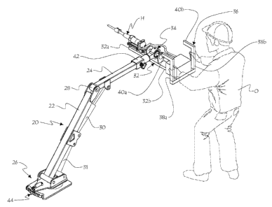
1 ~ Figure 1 is a perspective view of the pneumatic hammer power assist
support device
and associated ground standing articulated positioning arm, with an operator
in
phantom lines operating the pneumatic hammer in a horizontal direction;
figure 2 is a view similar to figure 1, but with the pneumatic hammer being
operated
in an upwardly outwardly inclined direction;
figure 3 is a schematic partial view of the present support device, suggesting
the
omni-directional play afforded by the universal joint forming part of the
pneumatic
hammer support device;
figures 4 and 5 are perspective views at an enlarged scale of the pneumatic
hammer
support device, rotated by half a turn relative to one another;
CA 02415330 2002-12-19
figure & is an exploded view of the upper portion of pneumatic hammer support
device from figure 4;
figure 7 is an exploded view at an enlarged scale of the universal joint
assembly
forming part of the pneumatic hammer support device;
figure 8 is an exploded view of the pivotal joint assembly interconnecting the
pneumatic hammer support device and the ground standing articulated
positioning
arm;
IO
figure 9 is a cross-sectional view at an enlarged scale of the universal joint
assembly
of figure 6; and
figure 10 is an enlarged perspective view of the ,ground foot member from the
articulated positioning arm.
IS
Detailed description of the preferred embodiment
Figures 1 ~ show how the present invention can be handled by an operator O.
A positioning articulated boom 20, defining a lower arm 22 and an upper arm
24, is
pivotally mounted by its lower arm 22 to the ground by a vertical one-axis
pivotal
20 foot mount 25. Lower arm 22 is also tiltable at its lower end portion,
under power
from ram 31 (detailed hereinbelow), Ram means 2 ~', detailed later, releasably
lock
boom 20 against rotation relative to foot 26. Both arms 22 and 24 are pivoted
to one
another about a horizontal one-axis pivot mount 28. Ram means 30, 31, provide
power assist to arms 22 and 24 respectively relative to ground foot mount 26.
Ram
25 means 30, 31, each includes an integral lock valve, to maintain the
Interconnected
structures to their selected relative position. An elongated support 32 is
fiarther
provided, having at an intermediate section thereof a three-axes universal
joint
assembly 34, and carrying at a fore end thereof 32A, a pneumatic hammer H. The
rear end 32B of elongated support 32, opposite fore end 32 A, includes an
integral U-
CA 02415330 2002-12-19
6
shape handle 36. Preferably, each of the two side legs of U-shape handle 36
forms an
integral L-shape as shown, defining upright legs 38A, 38B and two forwardly
directed legs 40A, 40B.
The operator O may grasp with his hands D either the upright legs 38A, 388,
when working generally horizontally against a vertical wall surface with the
hammer
H as shown in figure 1, or the forward legs 40A, 4013, when working in an
inclined
fashion against a generally horizontal (or generally inclined) overlying wall
surface
with the hammer as shown in figure 2. Universal joint assembly 34 is connected
to
the outer end of the boom upper arm 24 by a connector 42 provided with a one
axis
axial rotational mount. With the analogy of a human arm (20), pivot 28 is the
elbow
and universal joint assembly 34, the wrist.
As shown in f gore 8, connector 42 includes a socket 54, having a
I5 mouth 54A opening into a hollow 548. Socket hollow 54B is complementarily
shaped to the outer end portion of boom arm 24, for frictional engagement
therein. A
bolt 56 engages through a bore 58 in the wall of the socket 54, and through a
corresponding bore (not shown) at an end portion of arm 24, and frictionally
engages
the registering section of boom arm 24 to keep it in place and to prevent
accidental
release therefrom. Socket 54 includes an axial projecting threaded shaft 60,
freely
engaged by a sleeve 62.
The hollow 64A of housing 64 receives the combined shaft 60 and
surrounding sleeve 62. Housing 64 is anchored by welding to the casing 66 of
corresponding ball
and socket joint 34 by a nut 68, screwed in place into a connector recess 64B
made in
housing 64 opposite mouth 64C of hollow 64A. Accordingly, housing 64 and
casing
66 can rotate together relative to the socket 54.
CA 02415330 2002-12-19
7
Figures 7 and 9 shovi~ the various components of the universal joint 34 of the
present invention. The casing 66 includes a recessed aperture 70. A
cylindrical
collar 72 with a hemispheric hollow 73 receives therein a spherical ball 74.
The ball
74 is mounted inside collar 72 for free rotation in all directions, but ball
74 is trapped
inside hollow in that it cannot escape unless collar 72 is broken. Such an
assembly of
ball 74 rotatably trapped inside a socket 72 is called a "self alignment
bushing".
Collar 72 is complementarily shaped with recessed aperture 70, so that
friction fit interlock occurs when collar 72 fully engages into housing 66.
Recessed
aperture 70 includes a radially smaller shoulder 70a at one edge thereof,
against
which snugly abuts collar 72. Collar 72 becomes trapped inside housing 66, and
cannot move within the hollow 73 of housing 66, and so collar 72 and housing
66
become integral to one another.
I S A joint shaft 76 extends through joint components 66, 72, 74, with a
radially enlarged intermediate section thereof 78 fitting snugly within the
hollow of
ball 74. A few socket cap screws 80, 80, interlock shaft enlarged portion 78
and ball
74, through threaded bore 78a and counter bore 74a, respectively, so that
shaft 76 and
74 move integrally in unison. Enlarged access ports '72a, 66a, are provided on
collar
72 and housing 66, respectively, to enable Allen key (or the like tool) access
to the
head of the cap screws 80 on shaft portion 78 and ball 74, whenever needed.
Attachment brackets 82, 84, are mounted on opposite sides of ball and
socket joint assembly 66, 72, 74, 76. Bracket member 82 has a small bore 82a
for
free passage of joint shaft inner end portion 76a, while bracket member 84 has
a large
bore 84 to accommodate .passage of enlarged portion 78 of joint shaft 76. The
joint
shaft outer end portion 76b forms a radially enlarged disk.
Joint components 66, 72, 74, 76 are therefore all carried by support bar 32.
CA 02415330 2002-12-19
The size of shaft 76-78, the distance between the two attachment brackets 82,
84, and the size of ball 74 determine the amplitude of movement in space of
the
hammer support 32.
Figures 4-6 show the saddle assembly 86 for attachment of the hammer H to
the outer end portion 32A of support bar 32. Saddle assembly 86 includes a
carriage
88, slidably mounted over bar end portion 32A. Carriage 88 includes a
transverse
downturned bored flange 90, at an inner end thereof, and bar 32 includes an
upturned
bar flange 92, wherein a pair of elongated guide rods !a4, 96, engage at their
opposite
end portions flanges 90 and 92, respectively and a pair of additional bores
82D, 82D,
respectively, of bracket 82. Guide rods 94, 96, guide displacement of carriage
88
slidingly parallel over end portion 32A and retain carriage 88 thereon. A pair
of
saddle members 98, 100, of a shape complementary to the main cylinder housing
C of
hammer H, fixedly anchor the latter to the respective opposite ends of sliding
carriage
88. A pneumatic ram 102 is anchored at an inner end 102A to an intermediate
portion of underface of template 32. A bracket 104A carried at the outer end
of the
piston rod 104 of ram 102, is transversely connected by a link arm 106 to
hammer H,
through ovoidal slot 108 , made in registering portions of bar portion 32A and
carriage 88, respectively.
Control box 48 shown for example in figures 4-6, includes therein a first
electropneumatic valve, which controls the ground base ram 27, a second
electropneumatic valve, which controls the carriage displacement ram 102, a
pneumatic valve which feeds pressurized air fluid to the operating hammer H, a
time
delay circuit, a pressure regulator for carriage ram 102 to adjust the push
bias of the
hammer H against the work surface, and a support electrical circuitry. This
suppot
electrical circuitry is in turn connected to hydraulic valves (not shown)
which are
located at the lower end of boom 22, and these latter valves feed in turn rams
30 and
CA 02415330 2002-12-19
9
31. Alternately, the control unit 48 could be done without and each hydraulic
ram
could be independently actuated manually, in a non electrical fashion, for
example
with a dedicated mechanical joystick.
Foot 26, best illustrated in figure 10, includes a ground engaging plate 116
having a number of notches 118 along an edge portion thereof. A swivel pad 120
with turntable bearings i 21 is pivotally mounted flatly against ground plate
116, for
pivotal motion about a vertical axis. A pivotal assembly 122 is anchored to
swivel
pad 120. Pivotal assembly 122 includes a frame 124 having two parallel pivot
axles
126, 128, extending orthogonally to the vertical pivot axis of swivel pad 120.
The
lower end of boom arm 22 is anchored to pivot axle 126, and the lower end of
ram 31
is anchored to pivot axle 128. Ram 127 is anchored at its cylinder end to a
pivotal
bracket 130, anchored to swivel pad, with the axis of pivot mount 130 parallel
to
pivot axles 126 and 128. The outer end of the piston rod 132 of ram 27 carries
a
pivotal bracket 134, to which is anchored an indexing finger 136. Finger 136
is
adapted to selectively register with one of the notches 118 of ground plate,
when
piston rod 132 is extended from ram 27, once piston rod 132 is retracted into
ram 27.
The air pressurisation constantly biases piston rod 132 to a selected lock
position
inside a notch 118, to counteract the moment of iForce generated by the power
hammer H when striking a work surface.
As shown in figs 2-3, the hammer tool T at the outer end of hammer I-I,
extends generally parallel to support bar 32 and in a direction opposite
operating
handle 36. Tool T is adapted to conventionally strike a work surface, during
operation. Pneumatic power is fed to the cylinder C, for sliding hammer H,
including
integral cylinder Cover support bar 32 backwardly, when not in use, or
forwardly,
CA 02415330 2002-12-19
1
when in use, via pneumatic line 4~ connected to a pneumatic fluid source (not
illustrated). Electrical control of all elements of the present invention is
actuated via
knobs 50 mounted to the legs of the handle 36. knobs 50 control at least one
of the
following:
a) the energizing of the hammer tool T;
b) the sliding fore and aft displacement o f the hammer H;
c) the I -axis pivotal motion of upper boom arm 24 relative to lower boom arm
22;
d) the I-axis pivotal motion of lower boom arm 22 relative to ground foot 26.
e) the control of cylinder 27 on base I20.
In operation, operator O first sends commands by knobs ~0 to hydraulic rams
30 and 31 and to pneumatic cylinder 27, to pivot boom arms 22, 24 and rotate
about
ground pivot assembly 122, so as to bring the hammer H relatively close to the
work
surface area, in a coarse positioning fashion. Then, operator O manually
pushes U-
shape handle 36 to manoever support member ~2 about joints 42 and ~4., to
provide
further fine tuning in the orientation of th,e hammer H relative to the
selected area of
the work surface to be demolished. After that, operator O sends third commands
by
knobs 50 so that pneumatic ram 102 push piston rod 104 forward, to bring the
hammer tool T in engaging contact with the work surface area . Oniy then is
the
hammer H energized to demolish the work surface. Ram I02 maintains its
pressure
on the hammer tool T so that the tool T remains constantly biased against the
work
surface, the work surface area becomes fragmented and progressively
disintegrates.
When hammering work is completed, the operator O sends a final command by
knobs
~0 to de-energize the hammer H and withdraw piston 104 into ram 102, i.e. to
pull
out hammer carriage ~8 .
CA 02415330 2002-12-19
11
The present hammer support and positioner enables a worker to strike with the
hammer tool at work surfaces which are vertical, horizontal or even inclined.
Tools
other than pneumatic hammers could interchangeahly benefit from this self
supporting system, for example, an electric drill, a fluid hose, a firerighter
water hose,
or other heavy tools which must be handled by an operator with some precision
required in targeting. :although mounting to a ground base 1 I6 has been shown
in the
drawings, other types of mounting are not eYCluded. For example, one could
pivotally mount joint 42 to a'oasket, (not shown) wherein arms ?4, 22 and base
?6 are
therefore not needed and removed.