Note: Descriptions are shown in the official language in which they were submitted.
CA 02415463 2003-O1-10
- 1 -
DESCRIPTION
ELASTIC WHEEL
Technical Field
The present invention relates to an elastic wheel for
use as a vehicle wheel, particularly to an elastic wheel
excellent in riding quality,~vibration prevention
performance, sound insulation performance, as well as
steering stability.
Background Art
An elastic wheel substantially comprises a disk to be
fixed on a vehicle axle hub and a rim supporting a tire, and
there have been suggested various elastic wheels each
including a vibration prevention body provided between the
disk and the rim, thus ensuring an improved vibration
prevention performance and an improved riding quality. For
example, Japanese Unexamined Utility Model Registration
Application Publication No. 59-188701 has suggested a wheel,
for use in a tire, using a spring as a vibration preventing
body to improve a vehicle's riding quality.
Further, it is known that rubber can be used as a
vibration preventing body and can be interposed between the
rim and the disk. For example, Japanese Unexamined Utility
Model Registration Application Publication No. 57-73203 has
CA 02415463 2003-O1-10
- 2 -
suggested an elastic wheel in which the rim is connected
with the disk through an elastic body such as rubber.
Moreover, Japanese Unexamined Patent Application Publication
No. 5-338401 has suggested an elastic wheel in which a gap
is formed between the rim and the elastic wheel and such a
gap is then filled in with a vibration preventing rubber.
In addition, W098/33666 has disclosed a wheel/barrier
assembly in which an annular rubber stopper is interposed
between a rim and an inner rim having an identical profile
with the rim.
However, with regard to the aforementioned conventional
elastic wheels in which rubber is used as a vibration
preventing body interposed between the rim and the disk,
since the rubber elastic bodies are respectively fixed
between the inner periphery surface of the rim and the outer
periphery surface of the disk through vulcanization bonding,
although it is possible to exactly control various
vibrations propagating from the rim to the disk through the
rubber elastic bodies in the axial direction and the radial
direction as well as in the rotating direction, there has
been a problem in that it is impossible to control the
displacement of the rubber elastic bodies when there is a
heavy load. Namely, since the cross section of all the
rubber is the same everywhere, it is difficult to obtain an
appropriate vibration prevention performance under all
CA 02415463 2003-O1-10
conditions including a low input and a high input. The same
problem will also occur in an example where a spring is used
as a vibration preventing body.
Moreover, a relationship between the rubber (interposed
between the rim and the disk) and the sound prevention
performance as well as the steering stability has not been
made clear, and there is still a lot which has to be done to
improve the sound insulation performance and the steering
stability.
In view of the above, it is an object of the present
invention to provide an elastic wheel capable improving the
riding quality, the vibration prevention performance and the
sound insulation performance at any time including a low
input and a high input, without hindering durability, safety
and steering stability.
Disclosure of Invention
The inventors of the present invention have conducted
their research repeatedly in order to solve the above-
mentioned problems, while still making use of an advantage
provided by rubber elastic material serving as vibration
preventing means. As a result, it was found that the object
of the present invention can be achieved by the following
manner, thereby accomplishing the present invention. Namely,
an elastic wheel formed according to the present invention
CA 02415463 2003-O1-10
- 4 -
is constituted as follows.
Namely, the present invention is an elastic wheel
comprising a disk, a rim supporting a tire, a pair of guides
annularly fixed on the inner periphery surface of the rim, a
pair of walls annularly (fixed in two side areas along the
wheel axial direction on the outer periphery surface of a
base rim disposed on the disk or on the outer periphery
surface of the disk, and rubber elastic bodies annularly
interposed between the side faces of the guides and the side
faces of the walls, whererin at least one belt is annularly
arranged on the rubber elastic bodies.
Using the above arrangement, it is possible to absorb
vibration by virtue of shear deformation of the installed
rubber elastic bodies, particularly to improve the riding
quality, the vibration prevention performance and the sound
insulation performance when there is a low input. As for
sound insulation performance, the elastic wheel is extremely
effective for sound insulation in high frequency ranges of
100 Hz or more. Further, by making use of the at least one
belt provided on the rubber elastic bodies, it is possible
to obtain a high spring rigidity ratio in the wheel axial
direction and torsional direction with respect to a spring
constant in the wheel eccentric direction, and to obtain a
high steering stability, as compared with a case in which
only the volume of the rubber elastic bodies has been
CA 02415463 2003-O1-10
- 5 -
increased.
Here, with regard to the aforesaid elastic wheel, the
width between the pair of guides in the wheel axial
direction is narrower than the width between the pair of
walls in the wheel axial direction, the inner end portions
of the pair of guides in the wheel radial direction are
combined with each other so as to form a substantially U-
shaped cross section in the wheel axial direction, a rubber
elastic body is annularly disposed on the inner periphery
surface of the substantially U-shaped guide assembly in a
manner such that a gap is formed between the rubber elastic
body and the disk or the outer periphery surface of the base
rim, and is integrally formed with the rubber elastic bodies
annularly interposed between the side faces of the guides
and the side faces of the walls, and the belt is annularly
disposed on the inner periphery surface of the integrally
formed rubber elastic body. Alternatively, the width
between the pair of guides in the wheel axial direction is
larger than the width between the pair of walls in the wheel
axial direction, the outer end portions of the pair of walls
in the wheel radial direction are combined with each other
so as to form an inverted substantially U-shaped cross
section in the wheel axial direction, a rubber elastic body
is annularly disposed on the outer periphery surface of the
inverted substantially U-shaped wall assembly in a manner
CA 02415463 2003-O1-10
- 6 -
such that a gap is formed between the rubber elastic body
and the inner periphery surface of the rim, and is
integrally formed with the rubber elastic bodies interposed
between the side faces of the guides and the side faces of
the walls, and the belt is annularly disposed on the outer
periphery surface of the integrally formed rubber elastic
body. In this way, it is possible to exactly obtain the
aforementioned effects, and to prevent significant
deformation against a high input, by virtue of a compression
action of the rubber elastic bodies disposed on the inner
periphery surface of the substantially U-shaped guide
assembly or on the outer periphery surface of the inverted
substantially U-shaped wall assembly.
Further, with the above elastic wheel, the belt is
preferred to be a steel belt formed by burying steel cords
in rubber. In particular, an introduction angle of the
steel belt is preferred to be substantially a right angle
with respect to the wheel circumferential direction. In
this way, it is possible to exactly obtain the aforesaid
advantage of the present invention, particularly to increase
the spring rigidity ratio in the axial direction.
Furthermore, according to the present invention, there
is provided an elastic wheel comprising a disk, a rim
supporting a tire, a pair of guides annularly fixed on the
inner periphery surface of the rim, a pair of walls
CA 02415463 2003-O1-10
annularly fixed in two side areas along the wheel axial
direction on the outer periphery surface of a base rim
disposed on the disk or on the outer periphery surface of
the disk, and rubber elastic bodies annularly interposed
between the side faces of the guides and the side faces of
the walls, wherein one or both of the side faces on which
the rubber elastic bodies are fixed have uneven portions.
Using the above arrangement, it is possible to absorb
vibration by virtue of shear deformation of the installed
rubber elastic bodies, particularly to improve the riding
quality, the vibration prevention performance and the sound
insulation performance when there is a low input. As for
sound insulation performance, the elastic wheel is extremely
effective for sound insulation in high frequency renges of
100 Hz or more. Further, since uneven portions are formed
on the surfaces on which rubber elastic bodies are fixed, an
entire bonding area can be increased. Therefore, as
compared with an example in which rubber elastic body
bonding surfaces are flat, it is allowed to more firmly fix
the rubber elastic bodies and to increase a wheel torsional
rigidity, thus improving a steering stability.
Here, the aforesaid uneven portions are preferred to be
in a corrugated form. In this way, it is possible to
exactly obtain the aforesaid effects, without bringing about
any damage to the guides with which the rubber elastic
CA 02415463 2003-O1-10
bodies are fixed, and without damaging the strength of the
walls. Moreover, it is possible to inhibit a rigidity
rising in the vertical direction of the wheel and to
maintain good sound insulation performance and good riding
quality. Further, it is preferable that the aforesaid
uneven portions be formed on both of every two mutually
facing side faces on which the rubber elastic bodies are to
be fixed, and that uneven portions formed on every two
mutually facing side faces be complementary to each other.
Therefore, it is possible to more exactly affect a shear
deformation of the rubber elastic bodies and thus more
exactly obtain the aforesaid advantages. In addition, it is
possible to reduce the rigidity in the wheel vertical
direction and to ensure a uniform rigidity in the wheel
circumferential direction. Moreover, with the above-
descried elastic wheel, the width between the pair of guides
in the wheel axial direction is narrower than the width
between the pair of walls in the wheel axial direction, the
inner end portions of the pair of guides in the wheel radial
direction are combined with each other so as to form a
substantially U-shaped cross section in the wheel axial
direction, a rubber elastic body is annularly interposed
between the inner periphery surface of the substantially U-
shaped guide assembly and the disk or the outer periphery
surface of the base rim, in a manner such that a gap is
CA 02415463 2003-O1-10
- 9 -
formed between the rubber elastic body and one of said
periphery surfaces. Alternatively, the width between the
pair of guides in the wheel axial direction is larger than
the width between the pair of walls in the wheel axial
direction, the outer end portions of the pair of guides in
the wheel radial direction are combined with each other so
as to form an inverted substantially U-shaped cross section
in the wheel axial direction, a rubber elastic body is
annularly interposed between the outer periphery surface of
the inverted substantially U-shaped guide assembly and the
inner periphery surface of the rim, in a manner such that a
gap is formed between the rubber elastic body and one of
said periphery surfaces. In this way, it is possible to
exactly obtain the aforesaid effects and to prevent some
significant deformation possibly caused by a high input, by
virtue of a compressing action produced by the rubber
elastic bodies disposed on the outer periphery surface of
the base rim or on the inner periphery surface of the rim.
Furthermore, according to the present invention, there
is provided an elastic wheel comprising a disk, a rim
supporting a tire, a pair of guides annularly fixed on the
inner periphery surface of the rim, a pair of walls
annularly fixed in two side areas along the wheel axial
direction on the outer periphery surface of a base rim
disposed on the disk or on the outer periphery surface of
CA 02415463 2003-O1-10
- 1~ -
the disk, and rubber elastic bodies annularly interposed
between the side faces of the guides and the side faces of
the walls, wherein the width between the pair of guides in
the wheel axial direction is' narrower than the width between
the pair of walls in the wheel axial direction, the inner
end portions of the pair of guides in the wheel radial
direction are combined with each other so as to form a
substantially U-shaped cross section in the wheel axial
direction, a rubber elastic body is annularly disposed on
the inner periphery surface of the substantially U-shaped
guide assembly in a manner such that a gap is formed between
the rubber elastic body and the disk or the outer periphery
surface of the base rim, and is integrally formed with the
rubber elastic bodies annularly interposed between the side
faces of the guides and the side faces of the walls. In
particular, a spring is wound within the integrally formed
rubber elastic body along the wheel circumferential
direction. Alternatively, there is provided an elastic
wheel comprising a disk, a rim supporting a tire, a pair of
walls annularly fixed on the outer periphery surface of a
base rim disposed on the disk or on the outer periphery
surface of the disk, a pair of guides annularly fixed in two
side areas along the wheel axial direction on the inner
periphery surface of the rim, and rubber elastic bodies
annularly interposed between the side faces of the guides
CA 02415463 2003-O1-10
- 11
and the side faces of the walls, wherein the width between
the pair of guides in the wheel axial direction is larger
than the width between the pair of walls in the wheel axial
direction, the outer end portions of the pair of walls in
the wheel radial direction are combined with each other so
as to form an inverted substantially U-shaped cross section
in the wheel axial direction, a rubber elastic body is
annularly disposed on the outer periphery surface of the
inverted substantially U-shaped guide assembly in a manner
such that a gap is formed between the rubber elastic body
and the inner periphery surface of the rim, and is
integrally formed with the rubber elastic bodies annularly
interposed between the side faces of the guides and the side
faces of the walls. In particular, a spring is wound within
the integrally formed rubber elastic body in the wheel
circumferential direction.
By virtue of the above arrangement, it is possible to
absorb vibration by virtue of shear deformation of the
installed rubber elastic bodies, particularly to improve the
riding quality, the vibration prevention performance and the
sound insulation performance when there is a low input.
Meanwhile, by virtue of an action of the spring imbedded in
the rubber elastic bodies, it is possible to provide a
higher wheel rigidity in the lateral and circumferential
directions than in the vertical direction, thereby improving
CA 02415463 2003-O1-10
- 12 -
the steering stability. Further, as for sound insulation
performance, the elastic wheel is extremely effective for
sound insulation in high frequency ranges of 100 Hz or more.
Here, with regard to the above-described elastic wheel,
it is preferable that the spring be wound within each rubber
elastic body, covering the entire width of each rubber
elastic body in the wheel axial direction. In this way, it
is possible to uniformly increase a resistance against the
load on each rubber elastic body, thereby making it possible
to best obtain the above-discussed advantages. Further, it
is preferable that the number of windings of the spring be 2
- 9 for every 10 mm of width in the wheel axial direction,
while the cross section area of the steel wire forming the
spring is preferred to be 0.8 - 7 mm2. By virtue of this,
it is possible to optimize the spring which is to be
imbedded in rubber, thereby making it possible to properly
adjust the rigidity. Besides, it is also possible for the
cross section of the steel wire forming the spring to be
made rectangular, thereby effectively ensuring an advantage
of improving the rigidity.
Brief Description of the Drawings
Fig. 1 is a partially enlarged sectional view of an
elastic wheel according to one embodiment of the present
invention.
CA 02415463 2003-O1-10
- 13 -
Fig. 2 is an enlarged view showing one part of the
wheel illustrated in Fig. 1.
Fig. 3 is a partially enlarged sectional view of an
elastic wheel according to another embodiment of the present
invention.
Fig. 4 is a partially enlarged sectional view of an
elastic wheel according to a further embodiment of the
present invention.
Fig. 5 provides several cross sectional views taken
along line A - A in Fig. 4.
Fig. 6 is a partially enlarged sectional view of an
elastic wheel according to a still further embodiment of the
present invention.
Fig. 7 shows several cross sectional views taken along
line B - B in Fig. 6.
Fig. 8 is a partially enlarged sectional view of an
elastic wheel according to one more embodiment of the
present invention.
Fig. 9 is a partially enlarged sectional view of an
elastic wheel according to one more embodiment of the
present invention.
Fig. 10 is a partially enlarged sectional view of an
elastic wheel according to one more embodiment of the
present invention.
CA 02415463 2003-O1-10
- 14 -
Best Mode for Carrying Out the Invention
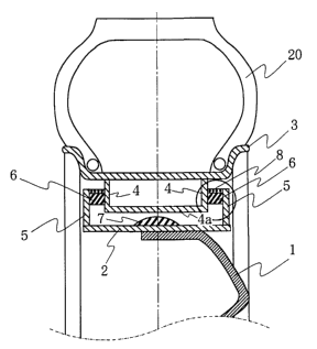
As shown in Fig. 1, an elastic wheel according to one
embodiment of the present invention is formed such that a
disk 1 to be fixed on an axle hub (not shown) has a base rim
2. Here, the disk 1 and the base rim 2 are integrally
formed together by means of molding. Alternatively, it is
possible to use a spoke wheel or a mesh wheel combined with
a supporting body such as a spoke or mesh. In practice, a
material forming the disk 1 may be any one of steel,
aluminum, magnesium and synthetic resin. However, if it is
desired to obtain a vehicle wheel light in weight, it is
preferable to use aluminum or synthetic resin.
In addition, a pair of guides 4 are annularly fixed on
the inner periphery surface of a rim 3 supporting a tire 20,
while the end portions of the pair of guides 4 in the radial
direction of the wheel are combined with each other, in a
manner such that a substantially U-shaped cross section is
formed in the wheel axial direction. In this way, the pair
of guides 4, by forming the substantially U-shaped cross
section in the wheel axial direction, can function as a
stopper in cooperation with the inner periphery surface 4a
formed by the guides as well as a rubber elastic body 7
which will be described later, thereby making it possible to
deal with a large input. The shape of the rim 3 should not
be limited, but is selectable depending upon its actual use.
CA 02415463 2003-O1-10
- 15 -
In fact, it is allowed to employ those not belonging to
standardized products, such as a rim whose diameters at
their end portions are different from each other. Besides,
it is possible for the pair of guides 4 to be formed by
causing the cross section of the rim 3 in the wheel axial
direction to display a recess portion, i.e., to protrude
inwardly in the wheel radial direction.
Furthermore, a pair of walls 5 are annularly fixed on
the outer periphery surface of the base rim 2 at two ends in
the axial direction, in a manner such that the width between
the walls is larger than the width between the guides 4 in
the wheel axial direction. Between the two outer surfaces
of the two guides 4 and the two inner surfaces of the two
walls 5, there are annularly provided rubber elastic bodies
6 which are fixed therein through a bonding process such as
vulcanization bonding, while belts 8 are disposed on the
outer periphery surfaces of the rubber elastic bodies 6, as
shown in an enlarged view of Fig. 2.
However, the position of the belts 8 in the present
invention does not have to be limited to the outer periphery
surfaces of the rubber elastic bodies 6. In fact, it is
possible for the belts 8 to be disposed on the inner surface
of the rubber elastic bodies 6. Moreover, such rubber
elastic bodies are also allowed to be disposed on both the
upper and lower surfaces of the belts 8. In addition,
CA 02415463 2003-O1-10
- 16 -
although the present embodiment shown in the drawing
indicates that the belts 8 are disposed to cover the whole
width of the rubber elastic bodies 6 in the wheel axial
direction, it is also allowable for the belts 8 to cover
only part of the rubber elastic bodies 6 to obtain the
similar effect. Furthermore, since a rising rate of a
spring rigidity ratio in the wheel axial direction and the
wheel torsional direction will be different depending upon
an angle at which cords are introduced into the belts 8, it
is preferable to select an appropriate angle for introducing
the cords into the belts 8, in accordance with an actual use.
Besides, the belts 8 do not have to be limited to only one
layer, but is allowed to be in a multiple form including a
plurality of belts laminated one above another. At this
time, if a plurality of belts are arranged in a manner such
that cords 9 imbedded within these belts intersect one
another, it is possible to properly increase the spring
rigidity ratio in the wheel axial direction and the wheel
torsional direction.
The belt 8 suitable for use in the present invention is
allowed to be the same as that used in a radial tire or the
like. For example, as the reinforcing cords 9, it is
possible to use not only steel cords, but also organic fiber
cords such as aramid fiber cords. Further, the number of
cords to be introduced into each belt may also be in the
CA 02415463 2003-O1-10
- 17 -
same range usually for use in a radial tire or the like.
Moreover, although there is no particular limitation to a
covering rubber 10 forming the belt, it is preferable for
the covering rubber 10 to be formed by the same rubber used
in forming the rubber elastic bodies 6, or to be formed by a
rubber having a good adhesion with the rubber elastic bodies
6.
In the preferred embodiment shown in Fig. 1, another
rubber elastic body 7 is annularly interposed between the
inner periphery surface 4a formed by the guides 4 and the
outer periphery surface of the base rim 2. Such rubber
elastic body 7 is bonded to the outer periphery surface of
the base rim 2, through a bonding process such as
vulcanization bonding, with a gap formed between the rubber
elastic body and the inner periphery surface 4a formed by
the guides 4. Alternatively, the rubber elastic body 7 may
be bonded to the inner periphery surface 4a formed by the
guides 4, while a gap is formed between the rubber elastic
body and the outer periphery surface of the base rim 2.
Next, a description will be given to explain an elastic
wheel formed according to another embodiment of the present
invention. This preferred embodiment, as shown in Fig. 3,
is formed such that a width between the pair of walls 5 in
the wheel axial direction, which are fixedly provided on
both sides of the outer periphery surface of the base rim 2,
CA 02415463 2003-O1-10
18
in the aspects of flavor and taste.
Conforming to the foregoing Tasting Test Example, Example 4 of
mayonnaise type, Comparative Example 1 using soybean milk at ordinary
concentration (Brix concentration 12) instead of concentrated soybean milk,
and reference of commercial mayonnaise were selected, and the body forming
property was comparatively studied.
The mayonnaise-like food was changed in a tube container, and squeezed
into a conical form of 4 cm in bottom diameter and about 4 cm in height (to
about second joint of index finger), and collapse of this conical form in 30
minutes at room temperature was observed, and the body forming property of
each sample was judged by the conical height retention rate expressed in the
following formula.
Conical height retention rate (%)
= (conical height in 30 minutes/initial height) x 100
In the evaluation of this Test Example, the higher conical height
retention rate of sample means a better body forming property, and the lower
rate means an inferior body forming property.
Test results are shown below.
Example 4 CEm~ple 1e Reference
Conical height g6% 74% 88%
retention rate
According to the results, the mayonnaise-like food of Example 4 was very
high in the retention rate, and was superior to the reference in that the
shape
can be held softly and firml and an excellent bod formin
y, y g property was
CA 02415463 2003-O1-10
- 19 -
vibration prevention performance and sound insulation
performance, by virtue of a shearing action provided by the
rubber elastic body 6. Moreover, even when an input becomes
large, it is still possible to prevent a significant
distortion by virtue of a compression action of the rubber
elastic body 6 located above the outer periphery surface 5a.
Furthermore, in the preferred embodiment shown in Fig.
3, the belt 8 is disposed on the outer periphery surface of
the rubber elastic body 6 integrally formed between the pair
of guides 4. The structure and the arrangement of the belt
8 may be properly selected in the same manner as described
above depending on how it will be used. In this way, it is
possible to obtain the vibration prevention effect and the
sound insulation effect, as well as the desired steering
stability.
A further elastic wheel formed according to a further
embodiment of the present invention shown in Fig. 4 is
formed such that a disk 101 to be fixed on an axle hub (not
shown) has a base rim 102. Here, the disk 101 and the base
rim 102 may be integrally formed together by means of
molding. Alternatively, it is possible to use a spoke wheel
or a mesh wheel combined with a supporting body such as a
spoke or mesh. In practice, a material forming the disk 101
may be any one of steel, aluminum, magnesium and synthetic
resin. However, if it is desired to obtain a vehicle wheel
CA 02415463 2003-O1-10
- 20 -
light in weight, it is preferable to use aluminum or
synthetic resin.
In addition, a pair of guides 104 are annularly fixed
on the inner periphery surface of a rim 103 supporting a
tire 120, while the end portions of the pair of guides 104
in the radial direction of the wheel are combined with each
other, in a manner such that a substantially U-shaped cross
section is formed in the wheel axial direction. In this way,
the pair of guides 104, by forming the substantially U-
shaped cross section in the wheel axial direction, can
function as a stopper in cooperation with the inner
periphery surface 104a formed by the guides as well as a
rubber elastic body 107 which will be described later,
thereby enabling them to deal with a large input. The shape
of the rim 103 should not be limited, but is selectable
depending upon its actual use. In fact, it is allowed to
employ those not belonging to standardized products, such as
a rim whose diameters at their end portions are different
from each other. Besides, it is also possible for the pair
of guides 104 to be formed by causing the cross section of
the rim 103 in the wheel axial direction to display a recess
portion, i.e., to protrude inwardly in the wheel radial
direction.
Furthermore, a pair of walls 105 are annularly fixed on
the outer periphery surface of the base rim 102 at two ends
CA 02415463 2003-O1-10
- 21 -
in the axial direction, in a manner such that the width
between the walls is larger than the width between the
guides 104 in the wheel axial direction. Between the two
outer surfaces of the two guides 104 and the two inner
surfaces of the two walls 105, there are annularly provided
rubber elastic bodies 106 bonded therein through a bonding
process such as vulcanization bonding.
In the present invention, it is important that the two
outer surfaces of the two guides 104 and the two inner
surfaces of the two walls 105 be formed into uneven surfaces ,
so that total bonding area between these surfaces and the
rubber elastic bodies can be increased as compared with the
case in which these surfaces are flat, thereby making it
possible to more firmly fix the rubber elastic bodies
through a bonding process such as vulcanization bonding. On
the other hand, although there is no limitation to the shape
of the uneven surfaces, it is preferable to form corrugated
surfaces since a corrugated surface is easy to form and can
offer a satisfactory strength. In more detail, it is
possible to form the uneven surfaces as shown in Figs. 5(a)
- 5(d) which are circumferentially sectional views taken
along line A - A in Fig. 4. At this time, it is preferable
that the uneven portions of every two mutually facing uneven
surfaces be made complementary to each other, so that it is
possible to effectively obtain a desired shear deformation
CA 02415463 2003-O1-10
- 22 -
of the rubber elastic bodies 106, thereby inhibiting an
undesired rising of the rigidity of the wheel in the
vertical direction, and also prohibiting an non-uniform
rigidity in the circumferential direction. However, where
the uneven portions are those shown in Fig. 5(d), it is
preferable that such uneven portions be provided in several
positions at an equal interval in the circumferential
direction, more preferably in 6 - 8 positions.
In the preferred embodiment shown in Fig. 4, another
rubber elastic body 107 is annularly interposed between the
inner periphery surface 104a formed by the guides 104 and
the outer periphery surface of the base rim 102. Such a
rubber elastic body 107 is bonded to the outer periphery
surface of the base rim 102, through a bonding process such
as vulcanization bonding, with a gap formed between the
rubber elastic body and the inner periphery surface 104a
formed by the guides 104. Alternatively, the rubber elastic
body 107 may be bonded to the inner periphery surface 104a
formed by the guides 104, while a gap is formed between the
rubber elastic body and the outer periphery surface of the
base rim 102.
In the following, a description will be given to
explain an elastic wheel formed according to a still further
embodiment of the present invention. This preferred
embodiment, as shown in Fig. 6, is such that a width between
CA 02415463 2003-O1-10
- 23 -
the pair of walls 105 in the wheel axial direction, which
are fixedly provided on both sides of the outer periphery
surface of the base rim 102, is narrower than the width
between the pair of guides 104 in the wheel axial direction.
At this time, the rubber elastic bodies 106 are annually
attached between the two inner surfaces of the guides 104
and the two outer surfaces of the walls 105. Further, the
outer end portions of the pair of walls 105 in the wheel
radial direction are integrally combined together in a
manner shown in the drawing, so that an inverted
substantially U-shaped cross section is formed in the wheel
axial direction. Moreover, a rubber elastic body 106
serving as stopper is provided also between the outer
periphery surface 105a formed by the walls 105 and the inner
surface of the rim 103. Here, the walls 105 can also be
directly provided on the outer periphery surface of the disk
101. For example, although not shown in the drawing, the
walls 105 may be provided by annularly forming projections
in the circumferential direction on the outer periphery
surface of the disk 101.
A method of annularly attaching the rubber elastic body
may be carried out in the following manner. For example,
the rubber elastic body is bonded to the inner periphery
surface of the rim 103, in a manner such that a gap is
formed between the rubber elastic body and the outer
CA 02415463 2003-O1-10
- 24 -
periphery surface 105a. Alternatively, the rubber elastic
body is bonded to the outer periphery surface 105a, in a
manner such that a gap is formed between the rubber elastic
body and the inner periphery surface of the rim 103. In
addition, it is also possible to use another method shown in
Fig. 6. Namely, a pair of rubber elastic bodies 106 may be
disposed to extend above the outer periphery surfaces 105a
and are combined together so as to form an integral body,
thereby providing a function as a stopper. In this way, it
is possible to obtain the exact same effect as obtainable
from the elastic wheel shown in Fig. 4 illustrating a
preferred embodiment of the present invention. This means
that it is possible to sufficiently improve the riding
quality, the vibration prevention performance and the sound
insulation performance by virtue of the rubber elastic body
106, provided that an input is not extremely large. Further,
even if an input becomes large, it is still possible to
prevent a significant distortion by virtue of a compression
action produced by the rubber elastic body 106 located above
the outer periphery surfaces 105a.
In the present invention, it is important that at least
the two inner surfaces of the two guides 104 be formed into
uneven surfaces. In fact, it is possible to form the uneven
surfaces as shown in Figs. 7(a) and 7(b) which are
circumferentially sectional views taken along line B - B in
CA 02415463 2003-O1-10
- 25 -
Fig. 6. In Fig. 7(a), the two inner surfaces of the two
guides 104 are formed into uneven surfaces, while the outer
surfaces of the walls 105 are kept in their original flat
state. On the other hand, in Fig. 7(b), both the inner
surfaces of the guides 104 and the outer surfaces of the
walls 105 have been formed into uneven surfaces. Actually,
similar to the above-described preferred embodiments, there
should not be any limitation to the shape of the uneven
surfaces .
An elastic wheel according to a still further
embodiment of the present invention shown in Fig. 8 is
formed such that a disk 201 to be fixed on an axle hub (not
shown) has a base rim 202. Here, the disk 201 and the base
rim 202 may be integrally formed together by means of
molding, as shown in Fig. 9 and Fig. 10. Alternatively, it
is possible to use a spoke wheel or a mesh wheel combined
with a supporting body such as a spoke or mesh. In practice,
a material forming the disk 201 may be any one of steel,
aluminum, magnesium and synthetic resin. However, if it is
desired to obtain a vehicle wheel light in weight, it is
preferable to use aluminum or synthetic resin.
Further, a pair of guides 204 are annularly fixed on
the inner periphery surface of a rim 203 supporting a tire
220, on both sides of the wheel axial direction. The shape
of the rim 203 should not be limited, but is selectable
CA 02415463 2003-O1-10
- 26 -
depending upon its actual use. In fact, it is allowed to
employ those not listed in the standardized products, such
as a rim whose diameters at their end portions are different
from each other. Besides, it is also possible for the pair
of guides 204 to be formed by causing the cross section of
the rim 203 in the wheel axial direction to display a recess
portion, i.e., to protrude inwardly in the wheel radial
direction.
Furthermore, a pair of walls 205 are annularly fixed on
the outer periphery surface of the base rim 202, in a manner
such that a width between the pair of walls 205 is narrower
than the width between the guides 204 in the wheel axial
direction. The outer end portions of the pair of walls 205
in the radial direction of the wheel are combined with each
other, in a manner such that an inverted substantially U-
shaped cross section is formed in the wheel axial direction.
Between the two inner surfaces of the two guides 204 and the
two outer surfaces of the two walls 205, there is annularly
provided a rubber elastic body 206 bonded therein through a
bonding process such as vulcanization bonding. The rubber
elastic body 206, as shown in the drawing, is extending to
the outer periphery surface of the substantially U-shaped
configuration formed between the walls 205. In fact, the
rubber elastic body 206 is interposed in a manner such that
a gap is formed between the rubber body and the inner
CA 02415463 2003-O1-10
- 27 -
periphery surface of the rim 203, thereby serving as a
stopper for dealing with a high input. Moreover, the walls
205, as shown in Fig. 9 and Fig. 10, can also be formed by
annularly providing a projection on the outer periphery
surface of the disk 201.
In the preferred embodiment shown in Fig. 8, the
integrally formed rubber elastic body 206 is interposed
between the pair of guides 204, while a spring 207 is buried
within the rubber elastic body 206 in the circumferential
direction of the wheel. With the use of the spring 207, it
is possible to obtain a higher rigidity in the
circumferential direction than in the vertical direction.
Therefore, apart from an effect of improving the riding
quality, the vibration prevention performance and the sound
insulation performance, all by absorbing vibration using the
shear deformation of the rubber elastic body 206, it is also
possible to obtain an improved steering stability. In this
way, with the use of the present invention, it becomes
possible to improve various performances, dealing with
various inputs including a low input and a high input.
On the other hand, in contrast to the present
embodiment shown in the drawing, if the width between the
pair of the guides 204 in the wheel axial direction, fixed
on the inner periphery surface of the rim 203, is narrower
than the width between the pair of walls 205 in the wheel
CA 02415463 2003-O1-10
- 28 -
axial direction, and if the inner end portions of the guides
204 in the wheel radial direction are combined with each
other to form a substantially U-shaped cross section in the
wheel axial direction, the rubber elastic body 206 should be
interposed between the two outer surfaces of the two guides
204 and the two inner surfaces formed of the two walls 205,
and are allowed to extend to the inner surface formed by the
guides 204 in the U-shaped configuration, with a gap formed
between the rubber elastic body 206 and the outer periphery
surface of the base rim 202. At this time, by burying the
spring 207 in the rubber elastic body 206 interposed between
the pair of the walls 205, it is possible to obtain the same
effects as obtainable in the above-described embodiments.
The specifications, arrangement and number of layers of
the spring 207 should not be limited, but can be properly
selected so as to obtain a desired rigidity. Specifically,
in order to obtain an effect of uniformly improving rigidity
with respect to a load on the rubber elastic body 206, it is
preferable for the spring 207 to be uniformly wound within
the rubber elastic body 206, covering the entire width of
the rubber elastic bodies in the wheel axial direction. On
the other hand, as shown in Fig. 10, the spring 207 may be
disposed only in both side areas of the rubber elastic body
206, since the disk 201 which is integrally formed with the
base rim 202 and the walls 205, is not present in these side
CA 02415463 2003-O1-10
- 29 -
areas over the width in the wheel axial direction. As a
spring for use in the present embodiment, it is preferable
to employ one whose number of windings is 2 - 9 for every 10
mm of width in the wheel axial direction. Further, in order
to ensure an effect of improving rigidity, the cross section
of a steel wire forming the spring is preferred to be
rectangular (shown in Fig. 9), rather than circular (shown
in Fig. 8 and Fig. 10). However, by using such a spring, it
is slightly difficult to provide a desired durability
against fatigue. Moreover, the cross sectional area of the
steel wire is preferred to be 0.8 - 7 mmz.
In the preferred embodiments shown in Figs. 8 - 10, the
rubber elastic body 206 is interposed to extend from between
the two outer surfaces of the inverted substantially U-
shaped wall assembly 205 and the two inner surfaces of the
guides 204, to the outer periphery surface of the inverted
substantially U-shaped wall assembly 205. As a result, when
an input becomes high, a stopper function will act between
the outer periphery surfaces of the walls 205 and the inner
periphery surface of the rim 203. On the other hand, when
an input is not extremely high, it is possible to
sufficiently improve the riding quality, the vibration
prevention performance and the sound insulation performance
by virtue of a shearing action of the rubber elastic body
206 interposed between the walls 205 and the guides 204.
CA 02415463 2003-O1-10
- 30 -
Moreover, it is also possible to prevent a significant
deformation by virtue of a compression action produced by
the rubber elastic body 206.
The rubber elastic bodies used in the present invention
may be those well known as vibration prevention rubbers, and
can be prepared by mixing an appropriate additive into a
natural rubber or a synthetic rubber. Here, a natural
rubber or a synthetic rubber may be a diene rubber such as
butadiene rubber, styrene-butadiene copolymer rubber and
butyl rubber, while an additive may be sulfur, a
vulcanization accelerator, an antioxidant or carbon black.
JIS-A hardness (Hd) of each rubber elastic body is preferred
to be 30 - 80° in order to ensure a satisfactory vibration
absorbing performance and a satisfactory durability, while
its elastic modulus is 1 x 10' - 105 N/cm2.
Next, the present invention will be further described
through several examples.
Example 1
An elastic wheel having a structure shown in Fig. 3 was
fabricated under the following conditions.
(rim)
size: 15 in
width: 5.5 J
(rubber elastic bodies)
CA 02415463 2003-O1-10
- 31 -
dimension: vertical size: 11 mm; longitudinal size:
15 mm
JIS-A hardness: 60°
elastic modulus: 4 x 10⁴ N/cm2
distance between the ri.m and the base rim in wheel
radial direction: 25 mm
distance between the outer periphery surface of the
rubber elastic body 6 and the inner periphery surface of the
rim 3: 6 mm
(belt)
number of belts: 1
cord: steel cord (1 x 5 x 0.23 (mm))
cord introducing angle: 90° with respect to the
circumferential direction
number of introduced cords: 36 lengths/50 mm
imbedded rubber: the same as the above-described
rubber elastic bodies.
Example 2
An elastic wheel was fabricated in the same manner as
in Example 1, except that an angle for introducing cords
into the belt 8 is 45° with respect to the circumferential
direction.
Example 3
CA 02415463 2003-O1-10
- 32 -
An elastic wheel was fabricated in the same manner as
in Example 1, except that an angle for introducing cords
into the belt is 0° with respect to the circumferential
direction.
Comparative Example 1
An elastic wheel was fabricated in the same manner in
Example 1, except that the belt 8 was not used.
The elastic wheels fabricated in Examples 1 - 3 and
Comparative Example 1 were tested to measure the respective
constants of vertical springs in elastic portions, springs
in the wheel axial direction and torsional springs, with the
results shown in Table 1.
Table 1
Example Example Example Comparative
1 2 3
Example 1
Vertical spring 201 235 174 158 (1)
(kgf/mm)
Axial spring 1161 907 888 801
(kgf/mm)
Torsional spring 831 1260 837 744
102 (kgf~mm/ )
Tires having a size of 185/55815 were attached to the
elastic wheels obtained in Examples 1 - 3 as well as in
Comparative Example 1, and their steering stabilities were
CA 02415463 2003-O1-10
- 33 -
evaluated. It was confirmed that any one of the rubber
elastic wheels obtained in any one of the above Examples
could provide a more satisfactory steering stability than
the elastic wheel obtained in the Comparative Example 1.
However, it was found that the elastic wheels obtained in
both Examples and the Comparative Example could absorb
vibration by virtue of shear deformation of the rubber
elastic bodies when an input was low, and could inhibit a
significant distortion by virtue of a compression input from
one rubber elastic body when an input was higher. Further,
it was understood from the result of a test on a sound
insulation performance that these elastic wheels were
extremely effective for sound insulation in high frequency
ranges of 100 Hz or more.
Example 4
Under the following conditions, an elastic wheel was
fabricated which has a structure shown in Fig. 6 and in
which rubber elastic bodies having a configuration shown in
Fig. 7(a) have been annularly attached. A tire having a
size of 185/55815 was attached to the elastic wheel obtained
in this Example, and its vibration absorbing stability,
sound insulation performance and durability were evaluated.
(rim)
size: 15 in
CA 02415463 2003-O1-10
- 34 -
width: 5.5 J
(rubber elastic bodies)
dimension: vertical size: 11 mm; longitudinal size:
15 mm
JIS-A hardness: 60°
elastic modulus: 4 x 10° N/cmz
distance between the rim and the base rim in wheel
radial direction: 25 mm
distance between the outer periphery surface of the
rubber elastic body 106 and the inner periphery surface of
the rim 103: 6 mm
Comparative Example 2
For the purpose of comparison, another elastic wheel
was fabricated in the same method as in the above Examples,
except that the inner surfaces of the guides 104 and the two
outer surfaces of the walls 105 were all flat.
It was confirmed that the elastic wheels obtained in
both Example 4 and Comparative Example 2 can all absorb
vibration by virtue of shear deformation of rubber elastic
bodies when an input is low, and can also inhibit a
significant distortion by virtue of a compression input from
one rubber elastic body when an input is large. It was also
confirmed that the rubber elastic body 106 in Example 4 can
be more firmly fixed on the two inner surfaces of the guides
CA 02415463 2003-O1-10
- 35 -
104 than the rubber elastic body in Comparative Example 2.
In addition, it was found that the elastic wheel in Example
4 can offer more satisfactory steering stability and riding
quality than the elastic wheel in Comparative Example 2.
Moreover, it was understood from the result of a test on a
sound insulation performance that the elastic wheels
obtained in both Example 4 and Comparative Example 2 are
extremely effective for sound insulation in high frequency
renges of 100 Hz or more.
Industrial Applicability
As described above, with the use of the elastic wheel
formed according to the present invention, it is possible to
improve the riding quality, the vibration prevention
performance and the sound insulation performance at any time
including a low input and a high input, without hindering
durability, safety and steering stability.