Language selection

Search

Patent 2415509 Summary

Third-party information liability

Some of the information on this Web page has been provided by external sources. The Government of Canada is not responsible for the accuracy, reliability or currency of the information supplied by external sources. Users wishing to rely upon this information should consult directly with the source of the information. Content provided by external sources is not subject to official languages, privacy and accessibility requirements.

Claims and Abstract availability

Any discrepancies in the text and image of the Claims and Abstract are due to differing posting times. Text of the Claims and Abstract are posted:

  • At the time the application is open to public inspection;
  • At the time of issue of the patent (grant).
(12) Patent Application: (11) CA 2415509
(54) English Title: BALLAST FOR A LAMP AND METHOD FOR OPERATING A BALLAST FOR A LAMP
(54) French Title: BALLAST POUR LAMPE ET METHODE D'UTILISATION D'UN BALLAST POUR LAMPE
Status: Deemed Abandoned and Beyond the Period of Reinstatement - Pending Response to Notice of Disregarded Communication
Bibliographic Data
(51) International Patent Classification (IPC):
  • H05B 41/36 (2006.01)
  • H05B 41/38 (2006.01)
  • H05B 41/392 (2006.01)
(72) Inventors :
  • BUSSE, OLAF (Germany)
  • HECKMANN, MARKUS (Germany)
  • SOWA, WOLFRAM (Germany)
(73) Owners :
  • PATENT-TREUHAND-GESELLSCHAFT FUER ELEKTRISCHE GLUEHLAMPEN MBH
(71) Applicants :
  • PATENT-TREUHAND-GESELLSCHAFT FUER ELEKTRISCHE GLUEHLAMPEN MBH (Germany)
(74) Agent: SMART & BIGGAR LP
(74) Associate agent:
(45) Issued:
(22) Filed Date: 2002-12-30
(41) Open to Public Inspection: 2003-07-02
Availability of licence: N/A
Dedicated to the Public: N/A
(25) Language of filing: English

Patent Cooperation Treaty (PCT): No

(30) Application Priority Data:
Application No. Country/Territory Date
102 00 047.6 (Germany) 2002-01-02

Abstracts

English Abstract


The invention relates to a ballast for a lamp having an
inverter which comprises at least one switch (S1; S2),
and having a drive circuit (10) for alternately opening
and closing the at least one switch (S1; S2) wherein
the drive circuit (10) is designed to drive the at
least one switch (S1; S2) alternately at at least two
different frequencies (.omega.a, .omega.b). It also relates to a
method for operating a ballast for a lamp having an
inverter which comprises at least one switch (S1; S2),
and having a drive circuit (10) for alternately opening
and closing the at least one switch (S1; S2) wherein
the drive circuit drives the at least one switch (S1;
S2) alternately at at lease two different frequencies
(.omega.a, .omega.b)


Claims

Note: Claims are shown in the official language in which they were submitted.

Claims
1. A ballast for a lamp having an inverter which
comprises at least one switch (S1; S2), and having
a drive circuit (10) for alternately opening and
closing the at least one switch (S1; S2)
characterized
in that the drive circuit (10) is designed to
drive the at least one switch (S1; S2) alternately
at at least two different frequencies (.omega.a, .omega.b).
2. The ballast as claimed in claim 1,
characterised
in that the drive circuit (10) is designed to
change between the different drive frequencies
(.omega.a, .omega.b) at a switching frequency which is chosen
such that the different brightnesses of the lamp
(La), which are correlated with the different
drive frequencies (.omega.a, .omega.b), can no longer be
resolved by a human eye.
3. The ballast as claimed in claim 2,
characterized
in that the switching frequency is at least 60 Hz,
in particular at least 80 Hz.
4. The ballast as claimed in one of the preceding
claims,
characterized
in that a mains rectifier is connected upstream of
the inverter arid can be fed from an AC voltage
network which is at a mains frequency, with the
switching frequency being synchronized to the
mains frequency.
5. The ballast as claimed in claim 4,
characterized

in that the mains frequency is 50 Hz and the
switching frequency is a multiple of 50 Hz, in
particular 100 Hz.
6. The ballast as claimed in claim 4,
characterized
in that the mains frequency is 60 Hz and the
switching frequency is a multiple of 60 Hz, in
particular 120 Hz.
7. The ballast as claimed in claim 4,
characterized
in that the mains frequency is a multiple of the
switching frequency.
8. A method for operating a ballast for a lamp having
an inverter which comprises at least one switch
(S1; S2), and having a drive circuit (10) for
alternately opening and closing the at least one
switch (S1; S2)
characterized
in that the drive circuit drives the at least one
switch (S1; S2) alternately at at least two
different frequencies (.omega.a, .omega.b).

Description

Note: Descriptions are shown in the official language in which they were submitted.


CA 02415509 2002-12-30
Patent-Treuhand-Gesellschaft fiiz
elektrische Gluhla~en mbH., Munich
Ballast foz a lamp and method for operating a ballast
for a lamp
Technical field
The present invention xelates to a ballast for a lamp
having an inverter which comprises at least one switch,
and having a drive circuit for alternately opening and
closing the at Least one switch, and to a method for
operating such a ballast.
prior art
In ballasts, which are controlled directly by a
microcontroller without any further signal conversion,
the possible operating frequencies cannot be chosen in
indefinitely fine steps. Due to the restrictions of fihe
hardware, in which particular mention should be made of
the register width and processor clock, only a specific
fixed number of possible operating frequencies can be
produced, When changing from one discrete frequency to
the next, for example as a result of control processes,
this results in abrupt brightness changes of the
connected lamp, which may be regarded as being
disturbing.
One possible way to counteract this is to increase the
clock frequency of the px-ocessor and to use broader
registers to refine the steps such that the remaining
sudden brightness changes are no longer conspicuous.
However, this is generally undesirable for cost
reasons. Typical solutions for this problem therefore
generally provide for the signal supply from the
microcontroller to b2 C.OnVezted from digital to
analogue form. In this case, the output signal from the

CA 02415509 2002-12-30
processor is normally integrated using a capacitor. The
resultant voltage then controls an oscillator, for
example a VCO (Voltage Controlled Oscillator). The
frequency of the VCO can be adjusted in very fine
steps. However, the costs incurred here ate also still
considerable.
Description of the aavention
The object of the present invention is therefore to
develop a ballast of the type mentioned initially, as
well as the method mentioned initially for operating a
ballast, such that abrupt brightness changes of a
connected lamp can be avoided in a cost-effective
manner.
This object is achieved by a ballast having the
features of patent claim 1, and by a method for
operating a ballast having the features of patent
claim 8.
The invention is based on the knowledge that the
integration of the changing light brightness is not
carried out using a capacitor provided for this
purpose, but by the inertia of human perception. A
periodically fluctuating lamp brightness is not
perceived if the fluctuation frequency is more than
80 Hz. Any perceivable brightness between the fixed
predetermined discrete values can be produced by
switching between at least t.wo different frequencies.
The drive circuit is preferably designed to carry out a
change between the different drive frequencies at a
switching frequency which is chosen such that the
different lamp brightnesses, which are correlated with
the different drive freqc.encies, can no longer be
resolved by a human eye. The switching frequency is
thus preferably at least 60 Hz, and in particular at
least 80 Hz.

CA 02415509 2002-12-30
A mains rectifier may be connected upstream of the
inverter, and may be fed from an AC voltage mains
system which is at a mains frequency, with the
switching frequency being synchronized to the mains
frequency. This is because. if ripple occurs at the
mains frequency or at multiples of it in the ballast,
low beat frequencies can occur if the drive is not
synchronized, whose frequency may be so low that these
freguencies can once again be perceived by the human
eye. By way of example, the mains frequency is 50 Hz or
60 Hz, and the corresponding switching frequencies are
then multiples of 50 Hz, in particular 100 Hz, or
multiples of 60 Hz, in particular 120 Hz.
Alternatively, it is also possible to provide for the
mains frequency to be a multiple of the switching
frequency.
When the ballast is operated from a DC voltage source,
for example from batteries, no synchronization is
required with externally produced frequencies. Tn this
case, a switching frequency is chosen which can be
implemented well technically and is at the same time
greater than the flicker frequency which can still be
perceived by the human eye.
Further advantageous developments of the invention are
defined in the dependent claims.
Description of the drawings
An exemplary embodiment will be described in more
detail in the following text, with reference to the
attached drawings, in which:,
Figure 1 shows a schematic illustration of one
exemplary embodiment of a ballast according
to the inventian~

CA 02415509 2002-12-30
Figure 2 shows a schematic illustration of the power
which is consumed in the lamp, as a function
of the frequency w; and
Figure 3 shows the time profile of the power which is
consumed in the lamp, for a ballast according
to the invention.
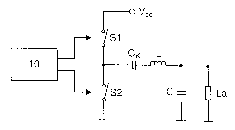
Figure 1 shows a ballast for operating a lamp ha. A
first and a second switch S1; S2 are arranged between
the supply voltage V~~ and ground. The center point
between the two switches Sl, S2, which are preferably
in the form of transistors, is connected via a coupling
capacitor CK to the output circuit, which comprises an
inductance L as well as a capacitor C. The switches S1;
S2 axe opened and closed by a drive circuit 10, which
is designed to drive the two switches S1; S2
alternately at at least two different frequencies. The
switching frequency between the two drive frequencies
is at least 60 Iiz, and preferably at least 80 Hz.
Figure 2 shows the time profile of the power Py
consumed in the lamp, which is correlated with the
brightness emerging from the lamp, plotted against the
frequency w. The frequency u~ is, for example, between
25 kHz and 125 kHa. A first frequency wa is correlated
with a first lamp power Pa, .a second frequency wb, which
is greater than w~, is correlated with a second lamp
power Pb which is less than the lamp power Pa. wa and wb
are two discrete successive drive frequencies, which
can be produced in the drive czreuit 10. Switching
backwards and forwards directly between the lamp power
Pa arid the lamp power Pb in the course of a control
process would lead zo sudden brightness changes, which
can be perceived by a human eye.
Figure 3 shows first of all the time profile during
operation of the ballast either at the lamp power P~ or
at the lamp power Pb, with the mains frequency of the

CA 02415509 2002-12-30
voltage mains system from which the ballast is driven
bezng reflected in the form of ripples in the time
profile of the mains frequency. According to the
invention, the ballast is operated at a lamp power Pa
during a time period td, and at the lamp power Pb during
a time period tb. The switching between the lamp power
Pa and the lamp power P~ is synchronized to the ripples,
although the switching need not necessarily take place
at the respective maxima. The resultant mean lamp power
Pm is accordingly
Pm ' Ita * Pa * tb * Pb) ~ ~te + tb)
The shaded areas in Figure 3 show the profile of the
lamp power with a ballast according to the invention.
When the ballast is operated with a DC voltage source,
no synchronization is required, of course. Tn this
case, the switching frequency between the lamp power Pa
and the lamp power P~ is chosen such that it is higher
than the flicker frequency which can be perceived by a
human eye.

Representative Drawing
A single figure which represents the drawing illustrating the invention.
Administrative Status

2024-08-01:As part of the Next Generation Patents (NGP) transition, the Canadian Patents Database (CPD) now contains a more detailed Event History, which replicates the Event Log of our new back-office solution.

Please note that "Inactive:" events refers to events no longer in use in our new back-office solution.

For a clearer understanding of the status of the application/patent presented on this page, the site Disclaimer , as well as the definitions for Patent , Event History , Maintenance Fee  and Payment History  should be consulted.

Event History

Description Date
Time Limit for Reversal Expired 2008-12-30
Application Not Reinstated by Deadline 2008-12-30
Inactive: Abandon-RFE+Late fee unpaid-Correspondence sent 2007-12-31
Deemed Abandoned - Failure to Respond to Maintenance Fee Notice 2007-12-31
Inactive: IPC from MCD 2006-03-12
Application Published (Open to Public Inspection) 2003-07-02
Inactive: Cover page published 2003-07-01
Inactive: IPC assigned 2003-03-07
Inactive: First IPC assigned 2003-03-07
Letter Sent 2003-02-17
Inactive: Filing certificate - No RFE (English) 2003-02-17
Inactive: Applicant deleted 2003-02-17
Application Received - Regular National 2003-02-12
Letter Sent 2003-02-12
Inactive: Filing certificate - No RFE (English) 2003-02-12

Abandonment History

Abandonment Date Reason Reinstatement Date
2007-12-31

Maintenance Fee

The last payment was received on 2006-11-09

Note : If the full payment has not been received on or before the date indicated, a further fee may be required which may be one of the following

  • the reinstatement fee;
  • the late payment fee; or
  • additional fee to reverse deemed expiry.

Patent fees are adjusted on the 1st of January every year. The amounts above are the current amounts if received by December 31 of the current year.
Please refer to the CIPO Patent Fees web page to see all current fee amounts.

Fee History

Fee Type Anniversary Year Due Date Paid Date
Application fee - standard 2002-12-30
Registration of a document 2002-12-30
MF (application, 2nd anniv.) - standard 02 2004-12-30 2004-12-01
MF (application, 3rd anniv.) - standard 03 2005-12-30 2005-12-01
MF (application, 4th anniv.) - standard 04 2007-01-01 2006-11-09
Owners on Record

Note: Records showing the ownership history in alphabetical order.

Current Owners on Record
PATENT-TREUHAND-GESELLSCHAFT FUER ELEKTRISCHE GLUEHLAMPEN MBH
Past Owners on Record
MARKUS HECKMANN
OLAF BUSSE
WOLFRAM SOWA
Past Owners that do not appear in the "Owners on Record" listing will appear in other documentation within the application.
Documents

To view selected files, please enter reCAPTCHA code :


To view images, click a link in the Document Description column. To download the documents, select one or more checkboxes in the first column and then click the "Download Selected in PDF format (Zip Archive)" or the "Download Selected as Single PDF" button.

List of published and non-published patent-specific documents on the CPD .

If you have any difficulty accessing content, you can call the Client Service Centre at 1-866-997-1936 or send them an e-mail at CIPO Client Service Centre.


Document
Description 
Date
(yyyy-mm-dd) 
Number of pages   Size of Image (KB) 
Description 2002-12-29 5 194
Abstract 2002-12-29 1 22
Claims 2002-12-29 2 52
Drawings 2002-12-29 1 16
Representative drawing 2003-03-11 1 3
Courtesy - Certificate of registration (related document(s)) 2003-02-16 1 107
Filing Certificate (English) 2003-02-16 1 160
Reminder of maintenance fee due 2004-08-30 1 110
Reminder - Request for Examination 2007-09-03 1 119
Courtesy - Abandonment Letter (Maintenance Fee) 2008-02-24 1 176
Courtesy - Abandonment Letter (Request for Examination) 2008-03-24 1 166