Sélection de la langue

Search

Sommaire du brevet 2415509 

Énoncé de désistement de responsabilité concernant l'information provenant de tiers

Une partie des informations de ce site Web a été fournie par des sources externes. Le gouvernement du Canada n'assume aucune responsabilité concernant la précision, l'actualité ou la fiabilité des informations fournies par les sources externes. Les utilisateurs qui désirent employer cette information devraient consulter directement la source des informations. Le contenu fourni par les sources externes n'est pas assujetti aux exigences sur les langues officielles, la protection des renseignements personnels et l'accessibilité.

Disponibilité de l'Abrégé et des Revendications

L'apparition de différences dans le texte et l'image des Revendications et de l'Abrégé dépend du moment auquel le document est publié. Les textes des Revendications et de l'Abrégé sont affichés :

  • lorsque la demande peut être examinée par le public;
  • lorsque le brevet est émis (délivrance).
(12) Demande de brevet: (11) CA 2415509
(54) Titre français: BALLAST POUR LAMPE ET METHODE D'UTILISATION D'UN BALLAST POUR LAMPE
(54) Titre anglais: BALLAST FOR A LAMP AND METHOD FOR OPERATING A BALLAST FOR A LAMP
Statut: Réputée abandonnée et au-delà du délai pour le rétablissement - en attente de la réponse à l’avis de communication rejetée
Données bibliographiques
(51) Classification internationale des brevets (CIB):
  • H05B 41/36 (2006.01)
  • H05B 41/38 (2006.01)
  • H05B 41/392 (2006.01)
(72) Inventeurs :
  • BUSSE, OLAF (Allemagne)
  • HECKMANN, MARKUS (Allemagne)
  • SOWA, WOLFRAM (Allemagne)
(73) Titulaires :
  • PATENT-TREUHAND-GESELLSCHAFT FUER ELEKTRISCHE GLUEHLAMPEN MBH
(71) Demandeurs :
  • PATENT-TREUHAND-GESELLSCHAFT FUER ELEKTRISCHE GLUEHLAMPEN MBH (Allemagne)
(74) Agent: SMART & BIGGAR LP
(74) Co-agent:
(45) Délivré:
(22) Date de dépôt: 2002-12-30
(41) Mise à la disponibilité du public: 2003-07-02
Licence disponible: S.O.
Cédé au domaine public: S.O.
(25) Langue des documents déposés: Anglais

Traité de coopération en matière de brevets (PCT): Non

(30) Données de priorité de la demande:
Numéro de la demande Pays / territoire Date
102 00 047.6 (Allemagne) 2002-01-02

Abrégés

Abrégé anglais


The invention relates to a ballast for a lamp having an
inverter which comprises at least one switch (S1; S2),
and having a drive circuit (10) for alternately opening
and closing the at least one switch (S1; S2) wherein
the drive circuit (10) is designed to drive the at
least one switch (S1; S2) alternately at at least two
different frequencies (.omega.a, .omega.b). It also relates to a
method for operating a ballast for a lamp having an
inverter which comprises at least one switch (S1; S2),
and having a drive circuit (10) for alternately opening
and closing the at least one switch (S1; S2) wherein
the drive circuit drives the at least one switch (S1;
S2) alternately at at lease two different frequencies
(.omega.a, .omega.b)

Revendications

Note : Les revendications sont présentées dans la langue officielle dans laquelle elles ont été soumises.


Claims
1. A ballast for a lamp having an inverter which
comprises at least one switch (S1; S2), and having
a drive circuit (10) for alternately opening and
closing the at least one switch (S1; S2)
characterized
in that the drive circuit (10) is designed to
drive the at least one switch (S1; S2) alternately
at at least two different frequencies (.omega.a, .omega.b).
2. The ballast as claimed in claim 1,
characterised
in that the drive circuit (10) is designed to
change between the different drive frequencies
(.omega.a, .omega.b) at a switching frequency which is chosen
such that the different brightnesses of the lamp
(La), which are correlated with the different
drive frequencies (.omega.a, .omega.b), can no longer be
resolved by a human eye.
3. The ballast as claimed in claim 2,
characterized
in that the switching frequency is at least 60 Hz,
in particular at least 80 Hz.
4. The ballast as claimed in one of the preceding
claims,
characterized
in that a mains rectifier is connected upstream of
the inverter arid can be fed from an AC voltage
network which is at a mains frequency, with the
switching frequency being synchronized to the
mains frequency.
5. The ballast as claimed in claim 4,
characterized

in that the mains frequency is 50 Hz and the
switching frequency is a multiple of 50 Hz, in
particular 100 Hz.
6. The ballast as claimed in claim 4,
characterized
in that the mains frequency is 60 Hz and the
switching frequency is a multiple of 60 Hz, in
particular 120 Hz.
7. The ballast as claimed in claim 4,
characterized
in that the mains frequency is a multiple of the
switching frequency.
8. A method for operating a ballast for a lamp having
an inverter which comprises at least one switch
(S1; S2), and having a drive circuit (10) for
alternately opening and closing the at least one
switch (S1; S2)
characterized
in that the drive circuit drives the at least one
switch (S1; S2) alternately at at least two
different frequencies (.omega.a, .omega.b).

Description

Note : Les descriptions sont présentées dans la langue officielle dans laquelle elles ont été soumises.

CA 02415509 2002-12-30
Patent-Treuhand-Gesellschaft fiiz
elektrische Gluhla~en mbH., Munich
Ballast foz a lamp and method for operating a ballast
for a lamp
Technical field
The present invention xelates to a ballast for a lamp
having an inverter which comprises at least one switch,
and having a drive circuit for alternately opening and
closing the at Least one switch, and to a method for
operating such a ballast.
prior art
In ballasts, which are controlled directly by a
microcontroller without any further signal conversion,
the possible operating frequencies cannot be chosen in
indefinitely fine steps. Due to the restrictions of fihe
hardware, in which particular mention should be made of
the register width and processor clock, only a specific
fixed number of possible operating frequencies can be
produced, When changing from one discrete frequency to
the next, for example as a result of control processes,
this results in abrupt brightness changes of the
connected lamp, which may be regarded as being
disturbing.
One possible way to counteract this is to increase the
clock frequency of the px-ocessor and to use broader
registers to refine the steps such that the remaining
sudden brightness changes are no longer conspicuous.
However, this is generally undesirable for cost
reasons. Typical solutions for this problem therefore
generally provide for the signal supply from the
microcontroller to b2 C.OnVezted from digital to
analogue form. In this case, the output signal from the

CA 02415509 2002-12-30
processor is normally integrated using a capacitor. The
resultant voltage then controls an oscillator, for
example a VCO (Voltage Controlled Oscillator). The
frequency of the VCO can be adjusted in very fine
steps. However, the costs incurred here ate also still
considerable.
Description of the aavention
The object of the present invention is therefore to
develop a ballast of the type mentioned initially, as
well as the method mentioned initially for operating a
ballast, such that abrupt brightness changes of a
connected lamp can be avoided in a cost-effective
manner.
This object is achieved by a ballast having the
features of patent claim 1, and by a method for
operating a ballast having the features of patent
claim 8.
The invention is based on the knowledge that the
integration of the changing light brightness is not
carried out using a capacitor provided for this
purpose, but by the inertia of human perception. A
periodically fluctuating lamp brightness is not
perceived if the fluctuation frequency is more than
80 Hz. Any perceivable brightness between the fixed
predetermined discrete values can be produced by
switching between at least t.wo different frequencies.
The drive circuit is preferably designed to carry out a
change between the different drive frequencies at a
switching frequency which is chosen such that the
different lamp brightnesses, which are correlated with
the different drive freqc.encies, can no longer be
resolved by a human eye. The switching frequency is
thus preferably at least 60 Hz, and in particular at
least 80 Hz.

CA 02415509 2002-12-30
A mains rectifier may be connected upstream of the
inverter, and may be fed from an AC voltage mains
system which is at a mains frequency, with the
switching frequency being synchronized to the mains
frequency. This is because. if ripple occurs at the
mains frequency or at multiples of it in the ballast,
low beat frequencies can occur if the drive is not
synchronized, whose frequency may be so low that these
freguencies can once again be perceived by the human
eye. By way of example, the mains frequency is 50 Hz or
60 Hz, and the corresponding switching frequencies are
then multiples of 50 Hz, in particular 100 Hz, or
multiples of 60 Hz, in particular 120 Hz.
Alternatively, it is also possible to provide for the
mains frequency to be a multiple of the switching
frequency.
When the ballast is operated from a DC voltage source,
for example from batteries, no synchronization is
required with externally produced frequencies. Tn this
case, a switching frequency is chosen which can be
implemented well technically and is at the same time
greater than the flicker frequency which can still be
perceived by the human eye.
Further advantageous developments of the invention are
defined in the dependent claims.
Description of the drawings
An exemplary embodiment will be described in more
detail in the following text, with reference to the
attached drawings, in which:,
Figure 1 shows a schematic illustration of one
exemplary embodiment of a ballast according
to the inventian~

CA 02415509 2002-12-30
Figure 2 shows a schematic illustration of the power
which is consumed in the lamp, as a function
of the frequency w; and
Figure 3 shows the time profile of the power which is
consumed in the lamp, for a ballast according
to the invention.
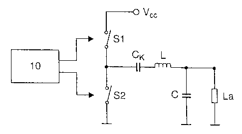
Figure 1 shows a ballast for operating a lamp ha. A
first and a second switch S1; S2 are arranged between
the supply voltage V~~ and ground. The center point
between the two switches Sl, S2, which are preferably
in the form of transistors, is connected via a coupling
capacitor CK to the output circuit, which comprises an
inductance L as well as a capacitor C. The switches S1;
S2 axe opened and closed by a drive circuit 10, which
is designed to drive the two switches S1; S2
alternately at at least two different frequencies. The
switching frequency between the two drive frequencies
is at least 60 Iiz, and preferably at least 80 Hz.
Figure 2 shows the time profile of the power Py
consumed in the lamp, which is correlated with the
brightness emerging from the lamp, plotted against the
frequency w. The frequency u~ is, for example, between
25 kHz and 125 kHa. A first frequency wa is correlated
with a first lamp power Pa, .a second frequency wb, which
is greater than w~, is correlated with a second lamp
power Pb which is less than the lamp power Pa. wa and wb
are two discrete successive drive frequencies, which
can be produced in the drive czreuit 10. Switching
backwards and forwards directly between the lamp power
Pa arid the lamp power Pb in the course of a control
process would lead zo sudden brightness changes, which
can be perceived by a human eye.
Figure 3 shows first of all the time profile during
operation of the ballast either at the lamp power P~ or
at the lamp power Pb, with the mains frequency of the

CA 02415509 2002-12-30
voltage mains system from which the ballast is driven
bezng reflected in the form of ripples in the time
profile of the mains frequency. According to the
invention, the ballast is operated at a lamp power Pa
during a time period td, and at the lamp power Pb during
a time period tb. The switching between the lamp power
Pa and the lamp power P~ is synchronized to the ripples,
although the switching need not necessarily take place
at the respective maxima. The resultant mean lamp power
Pm is accordingly
Pm ' Ita * Pa * tb * Pb) ~ ~te + tb)
The shaded areas in Figure 3 show the profile of the
lamp power with a ballast according to the invention.
When the ballast is operated with a DC voltage source,
no synchronization is required, of course. Tn this
case, the switching frequency between the lamp power Pa
and the lamp power P~ is chosen such that it is higher
than the flicker frequency which can be perceived by a
human eye.

Dessin représentatif
Une figure unique qui représente un dessin illustrant l'invention.
États administratifs

2024-08-01 : Dans le cadre de la transition vers les Brevets de nouvelle génération (BNG), la base de données sur les brevets canadiens (BDBC) contient désormais un Historique d'événement plus détaillé, qui reproduit le Journal des événements de notre nouvelle solution interne.

Veuillez noter que les événements débutant par « Inactive : » se réfèrent à des événements qui ne sont plus utilisés dans notre nouvelle solution interne.

Pour une meilleure compréhension de l'état de la demande ou brevet qui figure sur cette page, la rubrique Mise en garde , et les descriptions de Brevet , Historique d'événement , Taxes périodiques et Historique des paiements devraient être consultées.

Historique d'événement

Description Date
Le délai pour l'annulation est expiré 2008-12-30
Demande non rétablie avant l'échéance 2008-12-30
Inactive : Abandon.-RE+surtaxe impayées-Corr envoyée 2007-12-31
Réputée abandonnée - omission de répondre à un avis sur les taxes pour le maintien en état 2007-12-31
Inactive : CIB de MCD 2006-03-12
Demande publiée (accessible au public) 2003-07-02
Inactive : Page couverture publiée 2003-07-01
Inactive : CIB attribuée 2003-03-07
Inactive : CIB en 1re position 2003-03-07
Lettre envoyée 2003-02-17
Inactive : Certificat de dépôt - Sans RE (Anglais) 2003-02-17
Inactive : Demandeur supprimé 2003-02-17
Demande reçue - nationale ordinaire 2003-02-12
Lettre envoyée 2003-02-12
Inactive : Certificat de dépôt - Sans RE (Anglais) 2003-02-12

Historique d'abandonnement

Date d'abandonnement Raison Date de rétablissement
2007-12-31

Taxes périodiques

Le dernier paiement a été reçu le 2006-11-09

Avis : Si le paiement en totalité n'a pas été reçu au plus tard à la date indiquée, une taxe supplémentaire peut être imposée, soit une des taxes suivantes :

  • taxe de rétablissement ;
  • taxe pour paiement en souffrance ; ou
  • taxe additionnelle pour le renversement d'une péremption réputée.

Les taxes sur les brevets sont ajustées au 1er janvier de chaque année. Les montants ci-dessus sont les montants actuels s'ils sont reçus au plus tard le 31 décembre de l'année en cours.
Veuillez vous référer à la page web des taxes sur les brevets de l'OPIC pour voir tous les montants actuels des taxes.

Historique des taxes

Type de taxes Anniversaire Échéance Date payée
Taxe pour le dépôt - générale 2002-12-30
Enregistrement d'un document 2002-12-30
TM (demande, 2e anniv.) - générale 02 2004-12-30 2004-12-01
TM (demande, 3e anniv.) - générale 03 2005-12-30 2005-12-01
TM (demande, 4e anniv.) - générale 04 2007-01-01 2006-11-09
Titulaires au dossier

Les titulaires actuels et antérieures au dossier sont affichés en ordre alphabétique.

Titulaires actuels au dossier
PATENT-TREUHAND-GESELLSCHAFT FUER ELEKTRISCHE GLUEHLAMPEN MBH
Titulaires antérieures au dossier
MARKUS HECKMANN
OLAF BUSSE
WOLFRAM SOWA
Les propriétaires antérieurs qui ne figurent pas dans la liste des « Propriétaires au dossier » apparaîtront dans d'autres documents au dossier.
Documents

Pour visionner les fichiers sélectionnés, entrer le code reCAPTCHA :


Pour visualiser une image, cliquer sur un lien dans la colonne description du document. Pour télécharger l'image (les images), cliquer l'une ou plusieurs cases à cocher dans la première colonne et ensuite cliquer sur le bouton "Télécharger sélection en format PDF (archive Zip)" ou le bouton "Télécharger sélection (en un fichier PDF fusionné)".

Liste des documents de brevet publiés et non publiés sur la BDBC .

Si vous avez des difficultés à accéder au contenu, veuillez communiquer avec le Centre de services à la clientèle au 1-866-997-1936, ou envoyer un courriel au Centre de service à la clientèle de l'OPIC.


Description du
Document 
Date
(aaaa-mm-jj) 
Nombre de pages   Taille de l'image (Ko) 
Description 2002-12-29 5 194
Abrégé 2002-12-29 1 22
Revendications 2002-12-29 2 52
Dessins 2002-12-29 1 16
Dessin représentatif 2003-03-11 1 3
Courtoisie - Certificat d'enregistrement (document(s) connexe(s)) 2003-02-16 1 107
Certificat de dépôt (anglais) 2003-02-16 1 160
Rappel de taxe de maintien due 2004-08-30 1 110
Rappel - requête d'examen 2007-09-03 1 119
Courtoisie - Lettre d'abandon (taxe de maintien en état) 2008-02-24 1 176
Courtoisie - Lettre d'abandon (requête d'examen) 2008-03-24 1 166