Language selection

Search

Patent 2415517 Summary

Third-party information liability

Some of the information on this Web page has been provided by external sources. The Government of Canada is not responsible for the accuracy, reliability or currency of the information supplied by external sources. Users wishing to rely upon this information should consult directly with the source of the information. Content provided by external sources is not subject to official languages, privacy and accessibility requirements.

Claims and Abstract availability

Any discrepancies in the text and image of the Claims and Abstract are due to differing posting times. Text of the Claims and Abstract are posted:

  • At the time the application is open to public inspection;
  • At the time of issue of the patent (grant).
(12) Patent: (11) CA 2415517
(54) English Title: CHILL TUBE
(54) French Title: TUBE REFROIDISSEUR
Status: Granted
Bibliographic Data
(51) International Patent Classification (IPC):
  • B22D 11/22 (2006.01)
  • B22D 11/04 (2006.01)
  • F28F 1/00 (2006.01)
(72) Inventors :
  • HAURI, ROLAND (Switzerland)
  • EICHHOLZ-BOLDT, RAIMUND (Germany)
  • KOLBECK, DIETMAR (Germany)
  • HUGENSCHUTT, GERHARD (Germany)
(73) Owners :
  • KME GERMANY GMBH & CO. KG (Germany)
(71) Applicants :
  • KM EUROPA METAL AG (Germany)
(74) Agent:
(74) Associate agent:
(45) Issued: 2010-02-23
(22) Filed Date: 2003-01-03
(41) Open to Public Inspection: 2003-07-31
Examination requested: 2007-10-25
Availability of licence: N/A
(25) Language of filing: English

Patent Cooperation Treaty (PCT): No

(30) Application Priority Data:
Application No. Country/Territory Date
102 03 967.4 Germany 2002-01-31

Abstracts

English Abstract

A chill tube having a double T-shaped inner and outer cross-section in beam blank format is encased in a water-guiding jacket adapted to its outer contour while forming a water gap. The wall thickness of the chill tube in the rounded transition regions from middle crosspieces, which face each other head to head and are drawn in towards the longitudinal axis, to the neighboring crosswise positioned flanges is dimensioned at least partially smaller than in the remaining wall sections. The reduction in wall thickness is implemented by longitudinal hollow recesses. These recesses extend only in the height range of the bath level. Into the cross-sectional regions which are formed by the outer contour of chill tube as well as the inner contour of the water-guiding jacket, filler pieces are incorporated, which are adapted to this cross-section.


French Abstract

Un tube refroidisseur doté d'une double section transversale interne et externe en T dans un format de découpé de poutre est placé dans une enveloppe de guidage d'eau adapté à son contour externe, tout en formant un écran d'eau. L'épaisseur de la paroi du tube refroidisseur dans les zones de transition arrondies des pièces transversales intermédiaires, disposées en vis-à-vis et inclinées selon l'axe longitudinal, par rapport aux rebords avoisinants positionnés de façon transversale est au moins partiellement inférieure à celle des autres sections de la paroi. La réduction de l'épaisseur de la paroi est assurée par des fraisures creuses longitudinales. Ces fraisures s'étendent seulement sur le plan de la hauteur du niveau de bain. Dans les zones en section transversale qui sont formées par le contour externe du tube refroidisseur ainsi que le contour interne de l'enveloppe de guidage d'eau, on place des pièces de remplissage qui sont adaptées à cette section transversale.

Claims

Note: Claims are shown in the official language in which they were submitted.


1. A chill tube having a double T-shaped inner and outer cross-section
in beam blank format, the chill tube being encased in a water-guiding jacket
adapted to its outer contour while forming a water gap, wherein the wall
thickness of the chill tube in rounded transition regions from middle
crosspieces, which face each other head to head and are drawn in towards a
longitudinal axis, to neighboring crosswise positioned flanges is dimensioned
at least partially smaller than in the remaining wall sections.

2. A chill tube according to claim 1, wherein the wall thickness in the
transition regions is reduced only in the height range of the bath level.

3. A chill tube according to claim 1 or 2, wherein longitudinal hollow
recesses are provided on the outer side of the transition regions.

4. A chill tube according to any one of claims 1 to 3, wherein on the
outer side of the transition regions, a plurality of longitudinal grooves are
provided which run next to one another.

5. A chill tube according to any one of claims 1 to 3, wherein in the wall
sections of the transition regions, a plurality of longitudinal bores are
provided
which run next to one another.

6. A chill tube according to any one of claims 1 to 5, wherein the water-
guiding jacket has an essentially rectangular cross-section, and,

6


between the water-guiding jacket as well as the crosspieces and the flanges,
filler pieces adapted to the cross-sectional region by the outer contour of
the
chill tube as well as the inner contour of the water-guiding jacket are

incorporated.

7

Description

Note: Descriptions are shown in the official language in which they were submitted.


CA 02415517 2003-01-03

C3II I. 'I`i.113E
BAC~CrROUND C3F 3HE INVENTIQN
Field of the Inventon.
The invention relates to a mold/chill tube having a double T-shaped inner and
outer cross section in beam blank format which is encased in a water-guiding
jacket adapted to its outer contour while forming a water gap,

Descri tion of Re atec~Art
In the continuous casting of metals using a chill tube, the material
temperatures in the chill wall result from the heat stresses occurring during
continuous casting and the cooling conditions by the respective medium, which
normally, in the form of water, flows from bottom to top in a water gap
between
a water-guiding jacket fitted to the outer -contour of the chill tube and the
outer
surface of the chill tube, thereby taking -up the heat encountered and
carrying it
off. The removal of the heat with the aid of the cooling water is largely
determined by the speed of the water'-in the water gap.

In the continuous casting of metals using a chill tube of the type in question
here, it has been observed that, because of the special geometry of the beam
blank format, extremelocal heat stresses occur in the transition regions from
middle crosspieces, which face one another head to head and are drawn in in
the direction towards the longitudinal .axis, and the bordering flanges which
are
positioned at an angle. In the case of unfavorable geometrxcal, relationships
of
the transition regions, these local heat stresses lead to overheating of the
chill
tube, and, as a result, to a drastic reduction in its service life.

SU1VINtARY Op TFILINVFN'1^ION
It is an object of the invention to deverop a mold/ chill tube hwring a double
T-shaped inner and outer cross section ira, beam blank format for the


CA 02415517 2003-07-11

continuous casting of metals, iri which local overheating of the transitional
regions is avoided, and thereby a longer service life is achieved.

Accordingly, the invention provides a chill tube having a double T-shaped
inner
and outer cross-section in beam blank format, which is encased in a water-
guiding jacket adapted to its outer contour while forming a water gap,
lwherein
the wall thickness of the chill tube in the rounded transition regions from
middle crosspieces, which face each other head to head and are drawn in
towards a longitudinal axis, to the neighboring crosswise positioned flanges
is

dimensioned at least partially smaller than in the remaining wall sections.
BRIEF DESCRIPTION OF THE DRAWINGS

Embodiments of the inventiori will be described in greater detail with
reference
to the following drawings, wherein:

Figure 1 shows in schematic perspective, a chill tube in beam blank format
without a water-guiding jacket having lateral filler pieces;

Figure 2 shows likewise in schematic perspective, the chill tube of Figure 1
along with a separately shown filler piece;

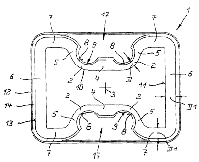
Figure 3 shows a top view of a chill tube without cover plate in the region of
the
lateral channels, but having a water-guiding jacket; and

Figure 4 shows a top view onto a chill tube according to further specific
embodiments without cover plate and water-guiding jacket.

DETAILED DESCRIPTION OF THE INVENTION

On account of the at least partial reduction of the wall thickness of the
chill
tube in the rounded transition regions, a clearly improved heat removal is
achieved, so that a local overheating of the transition regions is avoided,
and as

2


CA 02415517 2003-01-03

a result, the service life of the chill tube is clearly increased.

With respect to the fact that, in the continuous casting of rnetals, the
highest
heat stress in the chill tube occurs, as a rule, at the height range of the
bath
level, it is provided that the wall thickness in the transition regions is
reduced
only at the height range of the bath level.

The reduction of the wall thickness of the chill tube in the rounded
transition
regions can be carried out in various ways.

.0
One option is that at the outside of the transition regions longitudinal
hollow
recesses are provided. The curvature of the recesses, in this case, may be
largely adapted to the curvature of the inner surface of the transition
regions.
In addition, the reduction in wall thickness, in the form of a hollow recess,
has
the advantage that the outer surface of the chill tube is enlarged, so that an
even better cooling effect may be achieved.

Another possibility of wall thickness reduction is that on the outside of the
transition regions, a plurality of longitudinal grooves running side by side
are
provided. The cross section and/or depth of the grooves may be dimensioned to
be equal or different in each transition region. The cross section of the
grooves
may be rounded or angular, such as triangular.

Furthermore, for the reduction in wall thickness in the wall sections of the
transition regions, it is also possible to provide a plurality of longitudinal
bores
running next to one another. The size of the bores, their number, their
distance
apart, and also their position in relation to the outside or the inside
contour of
the chill tube may vazy, However, it is advantageous if the bores are closer
to
the -outex surface than to the inner surface of the chill tube.
3

Since heat removal. using cooling water is determined, as is known, by the
speed
of the water in the water gap between the chill tube and the water-guiding

3


CA 02415517 2003-01-03

jacket, this water gap should be maintained even in the region of the wall
thickness reduction, in order to guarantee uniform water speed in the entire
water gap. This being the case, in a specific embodiment, it is provided that
the
water-guiding jacket has a rectangular cross section, and, between the
water-guidirig jacket as well, as the crosspieces and the flanges, filler
pieces
adjusted to the cross sectional region by the outer contour of the chill tube
as
well as the inner contour of the water-guiding jacket are incorporated.

The numeral 1 in Figures 1 through 4 denotes a chill tube having a double
L0 T-shaped inner and outer cross section in beam blank format. Chill tube 3.
is
used for the continuous casting of inetals. In Figures 3 and 4, the curvature
of
chill tube 1 in the longitudinal direction is not shown.

As may be seen in greater detail in Figure 3, wall thickness D of chill tube 1
in
rounded transition regions 2 from middle crosspieces 4, which face each other
head to head and are drawn in towards longitudinal axis 3, to the neighboring,
crosswise positioned flanges 5 is dimensioned less than wall thickness I.71 in
t-he
remainder of wall sections b and 7.

The reduction in wall thickness takes place in the specific embodiment of
Figures 1 through 3 in that, on the outside of transition regions 2,
loxigitudina.l
hollow recesses 8 are provided, These recesses 8 extend, as may be seen in
Figure 2, only as far as the height range of the bath level which is not shown
in
detail. Curvature 9 of recesses 8 is largely adjusted to curvature 10 of inner
surface 11 of chill tube I. in transition ranges 2.

On the peripheral side of chill tube 1 there is a water-guiding jacket 12
which
may be seen only in Figure 3, having an.essentially rectan.gutar cross
section.
Between water-guiding jacket 12 and outer surface 13 of chill tube 1, a water
gap 14 is formed through which cooling water is guided from bottom to top at a
predefined water speed.

4


CA 02415517 2003-01-03

In order to achieve uniform water speed in water gap 14, even in lateral
channels 15 of chill tube 1, which, according to Figures 1 and 2 are closed
off at
their upper end by cover plate 16 in water gap 14, these channels are provided
with filler pieces 17, which, in the upper region are also adapted to'hollow
recesses 8.

Figure 4 shows four different specific embodiments of how the reduction in
wall
thickness of chill tube I may also be implemented.

In transition regions 2a, 2b, 2c; on the outer side, several longitudinal
grooves
18, 18a, 18b are provided which run next to one another, Whereas in transition
region 2a grooves 18 have a triangular cross section, grooves 18a, 18b in
transition regions 2b, 2c have rounded bottoms. In this context, grooves 18b
in
transition region 2c have a greater depth.than grooves 18a in transition
region
2b.

In transition region 2d, reduction in wall thickness is implemented by bores
19.
These bores 19 lie closer to outer surface 13 of chill tube 1 than to inner
surface
11,

Both grooves 18, 18a, .1 8and bores 19 extend, as do recesses 8, only in the
height range of the bat% level.

5

Representative Drawing
A single figure which represents the drawing illustrating the invention.
Administrative Status

For a clearer understanding of the status of the application/patent presented on this page, the site Disclaimer , as well as the definitions for Patent , Administrative Status , Maintenance Fee  and Payment History  should be consulted.

Administrative Status

Title Date
Forecasted Issue Date 2010-02-23
(22) Filed 2003-01-03
(41) Open to Public Inspection 2003-07-31
Examination Requested 2007-10-25
(45) Issued 2010-02-23

Abandonment History

There is no abandonment history.

Maintenance Fee

Last Payment of $450.00 was received on 2020-12-21


 Upcoming maintenance fee amounts

Description Date Amount
Next Payment if small entity fee 2022-01-04 $253.00
Next Payment if standard fee 2022-01-04 $624.00

Note : If the full payment has not been received on or before the date indicated, a further fee may be required which may be one of the following

  • the reinstatement fee;
  • the late payment fee; or
  • additional fee to reverse deemed expiry.

Patent fees are adjusted on the 1st of January every year. The amounts above are the current amounts if received by December 31 of the current year.
Please refer to the CIPO Patent Fees web page to see all current fee amounts.

Payment History

Fee Type Anniversary Year Due Date Amount Paid Paid Date
Application Fee $300.00 2003-01-03
Registration of a document - section 124 $100.00 2003-03-26
Maintenance Fee - Application - New Act 2 2005-01-04 $100.00 2004-12-15
Maintenance Fee - Application - New Act 3 2006-01-03 $100.00 2005-12-28
Maintenance Fee - Application - New Act 4 2007-01-03 $100.00 2006-12-29
Request for Examination $800.00 2007-10-25
Maintenance Fee - Application - New Act 5 2008-01-03 $200.00 2007-12-21
Maintenance Fee - Application - New Act 6 2009-01-05 $200.00 2008-12-30
Final Fee $300.00 2009-10-14
Maintenance Fee - Application - New Act 7 2010-01-04 $200.00 2009-12-16
Maintenance Fee - Patent - New Act 8 2011-01-04 $400.00 2011-01-13
Maintenance Fee - Patent - New Act 9 2012-01-03 $200.00 2011-12-23
Maintenance Fee - Patent - New Act 10 2013-01-03 $250.00 2012-12-20
Maintenance Fee - Patent - New Act 11 2014-01-03 $250.00 2013-12-30
Maintenance Fee - Patent - New Act 12 2015-01-05 $250.00 2014-12-23
Registration of a document - section 124 $100.00 2015-08-31
Maintenance Fee - Patent - New Act 13 2016-01-04 $250.00 2015-12-22
Maintenance Fee - Patent - New Act 14 2017-01-03 $250.00 2016-12-23
Maintenance Fee - Patent - New Act 15 2018-01-03 $450.00 2017-12-22
Maintenance Fee - Patent - New Act 16 2019-01-03 $450.00 2018-12-21
Maintenance Fee - Patent - New Act 17 2020-01-03 $450.00 2019-12-20
Maintenance Fee - Patent - New Act 18 2021-01-04 $450.00 2020-12-21
Owners on Record

Note: Records showing the ownership history in alphabetical order.

Current Owners on Record
KME GERMANY GMBH & CO. KG
Past Owners on Record
EICHHOLZ-BOLDT, RAIMUND
HAURI, ROLAND
HUGENSCHUTT, GERHARD
KM EUROPA METAL AG
KME GERMANY AG
KME GERMANY AG & CO. KG
KOLBECK, DIETMAR
Past Owners that do not appear in the "Owners on Record" listing will appear in other documentation within the application.
Documents

To view selected files, please enter reCAPTCHA code :


To view images, click a link in the Document Description column. To download the documents, select one or more checkboxes in the first column and then click the "Download Selected in PDF format (Zip Archive)" or the "Download Selected as Single PDF" button.

List of published and non-published patent-specific documents on the CPD .

If you have any difficulty accessing content, you can call the Client Service Centre at 1-866-997-1936 or send them an e-mail at CIPO Client Service Centre.


Document
Description 
Date
(yyyy-mm-dd) 
Number of pages   Size of Image (KB) 
Abstract 2003-01-03 1 31
Description 2003-01-03 5 282
Claims 2003-01-03 3 165
Drawings 2003-01-03 2 49
Representative Drawing 2003-03-17 1 15
Cover Page 2003-07-14 1 47
Abstract 2003-07-11 1 26
Description 2003-07-11 5 273
Claims 2003-07-11 2 48
Representative Drawing 2010-01-27 1 17
Cover Page 2010-01-27 1 47
Correspondence 2003-02-13 1 23
Assignment 2003-01-03 3 109
Fees 2005-12-28 1 35
Assignment 2003-03-26 7 189
Prosecution-Amendment 2003-07-11 6 194
Fees 2004-12-15 1 36
Fees 2006-12-29 1 35
Prosecution-Amendment 2007-10-25 1 33
Fees 2007-12-21 1 38
Prosecution-Amendment 2008-05-20 1 33
Fees 2008-12-30 1 37
Correspondence 2009-10-14 1 25
Fees 2011-01-13 1 201
Assignment 2015-08-31 26 1,069