Note: Descriptions are shown in the official language in which they were submitted.
CA 02415546 2005-07-18
1
Device for Mechanically and Electrically Checking the Switching
Device of a Railway Switch Machine
The invention relates to a device for checking the operation of
devices used to displace movable switch parts, in which the
movable switch parts are connected with each other by a coupling
rod.
A device for operating movable switch parts is known, for instance,
from Australian Patent Publication No. 405,925 published May 15,
1999 (hereinafter "AT 405 925 B"). In that known device, two
relatively axially movable parts are displaceable into a position
mutually coupled in a positive and force-transmitting manner in at
least one direction of movement, wherein the relatively displaceable
parts are comprised of a tube and a rod guided within the tube and
are at least partially arranged in a stationary external tube. The
locking members used to lock the end positions are formed by balls
cooperating with the relatively axially displaceable parts and the
external tube, and are displaceable in the radial direction into a
locking position in a recess or internal annular groove of the
external tube. The rod guided within the tube, at the same time, is
designed as a piston rod for a hydraulic cylinder piston unit such
that the device known from AT 405 925 B not only ensures the locking
of end positions of movable switch parts, but, at the same time,
also causes the adjustment of said switch parts. In that known
device a rigid coupling rod is additionally provided, via which the
switch tongues are connected in a manner that, upon displacement of
a tongue, the respectively corresponding movement of the second
tongue will be safeguarded in a positive and force-transmitting
manner.
Numerous proposals have already become known for checking the
correct mode of functioning of such end position locking and
adjusting devices. AT 405 925 B, for instance, describes sensors
which are arranged adjacent the end side of the hydraulic cylinder
piston unit or cylinder, thus signaling the distance of the tubular
structural component connected with the tongue from the required
end position. A fracture of the coupling rod, for instance,
entails the risk of the synchronous movement of the two tongues
being no longer safeguarded such that the tongue moving from
the closed into the open position will be secured against
further displacement, be a separate locking groove, in a
position
CA 02415546 2005-07-18
- 2 -
in which the correct end position has not been reached. In that
case the sensors will indicate too large a distance of the tongue
from the required end position, yet such an operation control
entails the drawback that it cannot be taken for sure whether the
coupling rod has actually broken or whether a sensor does not
function correctly. Another safety device for the monitoring of
the switchover movement of moveable switch parts is known from PCT
International Patent Application No. PCT/AT97/00051 published on
Sept. 18, 1997 as WO 97/33784, in which the distance between the
stock rail and the closed tongue is detected by inductive sensors in
order to check the precise abutment of the tongue.
Bearing in mind the constantly increasing demand made on the
control of railway switches and considering the safety rules
provided by the railway operators, which become stricter and
stricter, the hitherto known safety devices are insufficient, and
it is therefore an object of the present invention to provide a
device which enables an additional operation checkout of devices
used to displace, and lock the end positions of, movable switch
parts. The invention, in particular, aims to provide an additional
mechanical operation checkout by which any deviation of the tongue
position from the respective set position and any operation
failure in end position locking can be directly monitored
electronically, and the exact cause of trouble can be immediately
concluded from the generated signals. To solve this object, the
configuration according to the invention essentially consists in
that the coupling rod is comprised of two coupling rod parts that
are relatively movable in the axial direction, and that sensors
are provided for the detection of at least two different
displacement positions of the coupling rod parts. Due to the fact
that a two-part coupling rod is provided, the two parts of which
are relatively movable in the axial direction, the axial length of
the coupling rod is changed during the switching procedure of the
switch, and it becomes thus feasible to generate during the
switching procedure sensor signals which indicate the different
displacement positions of the coupling rod parts relative to each
other. Consequently, sensors are provided for the detection of at
least two different displacement positions of the coupling rod
parts. Such a two-part coupling rod is particularly suitable when
using switching devices in which the movable switch parts are
moved not synchronously, i.e., for instance, via a rigid coupling
rod, but in which the open tongue is unlocked first and displaced
- 3 -
over a first partial course, whereupon the switching procedure of
the closed tongue is only initiated. Such a switching device
offers the advantage that the respective tongue being in the
closed position is kept in that position for an extended period of
time, namely even during the beginning of the switching procedure.
During the whole switching procedure, the coupling rod parts are,
thus, moved in a manner that the coupling rod will at first become
longer at the beginning of the switching procedure, will then keep
its length and will again reach its original length at the end of
the switching procedure. The sensors can thus signal at least
three shifting operations during the whole switching procedure so
as to ensure a nearly continuous operation checkout of the
switching device. In cooperation with further control means, for
instance means integrated in the locking device or means directly
attached to the rails, a second control level can be realized with
the checkout device according to the invention, thus also enabling
the assessment of the cause of a possible failure.
A preferred further development of the device according to the
invention consists in that the coupling rod parts comprise stops
for the delimitation of their relative axial movability. It is
thereby ensured that a change in the length of the coupling rod is
feasible only within defined limits and that the coupling rod,
after having reached the maximum length provided by the stops,
will consequently assume the function of a rigid coupling rod,
thus providing a synchronous movement of the two movable switch
parts over a portion of the displacement path. This has the
advantage that the locking of one tongue simultaneously ensures
the securement of the second tongue to some extent, even if the
locking device for one of the two tongues does no longer function
correctly.
In a particularly advantageous .manner, one coupling rod part
comprises a tubular part encompassing at least one axial partial
region of the other coupling rod part. Such a configuration
enables the coaxial arrangement of said one rod part within the
tubular part of the other coupling rod part in a manner that, in
the main, an encapsulated, outwardly closed device is produced,
within which also the sensors and other components can be arranged
so as to be protected from external influences.
CA 02415546 2003-O1-09
- 4 -
In a particularly simple manner, the tubular part of one coupling
rod part comprises a stop engaging a piston-shaped end piece of
the other coupling rod part from behind. Thus, an exact stop is
defined in a simple manner, which defines the maximum length of
the coupling rod.
In an advantageous manner, the coupling rod parts are
interconnected via a spring and, in particular, a helical spring.
Such a configuration offers the advantage that the mutual
displacement of the two coupling rod parts relative to each other
will not be impeded, but that the coupling rod will be retained in
its starting position in the event of a possible fracture of the
coupling rod, i.e., if the two tongues are no longer rigidly
connected with each other. The spring keeps the two coupling rod
parts in a defined position relative to each other, in which the
two coupling rod parts cannot be relatively displaced due to the
action of the spring such that the sensors will not be able to
generate switching signals. In this manner, a fracture of the
coupling rod will be safely recognized even in a monitoring
station locally remote from the switching device.
In a particularly simple manner, the sensors are designed as
contact switches such that the reliability of such sensors can be
further increased and an appropriate signal will be reliably
generated only if the respective end position has been reached. In
a preferred manner, a first sensor is rigidly connected with a
coupling rod part, which sensor cooperates with an actuation
member arranged on the tubular part in order to detect a first
displacement end position of the coupling rod parts. This sensor
is thus arranged in a manner so as to be displaceable together
with one coupling rod part relative to the other coupling rod part
and, after having reached a displacement end position, i.e.,
during the cooperation of the stops for delimiting the change in
length of the coupling rod, cooperate with a rigid actuation
member arranged on the tubular part, thus generating a signal. It
is, furthermore, preferred that a second sensor is rigidly
connected with a coupling rod part, which second sensor cooperates
with a stop surface provided within the tubular part, in order to
detect a second displacement end position of the coupling rod
parts, wherein the stop surface, furthermore, may be mounted
within the tubular part so as to be resiliently displaceable
CA 02415546 2003-O1-09
- 5 -
relative to the same. Such a resilient mounting of the stop
surface 'for the second sensor, which signals the displacement end
position that corresponds to the abutment of the tongues, has the
advantage that an elastic spring deflection of the closed tongue,
which can, for instance, be caused by an overrunning train, will
not trigger a switching signal, since the resiliently mounted stop
surface follows this resilient movement of the tongue.
In a particularly advantageous manner, the configuration is
devised such that the stops are arranged in a displaceable manner.
This enables the delimitation of the change in length of the
piston rod defined by the stops to be adjusted in a manner that
the-checking device can be adapted to the respective conditions
provided by the switching and locking device. To this end, the
piston-shaped end piece advantageously is connected with a
coupling rod part via a thread, wherein also the tubular part may
be connected with a coupling rod part via a thread.
In order to enable the central monitoring of the switch lock as
well as the correct operation of the railway switch, the sensors
are advantageously connected with an evaluation and monitoring
device. To such an evaluation and monitoring device also the
signals of other sensors can be fed so as to enable a detailed
failure analysis.
In the following, the invention will be explained in more detail
by way of exemplary embodiments schematically illustrated in the
drawing. Therein, Fig. 1 illustrates a switch operating device
including a coupling rod; Fig. 2 is an enlarged illustration of
the left side of the switching device according to Fig. 1; Fig. 3
is an enlarged illustration of the right side of the switching
device according to Fig. 1; and Fig. 4 is a partial illustration
of the coupling rod in section.
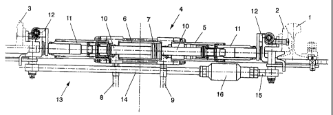
Fig. 1 depicts a stock rail 1 and a switch tongue bearing against
the stock rail 1, which is denoted by 2. The open switch tongue is
denoted by 3. Between the switch tongues 2 and 3 is provided a
device for displacing and locking the positions of the switch
tongues 2 and 3, which is denoted by 4. The switching device 4
comprises an externally arranged tube 5 which extends on both
sides of a central portion and 'is designed as a cyli nder 6 . A
CA 02415546 2003-O1-09
CA 02415546 2005-07-18
- 6 -
hydraulically movable piston 7 is provided in the interior of the
cylinder 6, hydraulic medium being pressed into the respectively
active working volumes via hydraulic ducts 8 and 9. The piston 7
is connected with a continuous piston rod 10 having different
cross-sectional portions over its axial length. Furthermore, tubes
11 are provided, which are connected with the switch tongues 2 and
3, respectively, via connection means 12. The connection means 12,
which are described in detail in PCT International Patent
Application No. PCT/AT98/00241 published on April 29, 1999 as WO
99/20511, ensure that vibrations of the switch tongues 2 and 3
will be completely kept away from the switching and locking
system 4 while simultaneously enable the play-free absorption of
the switching forces. Fig. l, furthermore, depicts a coupling
rod 13 which is comprised of rod parts 14 and 15. Parts 14 and
15 are each coupled to a part of the connection means 12, which
part is connected with the switch tongue 2 and 3, respectively.
The encapsulated portion 16 of fhe coupling rod 13 is
illustrated in more detail in Fig.4 and further described below.
From Figs. 2 and 3, the mode of operation of the switching and
locking mechanism is more clearly apparent. The left side of Fig.
1, which is illustrated in Fig. 2, constitutes that side which is
responsible for the locking position of the open tongue 3. The
locking elements, which are comprised of an expandable ring 17 and
the associated balls 18, are kept in the locked position in a
recess 21 of the external tube 5 by an axial portion 19 of the
piston rod l0 against a stop 20, the stop 20 and the ring 17 thus
preventing the tube 11 connected with the tongue 3 from being
displaced from the open position of the tongue into a closed
position. This locked position for the open tongue 3 can be undone
only by displacing the piston rod 10 in the sense of arrow 22 by
the aid of the piston 7, thus causing the balls 18 to reach the
reduced-diameter axial portion 23 of the piston rod 10. Upon
further movement of the piston rod 10 in the sense of arrow 22, a
stop shoulder 24 of the larger-diameter portion 19 of the piston
rod 10 enters into an active connection with the balls 25 so as to
effect an actuation of the switch tongue 3 via the tube 11. At the
same time, however, the displacement of the piston rod ir_ the
sense of arrow 22 causes the closed tongue 2 to be unlocked, as is
illustrated in Fig. 3. The piston rod 10 reaches a position in
which the externally located ring 26, which is in the locked
position, is able to emerge from its locked position onto the
- 7 -
reduced-diameter end portion 28 of the coupling rod 10 under the
action of a spring 27 and its associated balls 25, thus enabling a
relative displacement of the tubular part 11 relative to the
external tube 5. Upon further displacement of the piston rod 10 by
feeding fluid to the piston 7 in the sense of arrow 22, the
internally arranged stop shoulder .29 of the axial portion 19
designed with a full cross section will, as a rule, not enter into
an active connection with the balls 18, since the entrainment of
the tongue 2 is effected via the coupling rod 13.
The overlapping lengths of the locking members may, for instance,
be chosen such that the active displacement of the open tongue 3
will start after a piston displacement of 14 mm (a) so as to
effect the entrairsnent of the coupling rod part 14 by the open
tongue 3. As is more clearly apparent from Fig. 4, the coupling
rod part 14 at the beginning of the switching procedure, thus,
moves in the sense of arrow 22, whereby the coupling rod part 15,
which is connected with the closed tongue 2, remains yet
immovable. The coupling rod part 15 is herein connected via a
thread with a tubular part 30 encompassing the coupling rod part
14. Connected with the coupling rod part 14 is a piston-shaped end
piece 31 which is engaged from behind by a stop 32 of the tubular
part 30. Between the stop 33 of the piston-shaped end piece 31 and
the stop 32 of the tubular part 30, a distance b_ is provided at
the beginning of the switching procedure. After a piston stroke
of, for instance, 12 mm, the piston-shaped end piece 31 comes into
abutment on the stop 32 of the tubular part 30 such that the
coupling rod part 15 and hence the closed tongue 2 will be
entrained. At this point of time, also the lock of the closed
tongue 2 has already been undone such that the tongue 2 is
displaced via the coupling rod from the closed~into the open
position. As long as the entrainment of the closed tongue 2 is
effected directly by the coupling rod, no active entrainment of
the closed tongue 2 will be effected by the piston rod 10, since
the balls 18 will not bear against the stop 29 of the piston rod.
To this end, the length c must be chosen to be larger than the sum
of lengths _a and b_.
Only as the switch tongue 3 enters into abutment on the stock rail
is the entrainment of the switch tongue 2 via the coupling rod
stopped such that the balls 18 will bear against the stop 29 and
CA 02415546 2003-O1-09
g
hence cause the active entrainment of the tongue 2 by the piston
rod 10. From this point of time, the stop 33 of the piston-shaped
end piece 31 moves again away from the stop 32 of the tubular part
30 until the switch tongue 2 is locked via the ring 17 and the
locking balls 18. The original distance b will then be again
present between the stop 33 and the stop 32 of the piston rod
parts.
To the coupling rod part 14 sensors 34 and 35 are rigidly
connected, which signal the respective displacement end positions
of the coupling rod parts 14 and 15. In the initial position, in
which the stops 32 and 33 are kept at a distance b from each
other, the contact switch 35 bears against the annular contact
part 36. During the switching procedure, the sensor 34 will then
contact a counter contact 37 attached to the tubular part 30,
whereupon the contact switch 35 triggers a switching signal at the
end of the adjustment procedure. During the whole, switching
procedure, a sequence of switching signals is thus generated,
which enables an accurate operation checkout of the switching
device.
Between the end face 38 and the end face 39, an axial play _d will
remain, which can be overcome by the elastic spring deflection or
by vibrations of the closed tongue. If the maximum play
permissible of the tongue adjusts, this will cause the tubular
part 30 to immediately abut on the coupling rod part 14 so as to.
ensure further locking of the open tongue via the coupling rod. In
order not to trigger any switching signals of the sensors 35
during such vibrations or spring deflections of the closed tongue,
the annular contact part 36 is resiliently mounted within the
tubular part 30 via a spring 40.
A spring 41 is provided between the coupling rod part 15 and the
end piece 31 of the other coupling rod part 14. At a break of the
coupling rod, the spring 41 causes the distance b between the
stops 32 and 33 to be maintained. In this manner, a relative
displacement of the coupling rod parts 14 and 15 relative to each
other can be avoided so that no signals will be triggered by the
contact switches 34 and 25 in that case: On the whole, the two
coupling rod parts 14 and 15 are secured via a nut 42.
CA 02415546 2003-O1-09