Note: Descriptions are shown in the official language in which they were submitted.
CA 02415948 2003-01-17
WO 02/06156 PCT/US01/40614
METHOD OF MAKING ALUMINIUM OXYNITRIDE AND ALUMINIUM OXYNITRIDE PREPARED BY THE
METHOD
BACKGROUND
This invention relates to ceramic compounds and more particularly to aluminum
oxynitride.
As is known in the art, aluminum oxynitride having the chemical composition
A123-
1/3X027+XN5-X, 0.429 < x< 2 (AION) is a ceramic material that has a wide range
of uses
I
because of its relatively high degree of transparency over the optical
wavelength range of
about 0.2 microns up to about 5 microns. Accordingly, A1ON can be used in
applications
that require transmission and imaging capabilities in the visible and infrared
wavelength
ranges. These applications include both commercial and military applications,
such as, for
example, transparent envelopes for vapor lamps, optical windows, ballistic
armor, scanner
windows, watch crystals, and transparent domes for airborne optical imaging
systems, such
as those found on infrared heat-seeking missiles.
In addition, because AION can have a relatively high degree of strength, AION
can
also serve as a protective barrier for systems that may be exposed to certain
demanding
external environments. For example, A1ON can be formed as a window or a dome
for an
exterior portion of a missile.
AION can be synthesized by a process sometimes called carbothermal
nitridation.
Generally, in this process, alumina (A1203) is mixed with carbon (C), and this
mixture is
reacted under a nitrogen-containing atmosphere, e.g., dinitrogen (N2), at high
temperatures,
e.g., about 1650-1850 C. The specific reactions that occur in the process are
represented in
equations 1-2.
23A1203 + 15C + 5N2 --> 1 8A1203 + 10A1N +15COT (1)
(9+1/3x)A1a03 + (5-x)AIN -> A123-1i3X027+XN5-R (2)
As shown in Equation 1, a portion of alumina, carbon, and nitrogen react to
form
aluminum nitride, and carbon monoxide gas is produced. This reaction can occur
at about
1650-1750 C. The formed aluminum nitride then reacts with alumina, e.g., at
about 1750-
-1-
CA 02415948 2003-01-17
WO 02/06156 PCT/US01/40614
1850 C, to form AION. Synthesis of A1ON by carbothermal nitridation, e.g., by
conventional batch processing, can take up to about 20 to 30 hours to
complete.
SUMMARY
In accordance with the present invention, a method is provided for making
aluminum
oxynitride. The method includes: introducing aluminum oxide particles into a
chamber,
dispersing the particles within the chamber, and forming the aluminum
oxynitride including
passing nitrogen gas over the dispersed particles.
With such method, large quantities of aluminum oxyniride may be practically
produced.
In one embodiment, the method includes a batch rotary process or a semi-
continuous
rotary process in which a reaction mixture is dispersed or tumbled during
reaction.
Dispersing the reaction mixture can shorten the reaction time, produce a more
uniform A1ON
composition, and produce a free flowing AION powder compared to conventional
carbothermal nitridation, thereby, e.g., lowering costs of production.
In addition, the semi-continuous process can shorten the time needed to
synthesize
multiple batches of A1ON, for example, by reducing the time needed to ramp the
furnace to a
soak temperature, the time needed for the furnace to cool, and the time needed
to re-load the
retort and to remove the formed AION from the retort. The semi-continuous
process also
provides convenient handling of reactants and products.
In another aspect of the invention, a method of making aluminum oxynitride
includes
introducing a mixture having aluminum oxide and carbon into a chamber,
agitating the
mixture within the chamber, and heating the mixture to make aluminum
oxynitride.
Embodiments of the invention may include one or more of the following
features.
The method further includes introducing nitrogen gas into the chamber.
Agitating the .
mixture includes rotating the chamber. The method further includes cooling the
aluminum
oxynitride, removing the aluminum oxynitride from the chamber, and introducing
a second
mixture having aluminum oxide and carbon into the chamber. The method further
includes
forming the aluminum oxynitride into a transparent structure. Forming the
aluminum
oxynitride includes forming a green body having the aluminum oxynitride, and
sintering the
-2-
CA 02415948 2008-07-28
'78625-11
green body. The method further includes isostatically pressing the sintered
green body under
heat. The aluminum oxynitride includes Al23_1i3XO27+XN5_X, where 0.429 < x< 2.
In another aspect of the invention, a method of making aluminum oxynitride
includes
introducing a first reaction mixture having aluminum oxide and carbon into a
chamber,
agitating the first reaction mixture within the chamber, heating the chamber
to a temperature
to form aluminum oxynitride from the first reaction mixture, removing the
aluminum
oxynitride while maintaining the temperature of the chamber, and introducing a
second
reaction mixture having aluminum oxide and cerbon into the chamber while
maintaining the
temperature of the chamber. The chamber can :include an exit opening, and
removing the
aluminum oxynitride may include retracting a plunger within the chamber,
thereby allowing
the aluminum oxynitride to flow through the exit opening.
In another aspect of the invention, a continuous method of making aluminum
oxynitride includes heating a chamber, continuously introducing a reaction
mixture
comprising aluminum oxide and carbon into the chamber, agitating the reaction
mixture
within the chamber, and continuously removing tne aluminum oxynitride. The
continuous
process can offer similar advantages as the semi-continuous process.
These and other features, objects, and advantages of the invention will be
apparent
from the description and drawings, and from the claims.
DESCRIPTION OF DRAWINGS
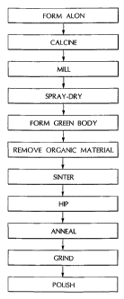
Fig. 1 is a block diagram of a method for making an aluminum oxynitride (AION)
structure;
Fig. 2 is a schematic diagram of an embodiment of a system for making A.ION;
Figs. 3A-B are cut-away perspective views of embodiments of retorts;
Fig 4 is a schematic diagram of an embodiment of a system for making AION
having
a plunger in an extended position;
Fig. 5 is a schematic diagram of an embodiment of a system for making AlON
having
a plunger in a retracted position;
Fig. 6 is a schematic diagram of an embodiment of a system for making AION;
and
Fig. 7 is a schematic diagram of an embodiment of a system for making AlON.
_~,_
CA 02415948 2003-01-17
WO 02/06156 PCT/US01/40614
DETAILED DESCRIPTION
Fig. 1 shows a method of making an AION structure, e.g., an AION dome.
Generally,
AION powder is formed by reacting A1203 and carbon in a nitrogen atmosphere at
high
temperatures. The formed A1ON powder is calcined to remove unreacted carbon
and milled
to reduce the particle size of the AION powder. The milled AION is then
sprayed dried to
agglomerate the A1ON particles and to form a flowable powder that can be
conveniently
poured into a mold to form a green body. The green body, having the
approximate size of
the structure, is formed by cold isostatic pressing. After pressing, the green
body is heated to
remove organic material, sintered to densify the structure, and further
densified by hot
isostatic pressing. The structure is then annealed and finished to the
structure's final
tolerances by grinding and polishing.
Referring to Fig. 2, the AION powder is here formed by a batch rotary process.
A
batch rotary system 10 includes a furnace 20, a cylindrical graphite chamber,
here a retort 30
inside furnace 20, and a flow tube 35 for delivering nitrogen gas into retort
30. Retort 30 is
connected to a drive motor 40 via a drive shaft 50 so that motor 40 can rotate
retort 30.
Retort 30 also defines a plurality of agitator or lifter bars 60 (shown in
Figs. 3A-B) on the
interior surface of retort 30. Lifter bars 60 are ridges or bumps integrally
formed with retort
30 that extend or spiral along the length of retort 30. Furnace 20 and retort
30 are available
from Centorr Vacuum Industries (Nashua, NH).
Generally, as retort 30 rotates, lifter bars 60 help to disperse a reaction
mixture 70 of
alumina and carbon within retort 30 by lifting and allowing reaction mixture
70 to fall inside
retort 30. It is believed that tumbling mixture 70 during reaction exposes
fresh, unreacted
mixture 70 to nitrogen, thereby aiding diffusion of nitrogen and shortening
the reaction time
needed to from AION.
Reaction mixture 70 is formed by mixing alumina with carbon. Typically,
reaction
mixture includes between about 4.5 to about 8% by weight carbon, and more
preferably
between about 4.5% to about 6.5% by weight carbon. The alumina is a gamma-
A1203
available from, e.g., Condea Vista (Tucson, AZ), although other forms of
alumina, such as,
for example, alpha- A1203 may be used. The carbon is a pure (dry) carbon
black, e.g.,
Monarch 880, available from Cabot Corp. (Billerica, MA). Other grades of
carbon black
may also be used. Preferably, the moisture content and volatile content of the
alumina and
-4-
CA 02415948 2003-01-17
WO 02/06156 PCT/US01/40614
the carbon are accurately known so that the carbon content in mixture 70 can
be controlled
within prescribed limits.
A homogeneous mixture of alumina and carbon is preferred so that a uniform
composition of A1ON can be formed. The alumina and carbon can be dry blended
by mixing
in a blender, ball milled (dry or wet), and/or shaken in a mixer (e.g., in a
paint shaker).
Preferably, the carbon is a carbon ink, which is convenient to handle and
provides good
mixing with the alumina. The carbon ink is formed by mixing carbon black with
water or an
organic solvent, such as methanol, ethanol, and propanol. A dispersant, such
as, for example,
Disperbyk 190 or 191, available from, e.g., BYK-Chemie, is added to the ink to
wet the
carbon black and to help keep the carbon black in suspension. Carbon ink is
also
commercially available from, e.g., Sun Chemical (Winston-Salem, NC) and Borden
Chemical Inc. (Cincinnati, OH). Preferably, the carbon ink solution is formed
and/or diluted
to form a solution having between about 5 and about 10% by weight carbon to
provide
uniforrri wetting of the alumina.
' The alumina and carbon ink are mixed in a cone blender having an intensifier
blade
or bar for about 30 to 90 minutes, or until reaction mixture 70 is blended and
uniform. A
typical charge for mixing is 15 kg, although the size of charge is a function
of the equipment
used. The liquid (e.g., water and solvent) is removed by evaporation prior to
charging retort
30, preferably in the same cone blender used for mixing. Alternatively, the
mixture of
alumina and carbon ink can be spray dried to form a free-flowing powder prior
to charging.
A charge of reaction mixture 70, e.g., about 500 g, is then placed in retort
30 by removing an
end cap (not shown) of retort 30, charging retort 30, and placing the end cap
back on retort
30.
After placing a charge of reaction mixture 70 in retort 30, retort 30 is
evacuated of air
and purged with high purity nitrogen gas. Generally, the nitrogen gas flow
rate must be
sufficient to restrict the carbon monoxide or carbon dioxide local
concentrations from
poisoning of the A1ON reaction. Suitable gas flow rates depend on the size of
the reaction
retort and the mass of the mixture 70 being processed. For mixtures 70 of
about 5 to about
20 kg, the nitrogen flow rates are about 2 to about 20 L/min.
Retort 30 is then rotated by activating drive motor 40, and reaction mixture
70 is
heated. The rotation speed is about 2-50 rotations per minute. The effect of
the rotation is to
-5-
CA 02415948 2003-01-17
WO 02/06156 PCT/US01/40614
disperse the alumina/carbon particles in the chamber and enable the nitrogen
gas to pass
around the dispersed particles and thereby facilitate the reaction between the
alumina/carbon
particles and the nitrogen. Accordingly, the rotation speed should be fast
enough to disperse
reaction mixture 70 inside retort 30, but not so fast that reaction mixture 70
is centrifuged
inside retort 30, thereby preventing the reaction mixture from tumbling.
Reaction mixture 70
is heated in the chamber at ramp rate of greater than 10-20 C/min to a soak
temperature of
about 1700-1900 C, preferably about 1825 C. The soak time is about 10-30
minutes,
preferably about 15 minutes. After reaction mixture 70 has soaked at the
predetermined soak
temperature and for the predetermined soak time, furnace 20 is turned off, and
reaction
mixture 70, now AION powder, is allowed to cool, typically taking about 4
hours. The
cooled AION powder is removed from retort 30, and another charge of reaction
mixture 70 is
added to retort 30 to form another batch of A1ON.
Thus, rotary system 10 described above is used as part of a batch process.
Each batch
of AION powder is formed by loading reaction mixture 70 in retort 30, heating
mixture 70,
cooling mixture 70, and removing formed A1ON from retort 30. For every batch
of A1ON
powder formed, furnace 20 is heated and cooled.
In another method of forming AION, the AION powder is formed by a semi-
continuous rotary process in which the fiunace is held at a constant soak
temperature for
multiple batches of AION. Referring to Fig. 4, a semi-continuous rotary system
100 includes
a furnace 110, a feed hopper 140, a graphite retort 120 inside furnace 110, a
drive motor 130,
and a collection hopper 160. Furnace 110 includes a nitrogen inlet 112 and a
nitrogen outlet
114. When furnace 110 is in use, nitrogen gas flows from inlet 112, through
retort 120, and
is vented through outlet 114. Feed hopper 140 includes a valve 145 and is used
for supplying
a reactant mixture 150 (similar to mixture 70) to retort 120. Retort 120,
similar in
construction to retort 30, is angled downwardly from hopper 140 and is
rotatable inside
furnace 110 via drive motor 130. Retort 120 includes a graphite plunger 125
moveably
located, e.g., extendable to a plurality of positions, inside retort 125.
Retort 120 also includes
an opening 180 for removing formed AION powder, as described below. Collection
hopper
160 is used for receiving formed A1ON powder 170. Because collection hopper
160 receives
hot A1ON powder 170, the interior surface of drum 160 is made of a non-
contaminating
-6-
CA 02415948 2003-01-17
WO 02/06156 PCT/US01/40614
material or refractory, such as, for example, alumina and graphite. Rotary
system 100 is
available from Centorr Vacuum Industries and Harper International (Lancaster,
NY).
In operation, furnace 110 is heated to the soak temperature (e.g., about 1700-
1900 C)
and retort 120 (with agitator bars, not shown) is rotating. Here again the
retort, or chamber
action causes the alumina/carbon particles to disperse. Nitrogen gas flows in
inlet 112 and
out outlet 114. Plunger 125 is extended past opening 180 so that when reactant
mixture 150
is charged into retort 120, mixture 150 is retained in retort 120. Reactant
mixture 150,
generally the same as reactant mixture 70, is charged into retort 120 from
hopper 140 by
opening valve 145 until a predetermined amount of mixture 150 is in retort
120. Reaction
mixture 150 is dispersed in retort 120 and allowed to react, e.g., for about
10-30 minutes.
Thus, here again the nitrogen is able to pass around the dispersed alumina
particles
After mixture 70 has reacted to form AION powder, plunger 125 is retracted
(Fig. 5)
so that the A1ON powder can flow through opening 180 and into collection drum
160. The
temperature of retort 120 is still at the soak temperature. Plunger 125 is
then repositioned,
e.g., extended past opening 180 (Fig. 4), and another batch of A1ON powder can
be formed
by charging reactant mixture 150 into retort 120 from hopper 140. Thus, in
this semi-
continuous process, multiple batches of AION can be formed without having to
turn furnace
110 on and off for each batch of A1ON. This process can shorten the time
needed to
synthesize multiple batches of A1ON by reducing the time needed to ramp the
furnace to the
soak temperature, the time needed for the furnace to cool, and the time needed
to charge the
retort and to remove the formed AION from the retort.
In another method of forming A1ON, the A1ON powder is formed by a continuous
rotary process. Referring to Fig. 6, a continuous rotary system 300 includes a
furnace 110, a
graphite retort 120 inside furnace 110, a drive motor 130, and a collection
hopper 160 for
collecting the product mixture 170 (formed AION). System 300 further includes
a feeder
310, a feed hopper 320, a load-lock hopper 330, and a gate valve 340 between
feed hopper
320 and load-lock hopper 330. Retort 120 is similar in construction to the
retorts described
above, e.g., angling downwardly from feeder 310 and rotatable inside furnace
110 via drive
motor 130. Furthermore, retort 120 of system 300 is constructed with
sufficient length such
that as reaction mixture 150 travels from input end 350 of retort 120 to
output end 360 of
retort 120, the residence time of mixture 150 in heated retort 120 is
sufficient for mixture 150
-7-
CA 02415948 2003-01-17
WO 02/06156 PCT/US01/40614
to form AION. In other words, retort 120 is made sufficient long such that
reaction mixture
150 that is introduced into retort 120 from feeder 310 is converted into A1ON
170 by the time
the reaction mixture reaches opening 180.
In operation, furnace 110 is heated to the soak temperature and retort 120 is
rotating
to disperse the alumina/carbon particles that are introduced into retort 120.
Nitrogen gas
flows in inlet 112 and out outlet 114. With gate valve 340 closed, reactant
mixture 150 is
loaded into load-lock hopper 330, which is evacuated of air and purged with
nitrogen.
Purging system 300 with nitrogen helps to prolong the life of the graphite
retort. Reactant
mixture 150 is then introduced into feed hopper 320 by opening gate valve 340.
Feed hopper
320 introduces mixture 150 into feeder 310, which introduces mixture 150 into
retort 120 at a
predetermined rate, e.g., volumetrically or gravimetrically. Feeder 310 can
be, for example,
a screw feeder and shaker feeder. As the charge in feed hopper 320 decreases,
more reactant
mixture 150 can be provided through load-lock hopper 330, as described above.
Feed hopper
320 can be made sufficient large to minimize the frequency at which hopper 320
needs to be
re-loaded.
Thus, by selecting the proper dimensions of retort 120 and adjusting the feed
rate of
reactant mixture 150, the temperature of the furnace 110, and rotation speed
of retort 120,
system 300 can produce a continuous output of AION. Other
experimental'parameters, e.g.,
nitrogen flow rate and particle size, can be adjusted to optimize output and
composition
uniformity.
Fig. 7 shows another embodiment of a continuous rotary process for making
A1ON.
System 400 is generally similar to system 300 but includes two feeding
assemblies 410 and
420 placed in parallel with retort 120, and two valves 430 and 440. Each
assembly 410 and
420 includes a feeder 310 and a feed hopper 320 generally as described above.
An exemplary operation of system 400 will now be described. With valves 430
and
440 closed, reactant mixture is introduced into feed hopper 320 of assembly
410, which is
then closed, evacuated and purged. Valve 430 is then opened for assembly 410
to introduce
reactant mixture into retort 120. Meanwhile, reactant mixture is introduced
into feed hopper
320 of assembly 420, which is then closed, evacuated and purged. When assembly
410 is
almost empty of reactant mixture, valve 440 is opened for assembly 420 to
introduce reactant
mixture into retort 120, and valve 430 is closed to load assembly 410 with
more reactant
-8-
CA 02415948 2003-01-17
WO 02/06156 PCT/US01/40614
mixture, as described above. When assembly 420 is near empty, valve 430 is
opened,
assembly 410 is again used to introduce reactant mixture into retort 120, and
valve 440 is
closed. The above-described procedure is repeated as needed.
Referring back to Fig. 1, the formed AION powder is removed from retort 30 or
collection hopper 160 and calcined to remove unreacted carbon. Calcining is
performed in
air or oxygen between about 700 and about 800 C. In an alternative
embodiment, collection
hopper 160 can be connected to a calcining fumace having flowing air or
oxygen.
Accordingly, hopper 160 can charge product mixture 170 (the formed AION)
directly into
the calcining furnace. In another embodiment, hopper 160 can be equipped with
flowing air
so that unreacted carbon can be removed as the formed A1ON powder cools to
between 700
and 800 C.
The calcined A1ON powder is ball milled to reduce the particle size of the
powder.
Ball milling is performed in polyurethane-lined, rubber-lined, or AION-lined
mills using
methanol as a milling fluid, and an alumina or A1ON grinding media, e.g.,
pellets. Milling
time is about 20-30 hours, typically about 24 hours. This produces an AION
powder having
a particle size less than about 8 microns, typically having an average
particle size less than 3
microns. The milled powder is placed in a rotary evaporator to remove the
milling fluid
(methanol). Calcined AION powder can also be ball milled using water in the
place of
methanol. The milled slurry can then be spray dried to form a dried powder or
slip cast into
shapes.
The A1ON powder, milled in methanol and dried in a rotary evaporator, is then
reconstituted with water, a dispersant agent (such as Duramax D3005 (Rohm and
Haas,
Philadelphia, PA)), and preferably a binder (such as Duramax B 1020) to form a
slurry.
Adding the binder typically provides strong AION structures with high and
uniform green
body density that can be made in different shapes. The slurry is spray dried
to agglomerate
the AION powder into particles about 100 microns in size. This produces a free-
flowing
powder having a uniform fill density that can be easily poured into a mold.
The AION powder is then formed into a green body. The AION powder is poured
into a rubber mold having a predetermined shape, agitated to uniform fill
density, and cold
isostatically pressed at pressures greater than 15,000 psi to produce a green
body to be used
in sintering (described below). Formation of the green body can include other
techniques
-9-
CA 02415948 2003-01-17
WO 02/06156 PCT/US01/40614
such as, for example, slip casting, and injection molding. The green body
typically has a
density of about 60% of the theoretical density and is formed about 20%
oversized of the
finished structure to compensate for shrinking from sintering and hot pressing
operations
(e.g., hot isostatic pressing, uniaxial hot pressing, and multiaxial hot
pressing), as described
below. After cold pressing, the green body is slowly heated to about 500-750
C in air to
remove residual organic material, e.g., the binder. If no binder was added to
the
reconstituted, milled powder, the slow heat treatment described above (500-750
C in air) can
be omitted. The formed green body is then placed in a graphite, alumina, or
A1ON container,
which is then placed in a sintering furnace.
The A1ON green body is sintered to remove and to close its porosity and to
increase
its density. Sintering is performed in a flowing or static atmosphere of
nitrogen for about 6-
10 hours, typically about 8 hours. Final sintering temperatures are higher
than 1900 C, but
lower than the melting temperature of A1ON, which is approximately 2140 C.
Sintering
produces a polycrystalline body having an average grain size of less than
about 20 microns.
The sintered body typically has a density of about 95-99% of the theoretical
density, or about
3.5 g/cc to about 3.7 g/cc.
The sintered body is then hot isostatically pressed (HIP) to further increase
its
density. Hot isostatic pressing is performed at about 1900 C and about 20,000-
30,000 psi,
preferably about 28,000-30,000 psi, in a convective argon or nitrogen
atmosphere for about
6-20 hours. This produces a body having an average grain size of about 100-350
microns,
and a density of about 100% of the theoretical density. After hot isostatic
pressing, the body
has the appearance of light gray to dark, tinted glass.
To obtain a "water clear" structure, the hot isostatically pressed A1ON body
is heat
treated in a flowing nitrogen atmosphere enclosed in an alumina or A1ON
crucible (to
provide a low partial pressure of oxygen and to avoid reducing the formed
A1ON) at about
1900 C for about 6-10 hours, typically 8 hours.
The heat treated body is finished to the structure by optical grinding and
polishing to
the final tolerances of the structure.
Other embodiments of the above-described methods are possible. For example, in
addition to or as an alternative to hot isostatic pressing, sintering aids, in
the form of small
amounts (<0.5 wt percent) of doping additives, can be added to the A1ON
powder. The aids
-10-
CA 02415948 2008-07-28
78,25-11
can include an element such as yttrium and lanthanum, or compounds thereof.
Other
lanthanides and their compounds, preferably the oxides, may also be used. A
combination of
the doping additives may also be used. A preferred combination includesØ08
wt % Y203
and 0.02 wt % La203. The doping additives may be added, e.g., during the ball
milling step.
Other methods of forming A1ON and AION structures, e.g. by carbothermal
nitridation, are described in U.S. Patent Nos. 4,520,116; 4,686,070;
4,720,362; 4,481, 300;
and 5,135,814 .
Other embodiments are within the claim.s.
What is claimed is:
-11-