Note: Descriptions are shown in the official language in which they were submitted.
CA 02416018 2003-01-28
WO 02/02914 PCT/US01/20574
ENGINE COVER
10 FIELD OF THE INVENTION
The field of the invention relates to internal combustion engines, more
particularly to housings for covering compact internal combustion engines,
such as
those used in lawn mowers, snow blowers, generators and the like.
DESCRIPTION OF THE BACKGROUND ART
Internal combustion engines are used to convert chemical energy to
mechanical or electrical energy for a wide variety of applications. Some
internal
combustion engines are compact and have one or two small cylinders for use in
low to
moderate power applications, while others have a higher number of large
cylinders for
use in high power applications. Engines of any type or size generate a great
deal of
heat due to the combustion process. Large engines, such as in an automobile,
are
typically enclosed in an isolated area, such as under the hood and in front of
a firewall
of a car. - As such, large engines are ordinarily out of reach of their users
or passers-
by. However, compact engines are typically used in devices, such as lawn
mowers, in
which the engines are openly accessible. Thus, compact internal combustion
engines
often have a guard or shield over the engine to reduce the risk of someone
contacting
a hot engine and being burnt.
In some cases, such as in lawn mowers, the engine is partially or totally
covered by a housing usually made of plastic or some other non-conducting
material.
Engines have a number of sub-assemblies and systems that may also radiate
heat.
Typically, separate housings cover, for example, the air filtration system and
the
cooling system. Additionally, baffles to direct air to the engine cooling
system and air
1
CA 02416018 2006-10-02
intake are usually attached to the housing. Each of these housings and baffles
require fastening systems, which increases part count and complexity of
manufacture and assembly. The plurality of housings typically must be
disassembled and reattached using tools. Moreover, the housings for sub-
systems are often nested beneath the main or other housings, such that
multiple housings may have to be removed to access a single sub-system.
Multiple housings and cumbersome fastening systems render servicing the
engine and its subassemblies difficult.
Accordingly, an improved housing for a compact internal combustion
engine is needed.
BRIEF SUMMARY OF THE INVENTION
The present invention provides in a housing for an internal combustion
engine disposed within an engine cavity defined by a fixed engine cradle, the
improvement comprising: a cover having a top side and downwardly
extending side walls sized to cover the engine cradle, one of the side walls
defining a recessed groove opening to the outside of the cover and extending
from a bottom edge to a catch; and a strap stretchable within the recessed
groove between a fixed end attached to the engine cradle and a free end
removably engageable with the cover catch under tension so as to bias the
cover towards the engine cradle and secure the cover to the engine cradle.
The present invention also provides a housing for an intemal combustion
engine, comprising a fixed cradle containing the engine and a cover having a
top side and integral side walls for enclosing the cradle, the cover having a
catch for releasable engagement with a stretchable strap mounted at one end
to the cradle for securing the cover to the cradle, wherein the cover
integrally
including an air baffle at the top side having a nozzle defined by a convex
circumferential surface having a narrowing diameter from top to bottom such
that air drawn into the housing through the nozzle is essentially non-
turbulent.
Removing the cover allows access to multiple systems of the engine
needed to be maintained. The covered is held to an engine cradle or mounting
2
CA 02416018 2006-10-02
frame by resilient straps allowing the cover to be assembled and removed
easily without the use of tools.
The strap is preferably a rubber material and the free end preferably
includes a tab that engages the catch. The tab has a projecting end for
grasping the strap to engage and disengage the strap from the cover. The
strap is stretchable and sized so that it is under tension when engaged with
the
catch so as to bias the cover toward the engine cradle. in one embodiment,
the cover includes a plurality of recessed grooves each retaining a
stretchable
strap for securing the cover to the engine cradle.
The cover preferably includes a baffle at the top side defining a convex
opening having smooth inwardly tapered walls to direct air into the housing in
an essentially non-turbulent condition. Curved raised surfaces in the baffle
serve to direct air into the opening. In one embodiment, a bezel attached to
the
top side of the cover retains a screen for covering the opening. The cover -
encloses an engine air filter and includes a hold-down extending down from the
top side of the cover for limiting the movement of the air filter. Preferably,
the
cover is a glass-filled polypropylene material.
The engine housing allows easy access to the engine. This is
accomplished by the single cover enclosing the entire engine. Because the
entire engine is enclosed by a single cover, additional covers are not
required
for sub-systems of the engine. This also allows an operator to quickly and
easily examine at a glance parts of the engine other than the area being
serviced. The cover can be assembled and removed without using tools.
In a preferred embodiment, the housing provides increased air flow to
the engine. This is accomplished by directly air to the engine cooling system
in
an essentially non-turbulent state. The convex opening in the top of the cover
acts as a venturi opening providing high-speed laminar air flow to the engine.
In a preferred embodiment, the housing helps to secure a removable air
cleaner. This is accomplished by a vertical wall integrally depending from the
top of the cover to restrain the movement of the air cleaner.
The cover may be made of a glass-filled polypropylene making it durable
and resistant to thermal conduction.
The foregoing and other features and advantages of the invention will
appear from the following description. In the description, reference is made
to
3
CA 02416018 2006-10-02
the accompanying drawings which form a part hereof, and in which there is
shown by way of illustration a preferred embodiment of the invention.
BRIEF DESCRIPTION OF THE DRAWINGS
Figure 1 is a perspective view of an internal combustion engine housing
according to the present invention;
Figure 2 is a top view of a cover of the engine housing of Figure 1,
shown without a removable bezel and screen;
Figure 3 is an assembly view of the engine housing of Figurel;
Figure 4 is a cross-sectional view taken along line 4-4 of Figure 1,
showing the connection of the straps;
Figure 5 is a cross-sectional view similar to Figure 4 with the cover
removed, and
Figure 6 is a cross-sectional view taken along line 6-6 of Figure 1,
showing an engine air cleaner contained within an air cleaner cover having an
integral hold-down.
DETAILED DESCRIPTION OF THE PREFERRED EMBODIMENTS
The housing of the present invention is referred to throughout the
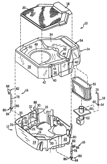
drawings by reference number 10. Referring to Figure 1, generally the housing
includes an engine cradle 12 defining a cavity for containing a compact
internal combustion engine, as
4
CA 02416018 2003-01-28
WO 02/02914 PCT/US01/20574
are known in the art. A cover 14 is attached to the cradle 12 by a plurality
of straps
16. A bezel 18 snaps onto the cover 14 so as to retain a'screen 20.
Referring to Figs. 1 and 3, the cradle 12 is preferably molded of a glass-
filled
nylon to include a bottom framework 19 and upstanding side 22 and end 24
walls.
Each sidewa1122 has two pairs of ridges 26 projecting from their inner
surfaces
forming slots 28. Above each slot is a notch 30 at a top edge 32 of the cradle
sidewalls 22. The cover 14 is molded of a glass-filled polypropylene to
include a
baffle 34 at a top side with side 36 and end 38 walls extending downwardly
along the
perimeter of the baffle 34 sized to overlap the cradle 22 and 24 walls and
encapsulate
the engine (not shown). The cover sidewalls 36 are formed to include two
parallel
longitudinal recesses 40 each extending from a bottom edge 42 of the sidewalls
36 to
a recessed catch 44. The recesses 40 are positioned to be aligned with the
cradle slots
28 when the cover 14 is assembled to the cradle 12.
Referring to Figs. 2 and 3, the cover baffle 34 includes a winged opening
(shown in phantom) 46 providing clearance for a radiator fill neck (not shown)
and
engine air hoses (not shown). The baffle 34 also forms a smooth convex opening
48,
having a circular cross-section. The convex opening 48 has a gradually
decreasing
circumference from outside to inside the cover 14. This convex opening 48
provides
a venturi effect, as known in the art, providing a smooth, essentially not
turbulent
transition flow past the cover 14. This allows air to be at a relatively high
velocity
laminar flow as it enters the intake centrifugal fan (not shown), thereby
increasing air
flow to the engine and increasing fan efficiency, as is understood by those
skilled in
the art. Smooth, wavy raised surfaces 50 are formed in the cover 14 around the
convex opening 48 to aid in directing air therethrough.
'S Referring to Figs. 2 and 3, the screen 20, preferably made of a polymer-
coated
steel wire mesh, is secured over the winged opening 46 and the convex opening
48 to
prevent debris from entering the housing 10 and the engine intake. As
mentioned, the
screen 20 is held in place by the bezel 18. The bezel 18 is preferably made of
a glass-
filled polypropylene material and is snapped onto the cover 14 by four clips
52
(shown in phantom in Fig. 2) integrally formed in the cover 14. The clips 52
can be
5
CA 02416018 2003-01-28
WO 02/02914 PCT/US01/20574
depressed so as to remove the beze118, and thereby the screen 20, from the
cover 14.
This allows the screen 20 to be cleaned, repaired or replaced without using
tools.
Referring to Figs. 2, 3 and 6, a tabbed end 54 of the cover 14 encloses a
removable air cleaner 56 secured to the cradle 12 by an air cleaner tie-down
58
attached at a bottom end 60 to an air intake elbow 62 via a tab 64 and slot 66
arrangement. Referring to Fig. 6, a catch 68 at the top end 70 of the air
cleaner tie-
down 58 engages a recess 72 in the top of the air cleaner 56. The catch 68 can
be
disengaged by pulling up at a grip 74 at the top of the air cleaner tie-down
58. The air
cleaner tie-down 58 is preferably a rigid plastic. Additionally, the cover 14
is formed
to include a downwardly depending wall 76 positioned to be above the air
cleaner 56
when the cover 14 is assembled to the cradle 12. The wal176 acts as a
secondary
hold-down for restricting the movement of the air cleaner 56.
Referring again to Fig. 3, the, straps 16, preferably a resilient material,
such as
rubber, each have an elongated body 78 extending between a fixed end 80 and a
free
end 82. The fixed end 80 has a balled tip 84 and a squared shoulder 86 for
engaging
the cradle 12. The free end 82 has a tapered tab 88 extending generally
transversely to
the body 78 for grasping when stretching the straps 16 to assemble or remove
the
cover 14. The straps 16 can be separated from the cradle 12 for replacement if
needed.
Referring to Fig. 4, the straps 16 are attached to the cradle 12 by inserting
the
fixed ends 80 through recessed openings 90 in the sidewalls 22 so that the
strap
shoulders 86 engage bottom surfaces 92 of the cradle sidewalls 22. The
elongated
bodies 78 are then fit within the slots 28 in the cradle 12 and bent outward
through the
notches 30 so that the strap tabs 88 are outside of the cradle 12.
Referring to Figs. 4 and 5, the cover 14 is assembled to the cradle 12 by
lapping the cover walls 36 and 38 over the cradle walls 22 and 24 so that the
cover
recesses 40 align with the notches 30 in the cradle 12 that hold the free ends
82 of the
straps 16. With the cover 14 in place, one by one each strap 16 is pulled up
and out
by the tab 88 so that the tab 88 engages the catch 44 in the cover 14. When
the free
end 82 is engaged as shown in Fig. 5, the strap bodies 781ie in the recesses
40 of the
6
CA 02416018 2003-01-28
WO 02/02914 PCT/US01/20574
cover 14. In this position, the resilience of the straps 16 bias the cover 14
downwardly against the cradle 12.
Thus, the present invention provides a durable engine housing that shields the
operator from the engine and is resistant to thermal conduction. At the same
time, the
housing facilitates easy access to the engine by using a single cover to
enclose the
entire engine, thereby eliminating the need for additional covers for sub-
systems of
the engine, such as an air cleaner. This feature also allows =an operator to
quickly and
easily.examine parts of the engine other than the area being serviced.
Moreover, the
cover can be removed without using tools.
While there has been shown and described what are at present considered the
preferred embodiment of the invention, it will be obvious to those skilled in
the art
that various changes and modifications cari be made therein without departing
from
the scope of the invention.
7