Language selection

Search

Patent 2416044 Summary

Third-party information liability

Some of the information on this Web page has been provided by external sources. The Government of Canada is not responsible for the accuracy, reliability or currency of the information supplied by external sources. Users wishing to rely upon this information should consult directly with the source of the information. Content provided by external sources is not subject to official languages, privacy and accessibility requirements.

Claims and Abstract availability

Any discrepancies in the text and image of the Claims and Abstract are due to differing posting times. Text of the Claims and Abstract are posted:

  • At the time the application is open to public inspection;
  • At the time of issue of the patent (grant).
(12) Patent: (11) CA 2416044
(54) English Title: DISPLAY DEVICE FOR A PORTABLE DATA CARRIER
(54) French Title: DISPOSITIF D'AFFICHAGE DESTINE A UN SUPPORT DE DONNEES PORTABLE
Status: Deemed expired
Bibliographic Data
(51) International Patent Classification (IPC):
  • G06K 19/07 (2006.01)
  • G06K 19/077 (2006.01)
(72) Inventors :
  • GRAF, HANS (Germany)
  • HOHMANN, ARNO (Germany)
(73) Owners :
  • GIESECKE & DEVRIENT GMBH (Germany)
(71) Applicants :
  • GIESECKE & DEVRIENT GMBH (Germany)
(74) Agent: RIDOUT & MAYBEE LLP
(74) Associate agent:
(45) Issued: 2007-01-30
(86) PCT Filing Date: 2001-07-16
(87) Open to Public Inspection: 2003-01-13
Examination requested: 2003-11-13
Availability of licence: N/A
(25) Language of filing: English

Patent Cooperation Treaty (PCT): Yes
(86) PCT Filing Number: PCT/EP2001/008196
(87) International Publication Number: WO2002/007079
(85) National Entry: 2003-01-13

(30) Application Priority Data:
Application No. Country/Territory Date
100 35 094.1 Germany 2000-07-17

Abstracts

English Abstract


The invention relates to a portable data carrier having a display device. This
data
carrier contains a microprocessor and storage devices associated with the
microprocessor as well as means for displaying data stored in the storage
devices
associated with the microprocessor. In addition, the data carrier contains a
display
controller for controlling the display means and an energy supply unit for
supplying at
least the display unit and its controller with energy. Such a data carrier is
to be
improved so as to reduce the energy demand for the display unit. This is
obtained by a
nonvolatile memory disposed separately from the microprocessor and its storage
device, said memory being associated with the controller of the display means
and
containing the data intended for display.


French Abstract

L'invention concerne un support de données portable comportant un dispositif d'affichage. Ledit support de données comporte un microprocesseur, des unités mémoire affectées au microprocesseur, ainsi que des moyens d'affichage de données stockées dans les unités mémoire affectées au microprocesseur. Ledit support de données comporte par ailleurs une unité de commande d'affichage destinée à commander les moyens d'affichage, ainsi qu'une unité d'alimentation alimentant au moins l'unité d'affichage et l'unité de commande associée en énergie. L'invention vise à réduire la consommation d'énergie de l'unité d'affichage sur un tel support de données. A cet effet, le support de données selon l'invention comporte une mémoire non volatile séparée du microprocesseur et de l'unité mémoire associée à celui-ci, ladite mémoire étant affectée à l'unité de commande des moyens d'affichage et contenant les données destinées à l'affichage.

Claims

Note: Claims are shown in the official language in which they were submitted.


-6-

Claims

1. A portable data carrier having a display device comprising
- a microprocessor and storage devices associated with the microprocessor,
- means for contactless and/or contact-type coupling with external devices,
- means for displaying or selecting data stored in storage devices associated
with the microprocessor,
- a display controller for controlling the display device,
- an energy supply unit for supplying the display device and the display
controller with energy,
- a nonvolatile memory disposed separately from the microprocessor and its
associated storage device, said memory being associated with the display
controller and containing the data intended for display in order to display
data in connection with the energy supply unit without operation of the
microprocessor.

2. A portable data carrier according to claim 1, wherein the display
controller is
supplied by a separate clock generator with a system clock having a lower
frequency than the system clock of the microprocessor.

3. A portable data carrier according to claim 1 or 2, wherein the nonvolatile
memory associated with the display controller has a buffer upstream thereof.

4. A portable data carrier according to any of claims 1 to 3, wherein the
microprocessor and its associated storage device are provided to form an
electronic purse and the separate memory associated with the display
controller
stores the current amount present in the purse and previous transaction data.

5. A portable data carrier according to any of claims 1 to 4, wherein the
display
controller is actuated by a switch.


-7-

6. A method for operating an electronic purse, wherein
- before termination of a transaction the transaction data are copied from the
memory of the purse chip to a separate, nonvolatile memory associated with
a display unit, the nonvolatile memory and the display controller as well as
a display device being disposed on a card also containing the purse chip,
and the card having a separate energy supply for the display device and
display controller so that data can be displayed independently of operation
of the purse chip,
- after termination of the copying operation a first acknowledge signal is fed
from the display controller to the purse chip,
- after receiving the first acknowledge signal the purse chip in turn sends a
second acknowledge signal to the terminal, and
- after receiving the second acknowledge signal the terminal asks the user to
remove the card by means of an optical or acoustic display.

Description

Note: Descriptions are shown in the official language in which they were submitted.


CA 02416044 2003-O1-13
Display device for a portable data carrier
This invention relates to a portable data carrier having a display device
according
to the generic part of claim 1.
German laid-open print DE-A 42 03 748 discloses a method for utilizing and
evaluating rechargeable smart cards wherein payments by means of a smart card
are
recorded in a nonvolatile memory of the card. At each charging, the preceding
payment transactions are erased and the available credit balance stored. It is
in
particular provided that the most recently inputted or most recently debited
value is
indicated on a display located on the card. Such a method or device is
intended to
increase the acceptance of purse smart cards since the user has at least a
certain
possibility of checking his current credit balance or the most recent
transaction.
Further, from German laid-open print DE-A 196 31 557 discloses a display unit
for a smart card. Here, too, the display of the current credit balance is
intended to
increase the acceptance of purse smart cards. The presented smart card has a
smart
card processor with terminals as well as a magnetic stripe and a field for an
embossing
as is usual in cards. Further, a display controller is implemented as a
separate unit for
controlling the display. For the power supply required for the display, a
solar cell is
provided.
A smart card having a display and solar cell or battery according to the
generic
part of claim 1 is in addition known from European laid-open print EP-A 0 299
414 as
well as from patent prints US-C 4 827 111, US-C 4 924 075 and US-C S 438 679.
The disadvantage of known smart cards is that the power supply causes a
problem on a smart card because of the low capacity of the available energy
sources.
In particular, it has proved problematic that due to the comparatively high
clock
frequency of the card microprocessor, which must be at least one megahertz for
safety
reasons, high current consumption considerably restricts the service life of
the energy
source or makes it very difficult or impossible to use a solar cell, for
example, in smart
cards.


-2-
It is therefore the problem of the invention to state a portable data carrier
having
a display device that has a low energy demand in particular for the display
control or
data storage.
This problem is solved, starting out from the features of the generic part of
claim
l, by the characterizing features of claim 1. A method for operating an
electronic purse
according to the invention is stated in claim 6.
Advantageous embodiments of the invention are stated in the dependent claims.
According to the invention it is provided that an additional memory is used
that
can be operated independently of the card microprocessor. This memory stores
those
data that are released for display. This additional memory is associated with
the
display controller and thus independent of the card microprocessor. In
particular it is
advantageous that the microprocessor does not have to be in operation for data
to be
displayed, i.e. the energy demand can be reduced since few functional units,
for
example clock generator, display control and storage device, have to be
supplied with
energy.
It has proved especially advantageous to provide the display controller and
thus
indirectly also the additional memory with a separate clock generator, the
system clock
generated by this clock generator having a lower clock frequency than the
system
clock of the microprocessor. This obtains a further reduction of the energy
demand for
displaying data.
It has further proved advantageous to connect a buffer upstream of the
nonvolatile memory. Since there is the possibility during transfer of the
display data
from the microprocessor to the additional memory of a user removing the card
from
the terminal while the data are being transferred to the additional memory,
the buffer
constitutes a safety stage preventing inconsistent data from being stored in
the
additional memory. The data are transferred from the buffer to the additional
memory
only when they have been completely transferred from the microprocessor
memory.
Data transfer from the microprocessor to the buffer is effected via the serial
interface
CA 02416044 2003-O1-13


-3-
according to the transfer protocol provided for the smart card. Transfer from
the buffer
to the additional memory can be effected via a parallel interface, which keeps
the time
for transferring data from the buffer to the additional memory very low.
Further, transfer can also be effected without energy supply by the terminal
since
S the energy source located on the card can be used for this purpose.
According to a further advantageous embodiment of the invention, the portable
data carrier is an electronic purse, i.e. a purse smart card, wherein the
additional
memory stores not only the current amount present in the purse but also
previous
transaction data, so that the latter can be called up by the user if required.
The display controller is preferably actuated by a switch, so that for example
at
one press on the switch the display unit is activated, and at each further
press on the
switch the previous transaction data are indicated on the display unit. The
display unit
is preferably switched off after relatively long nonuse of the switch.
The invention further provides a method for operating an electronic purse
according to claim 6. According to the inventive method, the transaction data
are
copied from the memory of the purse chip to the separate memory after
termination of
a transaction, which takes place according to the provided protocols like a
known
transaction. After termination of the copying operation to the separate
memory, the
display controller preferably feeds an acknowledge signal to the purse chip to
indicate
that the data have been completely transferred. After receiving this first
acknowledge
signal, the purse chip sends a second acknowledge signal to the terminal. The
terminal
in turn shows on an optical or acoustic display unit as a result of this
second
acknowledge signal a message asking the user to remove the card, after which
communication with the terminal is ended.
Hereinafter the invention will be explained in more detail with reference to
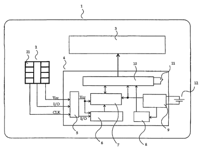
Figure 1 showing the basic structure of an inventive data Garner.
Figure 1 shows a smart card, preferably a purse smart card, containing purse
chip
2 disposed in a module with contact surfaces 21.
CA 02416044 2003-O1-13


-4-
Further, purse smart card 1 contains display unit 3 controlled by functional
unit 4
disposed separately from the purse chip. Functional unit 4 contains purse chip
interface 5 to which data input/output line IlO as well as clock supply line
CLK and
power supply line Ycc lead from the purse chip. From purse chip interface 5
connecting lines lead to buffer 6 and from there to nonvolatile separate
memory 7. If
buffer 6 is not provided, the connecting lines lead directly to additional
memory 7.
Buffer 6 is preferably executed as a RAM, while separate memory 7 is executed
as a
nonvolatile, preferably EZPROM, memory.
Nonvolatile memory 7 is connected with display controller 10 which in turn
controls display unit 3. The display unit can only display the data stored in
nonvolatile
memory 7 and thus released for display.
Power or clock supply is effected via analog interface 9 connected with energy
supply unit 12 disposed on the card. Energy supply unit 12 can also be applied
to the
analog interface via a switch. Energy supplied via the analog interface is
made
available to nonvolatile memory 7 as well as display controller 10 and clock
generator
8. Clock generator 8 serves display controller 10 as its clock supply. It is
essential to
the invention that controller 4 for controlling display unit 3 can also be
operated
without energy supply or without operation of the purse chip, i.e. without the
card
being introduced into a terminal, so that data can be indicated on the display
unit. The
independence of controller 4 lowers energy consumption and readily permits
energy
sources 12 to be used that supply display unit 3 and its controller 4 with
energy for the
life of card 1. Examples of energy sources to be mentioned are thin-film
batteries, flat
accumulators, piezoelectric elements or solar cells.
Clock generator 8 used for the clock supply of controller 10 of separate
memory
7 and optionally buffer 6 generates according to the invention a clock
frequency that is
preferably distinctly below the clock frequency of the purse chip. This
permits a
further reduction of energy consumption for the display unit and its
controller.
The purse chip interface has inputs Ycc for power supply, CLK for the external
clock and 1/O for the data. For data exchange the I/O interface is executed to
be
CA 02416044 2003-O1-13


-5-
bidirectional or unidirectional, whereby a plurality of I/O lines can also be
provided in
parallel.
In the unidirectional execution, data of the purse chip can be written to
memory 6
or 7 but rewriting of data to the purse chip is not possible. This prevents
manipulation
S of the data stored in the purse chip.
Bidirectional execution has the advantage, however, of permitting feedback
with
respect to the data copying operation from controller 4 to purse chip 2.
No additional security apparatus for data transfer is necessary since the data
indicated on the display unit, i.e. the data transferred to controller 4 from
the purse
chip, are not in need of being kept secret.
Via the I/O line the data intended for display are fed via purse chip
interface 5 to
buffer 6 or additional memory 7 after a transaction of the purse chip with the
terminal
is completed to the extent that the transaction data are updated on the purse
chip. Only
after complete transfer of the data to additional memory 7 or at least to
buffer 6 is the
terminal informed by an acknowledge signal that the transaction is completed.
CA 02416044 2003-O1-13

Representative Drawing
A single figure which represents the drawing illustrating the invention.
Administrative Status

For a clearer understanding of the status of the application/patent presented on this page, the site Disclaimer , as well as the definitions for Patent , Administrative Status , Maintenance Fee  and Payment History  should be consulted.

Administrative Status

Title Date
Forecasted Issue Date 2007-01-30
(86) PCT Filing Date 2001-07-16
(85) National Entry 2003-01-13
(87) PCT Publication Date 2003-01-13
Examination Requested 2003-11-13
(45) Issued 2007-01-30
Deemed Expired 2018-07-16

Abandonment History

There is no abandonment history.

Payment History

Fee Type Anniversary Year Due Date Amount Paid Paid Date
Application Fee $300.00 2003-01-13
Registration of a document - section 124 $100.00 2003-04-17
Maintenance Fee - Application - New Act 2 2003-07-16 $100.00 2003-06-25
Request for Examination $400.00 2003-11-13
Maintenance Fee - Application - New Act 3 2004-07-16 $100.00 2004-07-06
Maintenance Fee - Application - New Act 4 2005-07-18 $100.00 2005-06-16
Maintenance Fee - Application - New Act 5 2006-07-17 $200.00 2006-04-19
Final Fee $300.00 2006-11-16
Maintenance Fee - Patent - New Act 6 2007-07-16 $200.00 2007-05-23
Maintenance Fee - Patent - New Act 7 2008-07-16 $200.00 2008-07-02
Maintenance Fee - Patent - New Act 8 2009-07-16 $200.00 2009-07-07
Maintenance Fee - Patent - New Act 9 2010-07-16 $200.00 2010-07-06
Maintenance Fee - Patent - New Act 10 2011-07-18 $250.00 2011-07-04
Maintenance Fee - Patent - New Act 11 2012-07-16 $250.00 2012-07-03
Maintenance Fee - Patent - New Act 12 2013-07-16 $250.00 2013-07-02
Maintenance Fee - Patent - New Act 13 2014-07-16 $250.00 2014-07-02
Maintenance Fee - Patent - New Act 14 2015-07-16 $250.00 2015-07-02
Maintenance Fee - Patent - New Act 15 2016-07-18 $450.00 2016-07-05
Owners on Record

Note: Records showing the ownership history in alphabetical order.

Current Owners on Record
GIESECKE & DEVRIENT GMBH
Past Owners on Record
GRAF, HANS
HOHMANN, ARNO
Past Owners that do not appear in the "Owners on Record" listing will appear in other documentation within the application.
Documents

To view selected files, please enter reCAPTCHA code :


To view images, click a link in the Document Description column. To download the documents, select one or more checkboxes in the first column and then click the "Download Selected in PDF format (Zip Archive)" or the "Download Selected as Single PDF" button.

List of published and non-published patent-specific documents on the CPD .

If you have any difficulty accessing content, you can call the Client Service Centre at 1-866-997-1936 or send them an e-mail at CIPO Client Service Centre.


Document
Description 
Date
(yyyy-mm-dd) 
Number of pages   Size of Image (KB) 
Cover Page 2007-01-09 1 42
Claims 2003-01-13 2 60
Drawings 2003-01-13 1 14
Description 2003-01-13 5 238
Representative Drawing 2003-03-12 1 7
Cover Page 2003-03-13 1 41
Claims 2005-11-04 2 60
Abstract 2003-01-13 1 21
Fees 2004-07-06 1 33
PCT 2003-01-13 10 416
Assignment 2003-01-13 4 114
Correspondence 2003-03-10 1 24
Assignment 2003-04-17 2 90
Fees 2003-06-25 1 31
Prosecution-Amendment 2003-11-13 1 36
Prosecution-Amendment 2004-01-16 1 31
Fees 2006-04-19 1 27
Prosecution-Amendment 2005-05-13 2 58
Fees 2005-06-16 1 28
Prosecution-Amendment 2005-11-04 4 127
Correspondence 2006-11-16 1 27
Fees 2007-05-23 1 28
Fees 2008-07-02 1 34
Fees 2009-07-07 1 33