Language selection

Search

Patent 2416217 Summary

Third-party information liability

Some of the information on this Web page has been provided by external sources. The Government of Canada is not responsible for the accuracy, reliability or currency of the information supplied by external sources. Users wishing to rely upon this information should consult directly with the source of the information. Content provided by external sources is not subject to official languages, privacy and accessibility requirements.

Claims and Abstract availability

Any discrepancies in the text and image of the Claims and Abstract are due to differing posting times. Text of the Claims and Abstract are posted:

  • At the time the application is open to public inspection;
  • At the time of issue of the patent (grant).
(12) Patent: (11) CA 2416217
(54) English Title: TAPERED BOOM HOSE
(54) French Title: TUYAU CONIQUE DE COULAGE DU BETON
Status: Expired
Bibliographic Data
(51) International Patent Classification (IPC):
  • E04G 21/04 (2006.01)
(72) Inventors :
  • LEHNHARDT, GARY D. (United States of America)
  • ALTAMIRANO, ROLANDO (United States of America)
(73) Owners :
  • CONSTRUCTION FORMS, INC. (United States of America)
(71) Applicants :
  • CONSTRUCTION FORMS, INC. (United States of America)
(74) Agent: BORDEN LADNER GERVAIS LLP
(74) Associate agent:
(45) Issued: 2008-10-14
(22) Filed Date: 2003-01-13
(41) Open to Public Inspection: 2004-04-15
Examination requested: 2006-01-24
Availability of licence: N/A
(25) Language of filing: English

Patent Cooperation Treaty (PCT): No

(30) Application Priority Data:
Application No. Country/Territory Date
10/271,958 United States of America 2002-10-15

Abstracts

English Abstract

A concrete boom hose is provided with a first end that is connected to the outermost end of a series of concrete pipes and a second end through which the flowing concrete exits. The second end is provided with an inner diameter that is smaller than the inner diameter of the first end that is connected to the concrete pipe.


French Abstract

Le présent extrait concerne un tuyau de coulage de béton ayant une première extrémité qui est raccordée à l'extrémité la plus extérieure d'une série de tuyaux à béton et une deuxième extrémité par laquelle sort le béton coulant. La deuxième extrémité a un diamètre intérieur qui est inférieur au diamètre intérieur de la première extrémité qui est raccordée au tuyau à béton.

Claims

Note: Claims are shown in the official language in which they were submitted.


CLAIMS:

1. A boom hose for use in a concrete pumping system of the type utilizing a
concrete pump to provide a flow of concrete through a series of pipe sections
to a hose for
distribution of the concrete into a form or other area, said boom hose
comprising:
a length of flexible tubing having a first end coupled to the outer end of a
delivery
pipe, said first end having a first inner diameter,
and a second end from which the concrete flows, said second end having a
second
inner diameter with said second inner diameter being smaller than said first
inner
diameter,
said flexible tubing having a uniform and continuous taper along its entire
length
from said first inner diameter to said second inner diameter.

2. The boom hose defined in claim 1, wherein said second inner diameter is
substantially eighty percent of said first inner diameter.

3. The boom hose defined in claim 1 or 2, wherein said boom hose has a
length in excess of ten feet.

4. The boom hose defined in any one of claims 1 to 3, wherein said first inner

diameter is substantially five inches and said second inner diameter is
substantially four
inches.

5. A boom hose for use in a concrete pumping system of the type utilizing a
concrete pump to provide a flow of concrete through a series of concrete pipe
sections to a
hose for distribution of the concrete into a form or other area, said boom
hose comprising:
a length of flexible tubing having a first end coupled to the outer end of a
concrete
pipe, said first end having a first inner diameter and a second end from which
the concrete
flows,
said second end having a second inner diameter with said second inner diameter

being substantially eighty percent of said first inner diameter,
said flexible tubing having a uniform and continuous taper along its entire
length
from said first inner diameter to said second inner diameter.


-4-

Description

Note: Descriptions are shown in the official language in which they were submitted.


CA 02416217 2003-O1-13 w
TAPERED BOOM HOE
FIELD OF THE INVENTION
The present invention relates to boom hoses utilized in a concrete delivery
system.
BACKGROUND OF THE INVENTION
Typically, concrete is delivered at a job site to remote areas via a system
that pumps the concrete through a series of boom connected pipes terminating
in a
flexible delivery hose.
It is desirable to slow down the flow of concrete from the end of the boom
to the tip of the boom hose in order to reduce the force of free falling
poured concrete
and thus decrease the impact force against the walls of the concrete forms. It
is also
desirable to slaw down the flow of concrete in order to reduce the splashing
of concrete
around the area being poured and to better control the air content of the
poured concrete.
In the past, the flow of concrete has been slowed by utilizing a number of
methods. One such method was the use of a metal boom "reducer" (funnel). The
use of
a reducer and its associated coupling adds additional weight to the boom,
especially
when the reducer is full of concrete. With today's modern boom lengths, the
added
weight presents serious problems that often will require additional counter
weights to
2 o keep the concrete pumping truck balanced.
The flaw has else been slowed down by utilizing a "Ram's Horn" that
forces the flowing concrete through a spiral in order to slow it down.
The industry also utilizes a bend or kink in the hose in order to reduce the
inner diameter of the hose. '
2 ~ However, both of these methods have the drawback of disrupting the
smooth, even flow of the concrete.
It is the object of the present invention to provide a boom hose that slows
down the flow of concrete without the need of any additional equipment such as
a Ram's
Hom or metal reducer. It is also an object ofthe pxesent invention to provide
a boom
3 o hose that will slaw the flow of concrete and yet provide a smooth, even
flow to better
control the air content of the pumped concrete.
_1_

-- CA 02416217 2003-O1-13
BRIEF SIT~~11~IARY OF THE INVENTION
A boom hose for use in a concrete pumping system of the type utilizing a
concrete pump to provide the flow of concrete through a series of concrete
pipe sections
includes a flexible hose having a first end coupled to the outer end of a
concrete pipe,
with the first end having a first inner diameter.
In accordance with another aspect of the invention, the boom hose is
provided with a second end that has a second inner diameter that is smaller
than the first
inner diameter.
The present invention thus provides a boon. hose that slows the t~Iow of
1 o concrete from the end of the concrete pipe without the need of any
additional equipment
such as a Ram's Horn or metal reducer.
The present invention also provides a smooth, even flow of concrete from
the end of the hose by eiim.inating the free flow of concrete from the tip of
the boom to
the tip of the hose. The taper of the hose allows the hose. to remain full of
concrete for a
~5 longer period of time, thus providing a uniform, even flow.
Various other features, objects, and advantages of the invention will be
made apparent from the following detailed description and the drawings.
BRIEF DESCRIPTION OF THE DRAWINGS
The drawings illustrate the best mode presently contemplated of carrying
2 0 out the invention.
In the drawings:
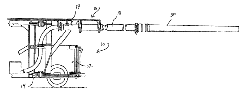
Fig. 1 is a side view of a concrete pumping system utilizing a boom hose
constructed according to the present invention;
Fig. 2 is a side view of a prior art boom hose;
2 5 Fig. 3 is a side view of a boom hose constructed according to the present
invention;
Fig. 4 is a cross-sectional view of the outer end of the boom hose; and
Fig. 5 is a cross-sectional view of the inner end of the boom hose.
DETAILED DESCRIPTION OF THE; INVENTION
3 o As shown in. Figure l, a concrete pumping system 10 includes a concrete
pump 12 mounted on a truck chassis 14.
Concrete is delivered to a remote site via a. concrete boom 16 comprised of


- CA 02416217 2003-O1-13 -
a series of interconnected c~ncrete pipes 18 terminating in a flexible boom
hose 20.
As shown in Figure 2, a prior art boom hose would have a uniform
diameter throughout its length.
In accordance with the present invention, as shown in Figures 3-5, boon
hose 20 is provided with a fret end 24 that is connected to concrete pipe 16
via pipe
coupling 26. First end 24 is provided with an inner diameter 30 of
approximately five
inches.
In accordance with the invention, boom hose 20 is provided with a second
end 28 through which the pumped concrete exits. Second end 28 is provided with
an
inner diameter 32 of appxoximately four inches so that the flow of concrete
from pipe 16
is slowed as it travels through boom hose 20.
Typically, boom hose 20 has a length of approximately twelve feet.
Obviously, the above referenced inner diameters and hose lengths can be varied
according to the requirements ofthe Sob as long as the inner diameter 32 of
hose tip 28 is
smaller than the inner diameter 30 of the hose at its connection point 24.
It is recognized that other equivalents, alternatives, and modifications
aside from those expressly stated, are possible and within the scope of the
appended
claims.
_3_

Representative Drawing
A single figure which represents the drawing illustrating the invention.
Administrative Status

For a clearer understanding of the status of the application/patent presented on this page, the site Disclaimer , as well as the definitions for Patent , Administrative Status , Maintenance Fee  and Payment History  should be consulted.

Administrative Status

Title Date
Forecasted Issue Date 2008-10-14
(22) Filed 2003-01-13
(41) Open to Public Inspection 2004-04-15
Examination Requested 2006-01-24
(45) Issued 2008-10-14
Expired 2023-01-13

Abandonment History

There is no abandonment history.

Payment History

Fee Type Anniversary Year Due Date Amount Paid Paid Date
Registration of a document - section 124 $100.00 2003-01-13
Application Fee $300.00 2003-01-13
Maintenance Fee - Application - New Act 2 2005-01-13 $100.00 2004-12-22
Maintenance Fee - Application - New Act 3 2006-01-13 $100.00 2005-12-20
Request for Examination $800.00 2006-01-24
Maintenance Fee - Application - New Act 4 2007-01-15 $100.00 2006-12-20
Maintenance Fee - Application - New Act 5 2008-01-14 $200.00 2007-12-20
Final Fee $300.00 2008-08-01
Maintenance Fee - Patent - New Act 6 2009-01-13 $200.00 2008-12-15
Maintenance Fee - Patent - New Act 7 2010-01-13 $200.00 2009-12-15
Maintenance Fee - Patent - New Act 8 2011-01-13 $200.00 2010-12-17
Maintenance Fee - Patent - New Act 9 2012-01-13 $200.00 2011-12-16
Maintenance Fee - Patent - New Act 10 2013-01-14 $450.00 2013-01-29
Maintenance Fee - Patent - New Act 11 2014-01-13 $250.00 2013-12-19
Maintenance Fee - Patent - New Act 12 2015-01-13 $250.00 2014-12-22
Maintenance Fee - Patent - New Act 13 2016-01-13 $450.00 2016-02-01
Maintenance Fee - Patent - New Act 14 2017-01-13 $250.00 2016-12-19
Maintenance Fee - Patent - New Act 15 2018-01-15 $450.00 2017-12-15
Maintenance Fee - Patent - New Act 16 2019-01-14 $450.00 2019-01-10
Maintenance Fee - Patent - New Act 17 2020-01-13 $450.00 2019-12-30
Maintenance Fee - Patent - New Act 18 2021-01-13 $450.00 2020-12-22
Maintenance Fee - Patent - New Act 19 2022-01-13 $459.00 2021-12-21
Owners on Record

Note: Records showing the ownership history in alphabetical order.

Current Owners on Record
CONSTRUCTION FORMS, INC.
Past Owners on Record
ALTAMIRANO, ROLANDO
LEHNHARDT, GARY D.
Past Owners that do not appear in the "Owners on Record" listing will appear in other documentation within the application.
Documents

To view selected files, please enter reCAPTCHA code :


To view images, click a link in the Document Description column. To download the documents, select one or more checkboxes in the first column and then click the "Download Selected in PDF format (Zip Archive)" or the "Download Selected as Single PDF" button.

List of published and non-published patent-specific documents on the CPD .

If you have any difficulty accessing content, you can call the Client Service Centre at 1-866-997-1936 or send them an e-mail at CIPO Client Service Centre.


Document
Description 
Date
(yyyy-mm-dd) 
Number of pages   Size of Image (KB) 
Cover Page 2004-03-19 1 32
Abstract 2003-01-13 1 14
Description 2003-01-13 3 168
Claims 2003-01-13 1 52
Drawings 2003-01-13 2 37
Representative Drawing 2003-03-31 1 10
Claims 2007-11-16 1 42
Cover Page 2008-09-29 1 33
Prosecution-Amendment 2006-04-24 1 33
Assignment 2003-01-13 6 292
Correspondence 2008-08-01 1 34
Prosecution-Amendment 2006-01-24 1 27
Prosecution-Amendment 2007-06-14 2 41
Prosecution-Amendment 2007-11-16 3 118