Language selection

Search

Patent 2416407 Summary

Third-party information liability

Some of the information on this Web page has been provided by external sources. The Government of Canada is not responsible for the accuracy, reliability or currency of the information supplied by external sources. Users wishing to rely upon this information should consult directly with the source of the information. Content provided by external sources is not subject to official languages, privacy and accessibility requirements.

Claims and Abstract availability

Any discrepancies in the text and image of the Claims and Abstract are due to differing posting times. Text of the Claims and Abstract are posted:

  • At the time the application is open to public inspection;
  • At the time of issue of the patent (grant).
(12) Patent: (11) CA 2416407
(54) English Title: VALVE LOCK
(54) French Title: PIECE DE BLOCAGE ROBINET-VANNE
Status: Deemed expired
Bibliographic Data
Abstracts

English Abstract


A valve lock to lock gate valves having a truss.


Claims

Note: Claims are shown in the official language in which they were submitted.


CLAIMS:

1. A gate valve lock for locking gate valves comprising:
a width and a length with two spaced apart parrallel sides, a curved "L"
shape, a "U"
shape base, two opposite ends and holes;
said gate valve lock having an upper end where said two spaced apart parallel
sides
being separate and said upper end having one hole into each of said spaced
apart
parallel sides and said holes allowing passage for a locking device;
said "U" shape base being opposite said upper end, where said two spaced apart

parallel sides meet so as to make a shape like the base of the letter "U".


2. A gate valve lock for locking gate valves as in claim 1 having the
following method
of use:
said two spaced apart parallel sides are passed around a stem and between legs
of
said gate valve until said two spaced apart parallel sides reach said "U"
shape base;
said gate valve lock is then rotated upwards so that its upper end passes
around one
arm from a gate valve handle;
once in place, said gate valve lock is locked by passing a locking device
through said
two holes at the upper end to lock said gate valve.


3. A gate valve lock for locking gate valves as in claim 1 further comprising
:
said upper end where two spaced apart parrallel sides are set closer together
than
the rest of said gate valve lock.


4. A gate valve lock for locking gate valves as in claim 1 wherein :
said locking device being integrated into said holes as a "post office box"
type lock.


Description

Note: Descriptions are shown in the official language in which they were submitted.


CA 02416407 2006-02-02

VALVE LOCK
BACKGROUND OF THE INVENTION

1. Fleld of the Invention

The present invention relates to locking systems in general but more
particularly to
valve locking systems to eliminate tampering_

2. Description of the Prior Art

Industrial valves are utilized for the purpose of adjusting the flow of steam
or liquids.
It is often necessary to position valves at specific settings, whether closed,
opened or
any settings in between and then to make sure that a particular setting is not
tampered in any way. To do that, workers have long had to resort to using
chains
with locks or even sticks with written wamings, but these methods are less
than
satisfacfiory_ To solve this problem, a number of locking devices have been
developped. Unfortunately, because of the large vatiety of valve types, shapes
and
sizes, a device meant far one type of valve may not work for another.
Therefore, no
single valve lock is universal and there is still a need for a new type of
valve lock.
SUMMARY OF THE INVENTION

The valve lock of this instant invention Is appropriate for gate valves and
provides a
simple yet efficient device that can be tocked using a standard padlock. The
valve
lock is a curved U shaped element that is Inserted arnund the threaded spindle
of the
valve and in between the legs of the U shaped truss that joins the lower
portion of the
valve with the handle. The padlock is inserted through a pair of holes at the
top of the
valve lock which, when installed, is just above the gate valve handle.


CA 02416407 2006-02-02

It is a first object of this invention to provide for an easily mountable and
unmountable valve lock.

It Is a second object of this invention to provtde for a gate valve lock
designed to
work with gate valves having a truss.

It is a final object af this invention to provide for a gate valve lock that
is secure and
tamper proof.

The foregoing and other objects, features, and advantages of this invention
will
become more readily apparent from the following detailed description of a
preferred
embodiment with refierenc+a to the accompanying drawings, wherein the
preferred
embodiment of the invention is shown and descr9beq, by way of examples- As
will be
realized, the invention is capable of other and different embodiments, and its
several
details are capable of modifsications in various obvious respects, all without
departing
from the invention_ Accordingly, the drawings and description are to be
regarded as
illustrative in nature, and not as restrictive.

BRIEF DESCRJPTION OF TFiE DRAWINGS

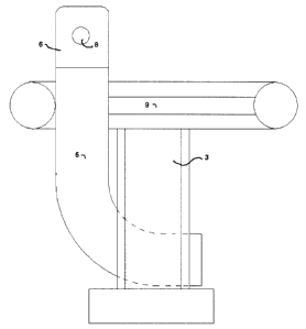
Fig. I is a front elevation of a gate valve with the gate valve lock inserted_

Fig. 2 is a side efevation along line 2-2 of 19g. ? of a gate valve with the
gate valve
lock inserted.

Fig, 3 is a perspective elevation of the gate valve lock alone.
2


CA 02416407 2006-02-02

Fig. 4 is a perspective elevation of the gate valve lock with an altemate type
of
locking device.

DETAILED DESCRIPTION OF THE PREFERRED EMBODIMENT

Fig. I A gate valve I is comprised of a threaded stem 2, a U shaped truss 3
and a
hande 4. A gate valve lock 5, shaped like a"U" as seen from fig I and like an
'L", as
seen from fig. 2 which is a view from line 2-2 of fig. 1, is slipped around
the stern 2
and between the legs of the "U" shaped truss 3 and then rotated upwards so
that a
locking end 6 can pass around one of the arms 9 of the hattdle 4 so that it
lays just
above the handle 4. A locking device 10 is inserted into the locking end 6 to
lock the
gate valve iock S. Once the valve lock 5 is secured, the handle 4 cannot be
moved
appreciably,

Fig. 2 In this side view, the shape of the gate valve lock 5 is clearer as
well as the
way it is inserted between the U shaped truss 3 and one arm 9. Holes S. one
for each
side of the locking end 6, allow for the insertion of the lodtirg device 10.

Fig. 3 This perspective elevation shows the curved l- shape form of the gate
valve
lock 5 with its holes 8 on each side of the locking end S. The lodang end 6 is
preferably but not necessarily narrower than the rest of the gate valve lock 5
to
accomodate the padlock 10 (not shown). Given the various sizes of valves,
different
sizes of gate valve locks S may be required, some too large to accomodate
medium
sized padlocks, therefore the narrowing at the locidrlg end 6 could be useful
in some
cases.

Fig. 4 It should be understood that although a standard padlock is used to
illustrate
the locking device 10 other types of locks can be used inaEuding those that
can be
assembled as part of the gate valve lock 5 such as locking devices commonly
found
to lock post office boxes for example. In such a situation, one of the holes 8
would be
3


CA 02416407 2006-02-02
3a

occupied with the altemate iocldrlg devioe 12 while the other hole g' wotdd be
shaped imegularty in a shape meant to both aii0w and disafiow passage of a
Nocidng
stem14 depending upon Its ocientefion.
Representative Drawing
A single figure which represents the drawing illustrating the invention.
Administrative Status

For a clearer understanding of the status of the application/patent presented on this page, the site Disclaimer , as well as the definitions for Patent , Administrative Status , Maintenance Fee  and Payment History  should be consulted.

Administrative Status

Title Date
Forecasted Issue Date 2007-11-06
(22) Filed 2003-01-20
Examination Requested 2003-01-20
(41) Open to Public Inspection 2004-07-20
(45) Issued 2007-11-06
Deemed Expired 2010-01-20

Abandonment History

There is no abandonment history.

Payment History

Fee Type Anniversary Year Due Date Amount Paid Paid Date
Request for Examination $200.00 2003-01-20
Application Fee $150.00 2003-01-20
Maintenance Fee - Application - New Act 2 2005-01-20 $50.00 2004-11-29
Maintenance Fee - Application - New Act 3 2006-01-20 $50.00 2005-12-14
Maintenance Fee - Application - New Act 4 2007-01-22 $50.00 2006-12-18
Final Fee $150.00 2007-07-25
Maintenance Fee - Patent - New Act 5 2008-01-21 $100.00 2007-12-21
Owners on Record

Note: Records showing the ownership history in alphabetical order.

Current Owners on Record
LACROIX, MAURICE
Past Owners on Record
None
Past Owners that do not appear in the "Owners on Record" listing will appear in other documentation within the application.
Documents

To view selected files, please enter reCAPTCHA code :


To view images, click a link in the Document Description column. To download the documents, select one or more checkboxes in the first column and then click the "Download Selected in PDF format (Zip Archive)" or the "Download Selected as Single PDF" button.

List of published and non-published patent-specific documents on the CPD .

If you have any difficulty accessing content, you can call the Client Service Centre at 1-866-997-1936 or send them an e-mail at CIPO Client Service Centre.


Document
Description 
Date
(yyyy-mm-dd) 
Number of pages   Size of Image (KB) 
Abstract 2003-01-20 1 3
Description 2003-01-20 3 119
Claims 2003-01-20 1 37
Drawings 2003-01-20 3 32
Representative Drawing 2003-03-10 1 4
Cover Page 2004-06-28 1 20
Claims 2006-02-02 1 29
Description 2006-02-02 4 104
Claims 2006-08-08 1 29
Cover Page 2007-10-10 1 21
Correspondence 2007-07-25 1 22
Correspondence 2003-02-19 1 9
Assignment 2003-01-20 2 84
Fees 2004-11-29 1 22
Prosecution-Amendment 2005-08-03 2 49
Fees 2005-12-14 1 22
Prosecution-Amendment 2006-02-02 11 250
Prosecution-Amendment 2006-08-03 1 27
Prosecution-Amendment 2006-08-08 6 154
Fees 2006-12-18 1 23
Fees 2007-12-21 1 22