Note: Descriptions are shown in the official language in which they were submitted.
CA 02416590 2003-02-18
WO 02/32490 PCT/ZA01/00093
1
Title: Improvements in and relating to respiratory apparatus.
SCOPE OF THE INVENTION:
The present invention relates to respiratory apparatus in the form of an
artificial
airway device for placement into the oropharynx of an unconscious patient to
maintain airway patency, to permit attachment to respiratory apparatus, to
permit
either spontaneous or controlled positive pressure ventilation and to prevent
the
inhalation into the lungs of extraneous matter such as vomitus or blood.
THE STATE OF THE ART:
An unconscious patient may have need of some or all four of the above
objectives
for supporting respiration and, therefore, life. During anaesthesia or
resuscitation
this may be achieved by means of an endotracheal tube with an inflatable cuff
around the end which is placed within the trachea, or a laryngeal mask airway
(LMA), which also involves the use of an inflatable cuff at the end of a tube,
the
end of which is placed around the entrance to the larynx and within the
pharynx, or
an oesophageal obstructor airway (EOA) named "Combitube" or derivative. This
2o comprises a double lumen double cuffed tube, the longer tube with attached
cuff
passes into the oesophagus for the purpose of sealing and isolating contents
which
may enter the oesophagus from below or to prevent the escape of gas under
pressure
from above from entering the stomach. The shorter tube for ventilating the
lungs
ends within the pharynx, the oro-nasal outlet from the pharynx being sealed
off
within the pharynx by means of the second cuff which surrounds both tubes,
which
when inflated allows for positive pressure to develop within the pharynx.
Sometimes, an oral or nasal airway tube for preventing obstruction of the
airway is
used in combination with a facemask.
3o Mare recently a cuffed oro-pharyngeal airway (COPA) has been introduced by
Mallinckrodt Medical, Ins, US patent No. 5,713,256, (May 30, 1995) which can
be
used to achieve 3 of the four objectives stated above but fails to protect the
lungs
from extraneous matter that enters the pharynx from entering the lungs. The
Glottis
CA 02416590 2003-02-18
WO 02/32490 PCT/ZA01/00093
2
aperture seal airway of Augustine Medical Inc. PCT publication number: WO
98116273, purports to achieve this advantage, however, it is not as reliable
as was
originally hoped. Numerous other double cuff inflating devices are appearing
in the
current market and may be classed as derivatives of the EOA and COPA above,
e.g.
that of Sato et al US patent No. 5,743,258 (April 28, 1998).
The maximum inflation pressure that can be used before gas leakage occurs
around
the cuffs limits the application of controlled ventilation by the latter two
methods.
They also run the risk of inflating the stomach and do not provide a secure
airway
to from the possible aspiration of vomitus. The LMA provides a partial seal of
the
oesophagus but regurgitation if it gets past the seal is more likely to pass
into the
inflatable bag cavity in the case of the LMA fxom whence the contents are
easily
funneled into the larynx. The COPA does not provide any seal of the
oesophagus.
The Combitube would appear to be an effective device, for controlled
ventilation,
~5 sealing off the oesophagus, but its correct placement can pose problems,
either too
deep or not deep enough. It is also rather elaborate and expensive. The L,MA
would
appear to be ideal except for the fact that the pressures that can be
generated in
controlled ventilation are limited as the mask could be dislodged at higher
inflation
pressures. In addition, although it is partially effective in isolating the
airway from
2o extraneous matter in the pharynx, should any extraneous matter enter the
lumen of
the mask, which does not provide a high quality isolation of the trachea from
pharyngeal matter, it will tend to be funneled into the larynx. To overcome
this
disadvantage an improved LMA named the 'Proseal' LMA incorporates a moderate
bore tube for removing liquid that may accumulate in the mask region of the
airway
25 by suction or siphonage and is disclosed in Japanese Patent No. 2-283378
(Nov.
20.1990). The placement in the trachea of the endotracheal tube is the most
effective
means of achieving all four of the above objectives, however, its use requires
experience, skill and the use of a laryngoscope which in turn has its own
unwanted
side effects consequent upon powerful neural reflex actions. Its placement may
also
3o require the use of muscle relaxing drugs.
It is an objective of the present invention to provide an appropriately shaped
artificial airway which will obviate the need for a cuff blowing up mechanism
for
CA 02416590 2003-02-18
WO 02/32490 PCT/ZA01/00093
3
sealing purposes and yet one that retains most of the advantages of the use of
endotracheal tubes, Combitubes or laryngeal masks in the above mentioned
circumstances and to avoid, as far as it is possible, their individual
disadvantages.
DESCRIPTION:
In accordance with the invention, an artificial airway device of a resilient
material
for use as a combined obturator and airway device without penetration into the
larynx comprises a flexible pre-formed shaped saccular chamber designed to
seal in
1 o the pharynx at the base of the tongue and having a semi-rigid hollow stem
projecting
from a position at or near one end of the chamber at an obtuse angle (i.e.
90° to
180°) to the longitudinal axis of the said chamber. The chamber is
provided with
one or more openings, and is dimensioned and arranged so that in use it is
adapted
to sealingly engage in a patient's pharynx with at least one opening
communicating
with the patient's laryngeal inlet. The stem extends into or through the
patient's
mouth for connection to a breathing circuit.
In order to facilitate the description of the device, the surfaces which are
referred to
herein as 'upper' and 'lower' are those which respectively are upper and lower
2o when the device is in use in a patient lying on his back, or as viewed as a
foot with
its sole lowermost.
The saccular chamber is preferably of a generally rounded foot-shape with the
rounded narrow part of the foot having its under face slightly angled,
preferably
about 15 ° to the longitudinal axis of the chamber, to ease insertion
of the device into
a patient's pharynx. The upper face of the chamber is preferably of a
substantially
concave form and is provided with a transverse ridge with a pair of lateral
lumps to
act as a sealing area which in use is arranged to conform with a patient's
pyriform
fossae and produce a seal with the pharyngeal walls at the base of the tongue.
The
hollow stem forms a flexible junction with the wider part of the foot, which
when
3o flexed does not distort the shape of the sealing portion of the chamber.
The generally foot-shaped saccular chamber may additionally be provided with a
bulb or lobe as a 'heel' extending beyond the stem and so dimensioned and
arranged
CA 02416590 2003-02-18
WO 02/32490 PCT/ZA01/00093
4
so that in use it engages into the patient's nasal-pharynx in order to hold
the device
in the required position,
The relative stiffness of the stem compared with that of the chamber may cause
the
chamber to buckle resiliently at the foot of the stem when the stem is turned
towards
the perpendicular. In use however the design is such that the shape of the
part of the
chamber that would make contact with the pharyngeal wall and the nasal pharynx
is
retained.
The upper face of the chamber between the 'toe' end of the chamber and the
ridge
with the two lumps is preferably concave along its length - or crescent-shaped
in
cross-section in order to better conform with the shape of a patient's
pharynx. This
shape decreases the chance of the toe catching the epiglottis at insertion.
The toe
protrudes beyond the laryngeal opening so that in use it extends into the
entrance of
the oesophagus where it provides a seal in order to prevent any gas from
entering
the stomach.
Two openings are provided on the forward face so that in use they are arranged
to
collect any liquid in the blind end of the chamber and thus in use prevent any
liquid
2o from entering the patient's larynx, trachea or lungs. Liquid can be removed
from
the chamber as required by aspirating it through a catheter inserted into the
chamber.
A vertical ridge between the said two openings may be provided on the upper
face
of the foot so that in use it is arranged to both hold the epiglottis away
from the
opening and will maintain resilience of the ridge between the said two
'lateral
lumps'. The resilience of the ridge is important to prevent the base of the
tongue
moving towards the posterior pharyngeal wall as this movement is associated
with
the epiglottis closing against the laryngeal opening ( or glottis).
The device will now be described in greater detail in relation to its
preferred method
of use. This is a type of pharyngeal outlet obturator airway (POOBAIR) and may
include the standard 15 mm tapered attachment connector inserted into or over
the
CA 02416590 2003-02-18
WO 02/32490 PCT/ZA01/00093
end of the said hollow stem for attachment to breathing apparatus, said stem
extending through the mouth, where it may bend to conform to the gentle curved
shape of the tongue pushing against the hard palate, to the said saccular foot-
shaped
chamber portion that is located in the pharynx, with longitudinal axis
approximately
at right angles to the stem at the entrance to the mouth, the bend at the
junction of
stem with chamber as it hooks into the base of the tongue and expands to form
an
upward-outlet-from-the-pharynx gas tight seal (the said obturator function) in
the
space that extends from the base of the tongue or glossoepiglottic fold and
the two
lateral pyriform fossae or valleculae in the anterior aspect, and in a
crescent shaped
1o arc seals at the same level against the lateral and posterior pharyngeal
walls. The
opening in the front of the chamber corresponds with the laryngeal opening for
the
passage of gas to flow between the larynx and the airway device. The said
saccular
chamber may be extended further and with benefit include each or all of:
a) a rounded extension of the saccular chamber for the purpose of protruding
into
the entrance of the oesophagus to seal the "downward" outlet from the pharynx
into the oesophagus thereby closing off all outlets, obturating downward and
upward outlets from the pharynx except via the chamber and stem open ends of
the device. The blind downward obturating toe of the foot along with the
hollow
chamber also provides a means of collecting secretions within the device.
2o b) an upward extension of the chamber to incorporate a heel-shape that
corresponds
to the nasopharynx and soft palate for the purpose of ensuring a more stable
location of the sealing airway in the pharynx by anchoring the said device in
its
position in the pharynx as it settles into the nasopharynx and soft palate in
such a
way as to prevent expulsion as the airway pressure rises.
Accordingly, one common characteristic in the above existing artificial airway
devices is the need for an inflatable cuff to expand into the right size
pharyngeal
cavity. In devices in accordance with the invention, this is obviated because
they are
supplied in a variety of sizes typically seven, so that the appropriate size
to be
chosen may specifically match the size of each prospective patient's
pharyngeal
cavity.
CA 02416590 2003-02-18
WO 02/32490 PCT/ZA01/00093
6
DESCRIPTION RELATING THE INVENTION MORE SPECIFICALLY TO THE
ENCLOSED NUMBERED DRAWINGS:
The invention will now be specifically described by way of example with
reference
to the accompanying drawings, in which
Figures 1 to 5 show one embodiment of the invention,
Figures 6 to 8 show another embodiment of the invention,
Figures 9 to 11 show another embodiment of the invention and
Figures 12 to 15 show two embodiments adapted to allow for an unusual or
enlarged
pharyngeal tonsillar anatomy.
Fig. 1 is a perspective view of an airway device in accordance with the
invention
from above, Fig. 2 is another perspective view from above, Fig. 3 is a side
elevation , Fig.4 is a front elevation, and Fig. 5 is a sectional side
elevation of the
device in relation to the anatomy of a patient .
Fig. 6 is a sectional side elevation of a second embodiment of the airway
device in
relation to the anatomy of a patient , Fig.7 is a front elevation of the
device in Fig.
6, and Fig.8 is a side elevation. .
Figs. 9 is a perspective view of a 'truncated' form of the device from above,
and
Fig. 10 is a perspective view from the front and Fig. 11 is a side elevation.
Fig. 12 is a side elevation of an alternative form of the device and Fig. 13
is a rear
elevation and Figs. 14 and 15 represent another variant of the same form.
~o
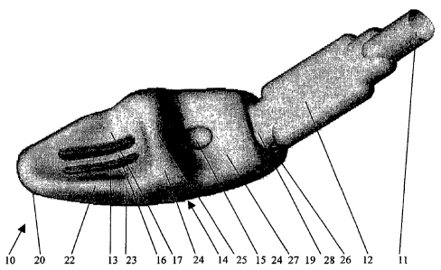
Figures 1 to 5 show an artificial airway device 10 for use as a combined
obturator
and airway device without penetration into the larynx shaped and pre-farmed of
a
resilient material. It comprises a flexible saccular chamber 14 and has a semi-
rigid
CA 02416590 2003-02-18
WO 02/32490 PCT/ZA01/00093
7
hollow stem 12 projecting from a position at or near one end of the chamber 14
with
junction between the stem 12 and the chamber 14 at 19. The stem 12 is set at
about
45° to the longitudinal axis of the chamber 14 and can be flexed into a
curve that
deviates up to 90 degrees from the said longitudinal axis. The chamber has one
or
more openings 13, shown here as two vertical slits.
The device exists in a range of different sizes to fit patients from a child
to a large
adult. In use the anaesthetist will select a suitably dimensioned device,
generally by
measuring the patient's thyroid cartilage and choosing a matching diameter for
the
1o device, so that in use the chamber 14 is adapted to sealingly engage in the
patient's
pharynx with at least one opening 13 communicating with the patient's
laryngeal
inlet. The stem 12 extends into or through the patient's mouth for connection
to a
breathing circuit via an adaptor 40 at its open end 11.
The saccular chamber 14 is of a generally a rounded foot-shape, with the 'toe'
part
of the foot having a lower face 21 slightly angled, preferably about 15
° to the
longitudinal axis of the chamber 14, to ease insertion of the device into a
patient's
pharynx. The chamber is provided with a ridge 25 on its upper face extending
to a
pair of lateral lumps 24 and a substantially convex-planar lower face 30 to
produce a
2o sealing zone so that at this point the shape of the chamber is adapted to
conform
substantially with a patient's pharyngeal walls at the base of the tongue.
The hollow stem 12 forms a flexible junction with chamber at 19, so that when
it is
flexed it does not distort the shape of the sealing portion of the chamber
between the
ridge, the lateral lumps 24 and the rounded under-side of the chamber. The
lumps
24 are adapted to conform with the patient's pyriform fossae to act as an
anchoring
means at the base of the tongue and to keep the base of the tongue from the
posterior pharyngeal wall when in use.
3o The general foot shape is completed (Fig. 1-5) by a bulb or lobe 26
extending
beyond the stem to form a heel. In use (Fig, 5), the lobe 26 is so dimensioned
and
arranged that it engages into the patient's nasal-pharynx in order to hold the
device
in the required position. The relative stiffness of the stem 12 compared with
the
CA 02416590 2003-02-18
WO 02/32490 PCT/ZA01/00093
8
chamber causes the chamber to buckle resiliently at the foot of the stem 19
when the
stem is turned towards the perpendicular to the longitudinal axis of the
chamber,
notwithstanding that in use the shape of the sealing zone around the ridge is
maintained in contact with the pharyngeal wall and the lobe 26 remains engaged
in
the nasal pharynx.
The ridge 25 in the front between the said lateral lumps 24 is sufficiently
resilient so
that in use it holds the epiglottis away from the laryngeal opening. To
increase the
resilience of the chamber 14 and its resistance to collapse at the level of
the said
ridge, 2~ and 25, and thus to facilitate the holding the base of the tongue
away from
the posterior pharyngeal wall, indentations on both surfaces on either side of
the
ridge are provided. In use, these indentations will abut their opposite
numbers 31
with 15 and 32 with 16, to provide the desired stiffness, yet allowing
sufficient
flexibility for the chamber to comfortably adapt to the patient's pharynx and
avoiding subsequent irritation to the throat,
In use as shown in Fig.S The tip of the rounded foot shaped or 'toe' end 20 of
the
chamber is dimensioned so that it protrudes beyond the laryngeal opening
sealing
the oesophagus O in order to prevent gas from entering the stomach.
The two openings 13 in addition to providing the airway connection with the
patient's laryngeal opening are arranged to collect by gravity any liquid in
the
bottom of the chamber l~l and thus in use prevent the liquid from entering the
patient's larynx, trachea or lungs.
A longitudinal bar 16 between the two openings 13 is provided on the upper
face of
the chamber so that in use it is arranged to both hold the epiglottis away
from the
opening and to contribute to the stiffness of the ridge 25 between the two
lumps 24.
Additionally, this helps the ridge to perform one of its main functions,
namely, to
3o keep the base of the tongue away from the posterior pharyngeal wall. The
bar 16
also acts as a barrier to a catheter which may be used to aspirate liquid from
the
chamber during use and prevents it from entering the larynx.
CA 02416590 2003-02-18
WO 02/32490 PCT/ZA01/00093
9
The upper surface of the chamber 14 between the ridge 25 and the stem is in
the
form of a hollow 27. When in position, the hollow 27 receives the posterior
portion
of the tongue with the lumps 24 and the ridge 25 hooked around the base of the
tongue.
The upper face of the toe end of the chamber 14 is provided with a pair of
lateral
ribs 22 with a gentle indentation 23 where they respectively join the lumps
24. This
serves the purpose of the device better conforming to anatomical accuracy,
when in
use, with the said gentle indentation 23 corresponding to pharyngeal mucosa
that
overlies the cricoid cartilage. This is to decrease pressure on the pharyngeal
mucosa
at this site, in order to lower the incidence of sore throats.
The saccular chamber thus fits precisely into the shape of the pharynx and
with the
stem bent to form almost a right angled bend at the junction 19. Airway
pressure
that may rise during positive pressure ventilation would tend to push the
device in
the direction of the nasopharyngeal cavity Nc but is held in position by the
heel 26,
thus preventing it from being dislodged. When it is desirable to remove the
device,
this may be achieved by pulling on the stem 12, which automatically dislodges
26 in
an appropriate direction from the soft palate Sp and nasopharyngeal cavity Nc.
It may also be appreciated that should secretions or stomach contents
accumulate in
the pharynx for any reason, the two openings 13 provide a means for allowing
pharyngeal secretions to flow into the saccular chamber 14 of the hollow
device 10
providing a 'sump' means for the collection of the liquid. This can be
aspirated by
means of a suction catheter that may be passed via the end 11 and stem 12 at a
convenient time.
For quick easy 'blind' (i.e. without the need for a laryngoscope) insertion of
the
device 10, the toe 20 in Figs 3 and 5, is shaped with an anterior curve 21 at
an angle
of about 15° towards the laryngeal opening surface of the toe 20. This
upturned
'toe' 20 facilitates the negotiation of the device 10 at the level of
posterior part of
the tongue and nasopharynx.
CA 02416590 2003-02-18
WO 02/32490 PCT/ZA01/00093
The part of the chamber 14, extending from the ridge 24 to the toe 20 is in
the form
of a concavity with lateral ribs 22, which in cross-section is crescent
shaped. The
purpose is twofold. With insertion, the shape tends to allow for the
epiglottis to
escape being picked up and dragged downwards, producing downfolding and
5 obstruction. The other purpose is that the entrance to the oesophagus is
crescent-
shaped with the anterior to the oesophagus positioned larynx providing the
reason
for the concave aspect of the crescent. As such there is a better downward
seal
without a marked oesophageal dilatation, which tends to cause epiglottic
closure.
1o For quick easy 'blind' (i.e. without the need for a laryngoscope) insertion
of the
device, it may be necessary to use an introduces (a stiff flexible curved rod)
with its
tip inserted into the device from the said first end as far as the toe 20, so
that
possible folding of the device is avoided.
t s In its preferred form, the device is manufactured by means of blow-molding
a grade
of soft thermoplastic with rubbery characteristics and is blow molded into the
shape
described and illustrated in the drawings. The use of suitable resilient
flexible
materials will allow the devices to retain their shape without causing
excessive
pressure against the pharyngeal walls when in position. The device can thus be
2o manufactured at minimal cost and is intended for a single use.
It is desirable that the stem 12 enters the saccular portion 14 at an
appropriate angle
to conform to the shape of the pharynx and outlet via the mouth. In order that
this
be achieved, a measure of flexibility is required and achieved at the junction
19 by
25 means of an oval or rounded rectangular cross-section of the stem 12. In
order to
improve the flexing at the point 19 where the stem meets the chamber, the
cross-
section of the stem is reduced at 28.
As the device 10 is hollow, there is capacity for placement of porous
hydrophobic
30 material or other filter elements within the saccular chamber 1~ to provide
heat and
moisture exchange within the device and filtration,
CA 02416590 2003-02-18
WO 02/32490 PCT/ZA01/00093
11
The device shown in Figs. 6 to 8 is substantially similar to the one shown in
Figs.1
to 5 and described above. It differs to the extent that the stem is joined to
the
chamber 14 just above the ridge 24 so that in use access to the throat and
tonsillar
region is possible.
Alternatively, in Figs 9-11, an artificial airway device 10, for use in place
of an
endotracheal tube to facilitate ventilation of the lung in unconscious
patients, is in
the form of a pharyngeal outlet obturator airway 10 or POOBAIR. It differs
from
the device described in Figs. 1 to 5 in that the toe 20 has been truncated,
and
1 o accordingly does not offer the advantage of being able to provide the
downward seal
to the oesophagus. It offers the one advantage of not requiring such deep
insertion
and therefore is less stimulatory and may be more tolerable at lighter planes
of
anaesthesia.
t s The chamber 14 in use forms an upward-outlet-from-the-pharynx gas tight
seal at
the zone 24,25 in the space that extends from the base of the tongue or
glossoepiglottic fold GE and the two pyriform fossae in the anterior aspect
that
correspond with the two lumps 24, the lateral and posterior pharyngeal walls
and
extending to the toe 20 of the chamber 14 that corresponds to the nasopharynx
N
2o and soft palate S.
The two embodiments of the device as shown in Figs 12 and 13, and 14 and 15
have
a narrowed neck 42 between the body of the saccular chamber 14 and the heel
26.
As shown in Fig. l2- 15 the advantage of the heel 26 is retained which is
adapted to
25 engage in the nasal pharynx. The advantage of these embodiments is that
they can
be used in cases where the patient's tonsillar anatomy would preclude the use
of the
devices described above. They can also provide improved flexibility and
simplify
mould making.
CA 02416590 2003-02-18
WO 02/32490 PCT/ZA01/00093
12
KEY TO ANATOMICAL TERMS
Ao = Anterior Oesophageal
Wall
B = Base of Tongue
Ep Epiglottis
=
Ge = Glosso-epiglattic
fold
Hp = Hard palate
L = Laryngeal opening
M = Mouth
1 o Nasal cavity
Nc
=
N = Nasopharynx
O = Oesophagus
Oc = Oral cavity
P = Pharynx
Sp Soft palate
=
Te = Teeth
T = Tongue
Tr = Trachea
U = Uvula