Note: Descriptions are shown in the official language in which they were submitted.
CA 02416649 2003-O1-24
WO 02/07609 PCT/USO1/41419
APPARATUS AND METHOD FOR REPAIRING OR REATTACHING
SOFT TISSUE
FIELD OF THE INVENTION
The present invention relates generally to surgical devices and procedures
and,
more particularly, to an apparatus and method for suturing or repairing soft
tissue
injuries such as, for example, tears in the meniscus of the knee.
BACKGROUND OF THE INVENTION
The meniscus is the intra-articular cartilage found ll1 the joint that
separates
the femur from the tibia, that is, the knee joint. Proper functioning of the
knee joint
depends, in part, upon the meniscus' ability to provide the joint with
biomechanicah
stability and shock absorption during ambulation. Frequently, the meniscus is
injured
or torn, causing joint instability, pain in the knee, and resultant
difficulties in
ambulation. Two common surgical techniques are used in an effort to alleviate
the
pain associated with this type of injury. The first of these techniques is
referred to as
a menisectomy, which is the removal of the piece of tissue that has torn away
from
the greater meniscus. Depending upon the severity of the tear ili the meniscal
tissue,
the surgeon may regard this as the best surgical option for the patient. The
second
technique involves the installation of a surgical implant into the segments of
torn
meniscal tissue to promote the fusion of the tissue and facilitate normal
healing of the
injury. In many cases, the surgeon will regard this latter option as more
desirable than
the former, since it is far less radical and potentially has fewer
degenerative
consequences, such as the development of osteoarthritis, for the patient over
time.
Presently known devices and methods for delivering a surgical suture or
suture-like implant into the meniscus or other soft tissue for repairing a
tear in that
tissue are unsatisfactory in several regards. Specifically, the prior art
devices and
methods may frequently prolong otherwise elegant surgical procedures by
imparting
the procedure with unnecessary mechanical inefficiencies. For example, the
inability
of prior an devices to pass suture or implant material into and out of soft
tissue
through the same body portal necessitates that a plurality of incisions be
made into a
patient's body, thereby increasing the level of trauma experienced by the
patient
CA 02416649 2003-O1-24
WO 02/07609 PCT/USO1/41419
during the procedure. Additionally, prior at~t rotating suture or implant
feeding
mechanisms employ counterintuitive methods of operation that require the
surgeon to
rotate the wheel mechanism in a direction that is opposite the direction in
which the
surgeon desires to feed the suture or implant material. Moreover, currently
known
devices are incapable of accommodating variably dimensioned suture or implant
materials, thereby presenting the surgeon with two equally undesirable
options: First,
the surgeon must use a single suture or implant material having a particular
diameter
or thickness, regardless of the needs of the patient; or, second, the surgeon
must
employ a plurality of surgical instruments, each capable of accommodating
particularly dimensioned suture or implant material, which necessarily
increases the
number of steps required to complete the procedure and likely prolongs its
duration.
In view of the foregoing, a need exists for an improved apparatus and method
for
repairing an injury to soft tissue, which overcomes the shortcomings of the
prior art.
Thus, there is a need for an apparatus and method, which enable a surgeon to
pass a suture, or other generally elongated implant material into and out of
injured,
torn, or detached soft tissue in essentially the same direction. There is also
a need,
especially in the case of arthroscopic surgeries, for an apparatus and method
which
are capable of passing a suture or implant material into and out of a joint
space
through a single body portal, thereby reducing the number of incisions
required to
accomplish the procedure. There is also a need for a single apparatus, which
is
capable of delivering sutures or implant materials of various diameters or
thiclcnesses.
There is also a need for an apparatus having a rotating suture or implant
feeding
mechanism that permits the surgeon to rotate the feed mechanism in the same
direction that the surgeon desires the suture or implant material to be fed.
There is
also a need for an apparatus capable of passing a plurality of tissue-piercing
device6
and suture legs through soft tissue at one time. There is also a need for an
apparatus,
which can selectively orient the suture or implant material W either a
horizontal,
vertical, or diagonal direction, depending upon the needs of the patient
and/or the
desires of the surgeon. There is also a need for an apparatus and method for
passing a
suture or implant through soft tissue and grasping the end of the suture or
implant on
the opposite side of the soft tissue. Additionally, there is a need for an
apparatus and
2
CA 02416649 2003-O1-24
WO 02/07609 PCT/USO1/41419
method for passing a needle through a body portal and to the site of soft
tissue injury
while also protecting the surrounding tissue and nerves from damage that can
be
caused by the passage of that needle.
SUMMARY OF THE INVENTION
The present invention is an apparatus and method for delivering or iilstalling
a
surgical suture or suture-like implant into soft tissue, such as the meniscus
of the knee
for example, for the reattachment or repair of that tissue. The apparatus and
method
of the invention facilitate ease of placement of the suture or implant by the
surgeon,
protect the surrounding tissue and nerves from damage during its use, and
permit all
suturing to occur through a single body portal. The present invention can be
used in
either open or arthroscopic surgical procedures and can be used for any tears
in the
meniscus or for other injuries to soft tissue, which require a suture or
implant to be
passed through the tissue to facilitate reapproximation and healing of that
tissue. In
accordance with the invention, an injury to soft tissue; such as a tear in the
meniscus
of the knee joint or detachment of soft tissue fiom bone, is repaired through
a single
body portal by installing a surgical suture across the injury, tear, or
detachment and
passing that suture back through the body poual so that the suture can be j
oined and
the injury, tear, or detachment can be reapproximated by the surgeon while
working
through the single body portal. It should be understood that the device of the
iilstant
invention can be used to pass suture or suture-like implants equally
effectively. Thus,
wherever the terms "implant" or "implant material" are used herein, it should
be
understood that the principles of the present invention apply equally to'the
use of all
manner of surgical suture or suture-like materials.
The apparatus of the instant invention includes a guide structure, which can
be
inserted through a body portal and brought iilto proximity with particular
soft tissue.
The guide structure is suitably configured to guide a length of suture or
surgical
implant material through the soft tissue and to bring legs of the length of
implant
material into proximity with each other. The guide structure includes a
suitable,
selectively moveable, tissue-piercing device, such as a needle for example,
capable of
piercing soft tissue and of being withdrawn from the soft tissue so that
suitable suture
3
CA 02416649 2003-O1-24
WO 02/07609 PCT/USO1/41419
or implant material then can be fed through the guide structure and into the
soft tissue.
The guide structure fiu-ther is configured to be withdrawn toward the body
portal and
from the body in a manner which causes the guide structure to become
disengaged
from the length of implant material while leaving the length of implant
material
extending through the soft tissue and the legs of the length of implant
material in
proximity with each other. This then permits the surgeon, at his or her
discretion, to
join the approximated portions of implant material to accomplish the repair or
reattachment of the soft tissue. However, it should be understood that the
present
invention does not require that the portions of the length of implant material
be
joined, nor is the present invention limited or restricted in any way to the
joining of
these portions of implant material.
In an exemplary.embodiment of the iilstant invention, the guide structure
further includes a pair of guide portions supported in spaced apart relation
to each
other and defining a gap which enables soft tissue to be disposed between the
guide
portions; a tissue-piercing device moveable in the gap between the guide
portions and
configured to pierce soft tissue disposed in the gap between the guide
portions; and an
introduces moveable in opposite directions in the gap between the guide
portions.
The introduces is moveable in one direction to form a passageway in the gap
for
guiding a length of implant material through soft tissue disposed within the
gap and
also is moveable in an opposite direction for re-establishing the gap between
the guide
portions. Thus, the gap that has been re-established between the guide
portions
enables the legs of the length of implant material to pass through the gap as
the guide
structure is withdrawn toward the body portal. The guide portions are suitably
configured to guide the legs of the length of implant material into proximity
with each
other as the guide structure is withdrawn from the surgical site and toward
the body
portal.
In another exemplary embodiment of the present invention, the apparatus
further includes a selectively engageable force applying device for feeding
the suture
or implant material fiom the proximal end of the guide structure to the distal
end of
the guide structure. The force applying device feeds suture or implant
material
through the guide structure by selectively engaging a length of implant
material and
4
CA 02416649 2003-O1-24
WO 02/07609 PCT/USO1/41419
thereby driving the length of implant material through the guide structure.
'The force
applying device can also selectively disengage from the length of implant
material to
enable the length of implant material to slide more freely within the guide
structure,
as when the guide structure becomes disengaged from the length of implant
material
and is withdrawn from the body portal for example.
Other objects, features, and advantages of the present invention will become
apparent to those skilled ll1 the art from the following detailed description.
It should
be understood, however, that the detailed description and specific examples,
while
indicating exemplary embodiments of the present invention, are given for
purposes of
illustration only and not of limitation. Many changes and modifications within
the
scope of the instant invention may be made without departing fiom the spirit
thereof,
and the invention includes all such modifications.
BRIEF DESCRIPTION OF THE DRAWINGS
The features and advantages of the instant invention reside in the details of
construction and operation as more fully depicted, described, and claimed
hereinafter;
reference being had to the accompanying drawings forming a part hereof,
wherein
like numerals refer to like parts throughout and wherein:
FIG.1 is a side view of an exemplary embodiment illustrating the major
components of the device;
FIG. 2 illustrates the tissue-piercing device of the embodiment of FIG. 1;
FIG. 3 illustrates the introduces tube of the device of FIG. 1, including an
implant feeding mechanism and an introduces tube handle having a threaded
member
for attaching the introduces tube handle to the guide structure handle of FIG.
4;
FIG. 4 illustrates the assembly of the guide structure, including the guide
tubes and the guide tube handle, wherein the guide tube handle has a female
threaded
portion adapted to attach the introduces tube handle of FIG. 3;
FIGS. 5-14 illustrate a method of using the embodiment of FIG. 1 to repair a
torn meniscus;
CA 02416649 2003-O1-24
WO 02/07609 PCT/USO1/41419
FIG.15 illustrates the guide tubes of another exemplary embodiment of the
device having a plurality of introducer tubes and guide tubes which enable a
plurality
of tissue-piercing devices to pass through torn tissue simultaneously;
FIG. 16 is a detailed view of the device of FIG. 15 illustratiilg the distal
end of
the device and cross sectional views of the guide tubes;
FIGS. 17-23 illustrate a method of using the device of FIGS. 15 and 16,
wherein a plurality of tissue-piercing devices cam be passed through torn
tissue
simultaneously;
FIG. 24 is a detailed cross sectional view of the feeding mechanism located on
the introducer tube handle of FIG. 3;
FIG. 24A is a top view of the feeding mechanism of FIG. 24;
FIG. 25 illustrates another exemplary embodiment of the implant feeding
mechanism located on the introducer tube handle;
FIGS. 26 and 26A illustrate exemplary embodiments of the device having
alternative orientations or bends in the guide structure, which facilitate
manipulation
of the device around anatomical structures of the body;
FIG. 26B is an isometric view of the device of FIG. 4 defmiilg the directions
referred to herein;
FIGS. 27, 27A, 27B, 27C, and 27D illustrate another exemplary embodiment
of the device, wherein a receiver has a plurality of moveable elements for
receiving
and retaining a length of implant material guided through segments of torn
soft tissue;
FIGS. 28, 28A, and 28B illustrate another exemplary embodiment, wherein a
tissue-piercing device connected to a length of implant material is retained
by a
receiver formed by a plurality of flexible biased members;
FIG. 29 illustrates yet another embodiment of the device, wherein a plurality
of tissue-piercing devices can pierce segments of torn tissue and allow a
length of
implant material to pass from a guide tube set, through segments of torn
tissue,
6
CA 02416649 2003-O1-24
WO 02/07609 PCT/USO1/41419
through a channel device, back through the tissue, and then into another guide
tube
set, in a maimer which delivers a vertical stitch through the segments of torn
tissue;
FIGS. 30 and 30A illustrate yet another embodiment of the device which
allows a plurality of tissue-piercing devices to pass through segments of torn
tissue
and permits a length of implant material to pass through the torn tissue
twice, in a
manner which delivers a horizontal stitch through the segments of tom tissue;
FIG. 31 illustrates an exemplary embodiment of the device superimposed on a
top cross-sectional view of a meniscal tear; and
FIG. 32 is a diagram depicting a lateral view of the knee and illustrating the
use of the exemplary embodiment of the device shown in FIG. 1 to repair the
meniscus.
DETAILED DESCRIPTION
The present invention is an apparatus and method for delivering-or installing
a
surgical suture or suture-Iike implant material iilto soft tissue, such as the
meniscus of
the knee for example, for the reapproximation or reattachment of that tissue.
The
device is pauticularly useful for repairing tom or detached intra-anticular
tissue, such
as the meniscal cartilage of the knee joint, and can be used in either open or
arthroscopic surgical procedures. It should be understood that the instant
invention is
not limited to the use of surgical suture. The present invention includes the
use of
other implants or implant materials, as now known in the art or may be
designed in
the future, which may have similar physical or chemical properties to surgical
suture
but are better able to promote fixation and healing of soft tissue. Wherever
the terms
"implant" or "implant materials" are used herein, it should be understood that
these
terms mean all manner of surgical suture or suture-like materials, including,
without
limitation or restriction, nonbioabsorbable or bioabsorbable materials,
further
includiizg allograft, autograft, or xenograft materials.
FIGS. 1 through 4 illustrates the major components of an exemplary
embodiment of the device of the instant invention. FIG. 1 is a side view of
the device
100, which generally illustrates the manner in which the various components
are
7
CA 02416649 2003-O1-24
WO 02/07609 PCT/USO1/41419
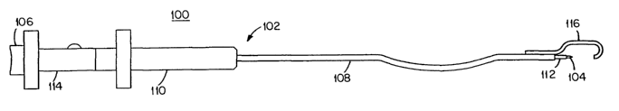
related to each other when the device 100 is in use. The device 100 comprises
a guide
structure 102, which fiu~ther comprises a tissue-piercing device 104, a tissue-
piercing
device handle 106, a pair of guide portions 108 and 116, a guide structure
handle 110,
an introduces 112, and an introduces handle 114.
FIG. 2 better illustrates the tissue-piercing device 104 of FIG. 1. The tissue-
piercing device 104 can be any suitable structure for piercing the soft tissue
(not
shown) through which a surgeon intends to pass suture or implant material (not
shown). The tissue-piercing device 104 can be, for example, a needle or other
suitable fme gauged structure. Preferably, the tissue-piercing device 104 is
formed at
the distal end of an elongated cylindrical rod or shaft 118 which preferably
can slide
in opposite directions within the introduces 112. The shaft 118 preferably is
configured to enable the tissue-piercing device 104 to move in one direction
within a
gap between the guide portions 108 and 116 to pierce soft tissue and to move
in an
opposite direction for withdrawing the tissue-piercing device 104 from the
introduces
112, so that a length of implant material can be inserted into and moved
within and
through the introduces 112. Shaft 118 preferably has an outer diameter that is
similar
to that of the suture or suture-like material, which the surgeon intends to
pass through
the injured or torn tissue. The suture or suture-like material may be of any
suitable
thickness or diameter but preferably has a diameter ranging fiom about 0.008
inches
to about 0.030 inches. The distal tip 120 of the tissue-piercing device 104
preferably
has a relatively sharp point and a generally conical shape that preferably is
similar to
that of a sewing needle or a pin to facilitate the piercing of the injured
soft tissue by
the tissue-piercing device 104. The tissue-piercing device 104 preferably has
a handle
106 permanently axed to its proximal end 122, thereby enabling the surgeon to
control the tissue-piercing device 104 with minimal damage to the surgeon's
surgical
glove (not shown). The needle or tissue-piercing device 104 preferably is
moveable
in opposite directions within the introduces 112 and the guide portions 108
and 116,
such that the needle or tissue-piercing device 104 is moveable in one
direction for
piercing the segments of torn tissue and iii another direction for withdrawing
the
needle or tissue-piercing device 104 from the segments of toi~i tissue to
enable a
length of implant material to be guided through the segments of torn tissue.
8
CA 02416649 2003-O1-24
WO 02/07609 PCT/USO1/41419
FIG. 3 better illustrates the introduces 112 of FIG. 1. In one embodiment, the
introduces 112 is preferably an elongated cylindrical tube 124 having an
internal
diameter that is preferably similar to that of the outer diameter of the
tissue-piercing
device 104 of FIG. 2. The introduces tube 112 may have any suitably configured
distal end poution, but preferably has a conical or chamfered distal end
portion 126
capable of following the tissue-piercing device 104 through soft tissue. In
this
manner, the introduces tube 112 can pass through injured soft tissue when the
introduces tube 112 is placed concentrically over the tissue-piercing device
104 of
FIG. 2. This configuration further permits the introduces tube 112 to extend
at least
partially into the guide portion 116 of FIG. 4 to form, at least temporarily,
a
passageway extending substantially between the introduces tube 112 and the
guide
portion 116 for guiding a length of implant material through the torn tissue.
The
introduces tube 112 also preferably has an introduces tube handle 114 rigidly
attached
to its proximal end 128, which handle 114 preferably has a suitable fastener
means,
such as threaded member 130, for attaching the introduces tube handle 114 to a
suitable corresponding fastener means, such as a corresponding female threaded
portion 132, shown on guide structure handle 110 in FIG. 4, for attaching the
proximal end 134 of the guide structure handle 110 to the introduces tube
handle 114.
The introduces tube 112 preferably is configured to receive and guide a length
of
implant material, and the introduces tube handle 114 preferably comprises a
force
applying device, such as feeding mechanism 138. Feeding mechanism 138 is
preferably configured to apply a suitable amount of directional force to a
length of
implant material disposed within the introduces tube 112 to move the length of
implant material within and through the introduces tube 112. Thus, feeding
mechanism 138 provides a surgeon with means for advancing a suture or suture-
like
material from the proximal end of the device 100, shown in FIG. 1, to the
distal end of
the device 100 when the tissue-piercing device 104 preferably has been
withdrawn
from the device 100 after the segments of torn tissue have been suitably
pierced. In
addition, the feeding mechanism 138 provides the surgeon with suitable means
for
retracting or reversing the direction of the suture or implant matexial from
the distal
end to the proximal end of the guide structure 102 of FIG. 1. The feeding
mechanism
138 is described in greater detail below with reference being had to FIGS. 24,
24A,
9
CA 02416649 2003-O1-24
WO 02/07609 PCT/USO1/41419
and 25.
FIG. 4 better illustrates the assembly of the guide structure 102 of FIG. 1.
Preferably, guide structure 102 is configured to be at least partially located
within an
articular space, such as a knee joint, to facilitate installation of an
implant in soft
tissue, such as the meniscus, located within that ai-ticular space.
Preferably, the guide
structure 102 comprises a pair of guide portions 108 and 116, which are
preferably a
pair of guide tubes 108 and 116. Each guide tube 108 and 116 preferably is
disposed
in a common plane, which has a thickness equal to the largest outer diameter
of the
pair of guide tubes 108 and 116. Preferably, a gap is formed between the guide
tubes
108 and 116, which gap also is located within this common plane. The
introduces
tube 112 of FIG. 3 and the tissue-piercing device 104 of FIG. 2 also are
moveable
within this common plane and preferably are configured to enable a length of
implant
material to be moved within the common plane. Preferably, the thiclcness of
the
common plane is dimensioned to enable the pair of guide tubes 108 and 116 to
be at
least partially located within an articular space, such as a knee joint (not
shown).
As further illustrated in FIG. 4, each of the guide tubes 108 and 116
preferably
comprises an elongated cyliuldrical tube having an internal diameter similar
to that of
the outer diameter of the introduces tube 112 of FIG. 3. In one embodiment,
the guide
tube 108 preferably has at least one bend 140, which enables the device 100 of
FIG. 1
to be manipulated or maneuvered around anatomical structures, such as bones,
and
other anatomical features that may hinder or prevent straight or axial passage
of the
device 100 through the body of a patient. In this embodiment, the introduces
tube
112, S110Wn ll1 FIG. 3, preferably is of suitable flexibility to permit the
introduces tube
112 to move lengthwise through the at least one bend in the guide tube 108
and/or
through any bends in the guide tube 116, as required. In one-embodiment, guide
tube
116 preferably is attached or fixed to the guide tube 108. The guide tube 116
is
preferably an elongated cylindrical tube, which preferably is bent in such a
manner
that its distal end 142 is generally facing the distal end 144 of the guide
tube 108.
Preferably, the guide tube 116 also has one or more bends which pei~nit
facilitated
manipulation or extension of the device around anatomical structures or masses
of the
body. The guide tube 116 preferably is attached rigidly to the outer diameter
of the
CA 02416649 2003-O1-24
WO 02/07609 PCT/USO1/41419
guide tube 108 so that the proximal end of the guide tube 116 generally faces
the
same direction as the proximal end of the guide tube 108. Preferably, the
distal ends
142 and 144 of the guide tube 116 and the guide tube 108, respectively, have
openings which are spaced apart and aligned with each other to allow flee
movement
or passage of the tissue-piercing device 104 of FIG. 2, the introducer tube
112 of FIG.
3, and suture or suture-like material through the guide tube 108 and the guide
tube
116. The proximal end 134 of the guide structure 102 preferably is attached
rigidly to
a guide structure handle 110. As noted above with respect to FIG. 3, the guide
structure handle 110 preferably includes a fastener means, such as a female
threaded
portion 132, located on the proximal end 134 of the guide structure handle 110
for
matingly and engagingly attaching a suitable corresponding fastener means,
such as
threaded member 130, on the introducer tube handle 114, shown in FIG. 3.
FIGS. 5 through 14 describe the general method of using the device 100 of
FIG. 1. Generally, a method for installing an implant in soft tissue comprises
the
steps of providing a guide structure, locating the guide structure in a
selected
orientation with respect to the soft tissue, operating the guide structure to
guide a
length of implant material through the soft tissue, and withcliawing the guide
structure
from the soft tissue in a manner which maintains the implant material iii the
soft tissue
and disengages the guide structure from the length of implant material with
the legs of
the length of implant material ill proximity to each other. In a preferred
embodiment,
the method for installing an implant in soft tissue further comprises the step
of
manipulating the guide structure into a selected orientation after the length
of implant
material has been guided through the soft tissue. Preferably, the selected
orientation
enables the friction between the length of implant material and the soft
tissue to cause
the guide structure to disengage from the length of implant material as the
guide
structure is withdrawn from the soft tissue.
FIG. 5 illustrates the first step of a preferred method for installing an
implant
in soft tissue in accordance with the principles of the present invention. It
should be
understood that while the method of the present invention is exemplified with
reference to the repair of a meniscal tear, the principles of the instant
invention are
applicable to the repair and/or reattachment of a variety of soft tissues and
are not
11
CA 02416649 2003-O1-24
WO 02/07609 PCT/USO1/41419
intended to be limited to the repair of meniscal tissue. FIG. 5 shows a cross
sectional
view of the posterior horn of the meniscus 146 placed between the distal end
144 of
the guide tube 108 and the distal end 142 of the guide tube 116. In the
illustrated
example, the proximal end of the device 100 preferably is inserted
concentrically
through a portal (not shown) located in a generally anterior aspect of the
knee (not
shown). The distal end 142 of guide tube 116 is placed on the posterior aspect
of the
meniscus and is aligned with the tear that is to be repaired, as better seen
in FIG. 31.
Preferably, the distal end 144 of guide tube 108 is directed toward the torn
segment of
the meniscus 148 so that the implant material (not shown) preferably passes
directly
through the two segments 148 and 146, respectively, of the meniscus.
Referring next to FIG. 6, after the device is placed in the desired location
over
the meniscus, the tissue-piercing device 104 and the introduces tube 112
preferably
are slid concentrically through the guide tube 108 until the distal tip 120 of
the tissue-
piercing device 104 contacts the torn meniscal tissue 148. The distal end 126
of the
introduces tube 112 preferably trails or follows immediately behind the
conical distal
tip 120 of the tissue-piercing device 104 as the tissue-pierciilg device 104
passes
through the soft tissue, thereby reducing potential entrapment of the
introduces tube
112 within the meniscal tissue.
Turning next to FIG. 7, the tissue-piercing device 104 and introduces tube 112
preferably are then forced through the torn segment of meniscal tissue 148 and
the
intact meniscal hom tissue 146 until the distal tip 120 of the tissue-piercing
device
104 preferably passes the distal end 142 of the guide tube 116 and advances no
fuuther. As illustrated in FIG. 8, the introduces tube 112 preferably is
advanced until
contact is made with the distal end 142 of the guide tube 116. The tissue-
piercing
device 104 preferably is then retracted from the device 100 in the direction
indicated
by the arrow shown in FIG. 7.
Preferably, as illustrated in FIGS. 9 and 10, once the introduces tube 112 and
the guide tube 116 are proximate each other at junction or passageway 150, and
the
tissue-piercing device 104 has been retracted as shown in FIG. 8, a clear path
is
established through the passageway 150, which permits a suitable length of
suture,
12
CA 02416649 2003-O1-24
WO 02/07609 PCT/USO1/41419
suture-like material, or similar implant material 152 to be fed or passed
through the
passageway 150 and into the guide tube 116 to deliver an implant or stitch
through the
tone segments of meniscal tissue 148 and 146. Preferably, this suture or
implant 152
is delivered by the feeding mechanism 138, as shown in FIG. 1 and described in
greater detail below with reference being had to FIGS. 22A, 22B, and 23.
Once the desired length of suture or implant has been passed through the soft
tissue, the introducer tube 112 preferably is retracted toward the body portal
iii the
direction illustrated by the arrow shown in FIG. 11. Preferably, as
illustrated in FIG.
12, the guide structure 102 then is manipulated into a selected orientation,
such as
being turned 90 degrees for example, within the joint space. As better seen in
FIG.
13, this selective manipulation and orientation of the guide structure 102
preferably
allow the guide structure 102 to utilize the friction created between the
length of
implant material 152 and the segments of torn tissue 148 and 146 to disengage
the
length of implant material 152 from the guide structure 102 as the guide
structure 102
is retracted toward the single body portal (not shown) in the direction
indicated by the
arrow shown in FIG. 13. As illustrated in FIG. 14, this method of retracting
the guide
structure 102 ensures that the implant material 152 remains stitched through
the two
segments of meniscal tissue 148 and 146, permitting the two legs or end
portions
154a-b of the suture or implant material 152 to be connected in a manner that
facilitates the fusion and healing of the segments of meniscal tissue 148 and
146. It
should be noted that the particular method of connecting the legs or end
portions
154a-b of implant material 152 is beyond the scope of the present-invention.
FIGS. 15 and 16 illustrate an exemplary embodiment of the device 200 of the
instant invention. The device 200 preferably includes a pair of guide portions
comprising a pair of guide tube sets 208 and 216, each of which further
comprises a
pair of adjacent guide tubes 209 and 203, respectively. Preferably, the guide
tube sets
208 and 216 are configured to enable portions of a length of implant material
to be
guided through soft tissue. Preferably, at least one of the pair of guide
portions, such
as guide tube set 216, is further configured to maintain the legs of the
portions of
implant material in adjacent spaced relation to each other as the portions of
implant
material are guided through the soft tissue. The configuration of the guide
tube sets
13
CA 02416649 2003-O1-24
WO 02/07609 PCT/USO1/41419
208 and 218 preferably permit a plurality of tissue-piercing devices and a
plurality
sutures or implants, or suture or implant legs, to pass through the torn
tissue
simultaneously.
FIG. 16 is a detailed view of the distal end of the device 200 shown in FIG.
15. This embodiment preferably is used in a different manner than the
embodiment
illustrated in FIG. 1 in that the suture or implant material is fed from the
guide tube
set 216 to the guide tube set 208, rather than from the guide tube 108 to the
guide tube
116 as described above with reference to FIGS. 9 and 10. In this embodiment,
as seen
iii cross sectional view 201, at least one of the pair of guide portions, such
as the
guide tube set 216, preferably comprises a single lumen tube structure
defining a pair
of adjacent guide tube portions 203 having a reduced central portion 205
joining the
pair of adjacent guide tube portions 203. Each of the pair of adjacent guide
tube
portions 203 is configured to guide a leg or portion of a length of implant
material
(not shown) in a lengthwise direction, and the central portion 205 is
configured to
maintain the pair of adjacent guide tube portions 203 in spaced relation to
each other,
thereby allowing a connecting portion of the length of implant material to
slide
sideways through the central portion 205 with an interference fit. Thus,
preferably a
plurality of legs or portions of a length of suture or implant material can be
simultaneously fed into the guide tube set 216 and through torn tissue in a
spaced
apart mariner. The cross sectional view 207 of the guide tube set 208
illustrates a
preferred double lumen structure having adjacent guide tubes 209 through which
legs
or portions of implant material can pass subsequent to passing through the
guide tubes
216 and the torn soft tissue.
FIGS. 17 through 23 illustrate an exemplary method of using the device 200
shown in FIG. 15. The method of using this embodiment is a modified version of
the
method described above with reference to FIGS. 5 through 14. As illustrated in
FIG.
17, the device preferably is placed over the meniscus with the distal end 242
of the
guide tube set 216 contacting the posterior aspect of the meniscus 246 and the
distal
ends 244 of the guide tube set 208 generally directed toward the torn piece of
meniscal tissue 248. As better seen in FIG. 18, the tissue-piercing devices
204
preferably perform a similar function and are used in an identical manner to
that
14
CA 02416649 2003-O1-24
WO 02/07609 PCT/USO1/41419
described above with reference to FIGS. 5 through 14.
FIG. 19 illustrates a plurality of iiitroducer tubes 212 concentrically
inserted
within the guide tube set 208 and fully extended toward the distal end 242 of
guide
tube set 216. The method of passing the introduces tubes 212 through the
segments of
torn tissue is as described above with reference to FIGS. 6 through 8,
notwithstanding
the difference of using a plurality of introduces tubes 212 and a plurality of
tissue-
piercing devices 204, as shown in FIG. 18. In a manner similar to that
described
above with reference to FIGS. 8 through 10, the method of using the embodiment
of
FIG. 15 preferably places the introduces tubes 212 and the guide tube set 216
proximate each other at a junction or passageway 250. Thus, after the tissue-
piercing
devices preferably have been retracted in a manner similar to that described
above
with reference to FIG. 8, a clear path is established through the passageway
250,
which permits a plurality of legs or portions of a suitable length of suture,
suture-like
material, or similar implant material to be fed or passed through the guide
tube set
216, through the passageway 250, and then into the introduces tubes 212,
effectively
delivering a suture or stitch through torn segments of meniscal tissue.
FIG. 20 illustrates a suture or implant 252, having a connecting portion 211
and legs or end portions 254a-b, being advanced, _ as indicated by the arrows,
through
the guide tube set 216, through the segments of meniscal tissue 246 and 248,
and into
the introduces tubes 212 within the guide tube set 208. Preferably, as the
suture or
implant 252 continues to be advanced by a surgeon pulling on the end portions
254a-
b, the loop or connecting portion 211 eventually contacts the proximal ends
213 of the
guide tube set 216 and has an interference fit within the guide tube set 216.
As
illustrated in FIG. 21, as the suture or implant 252 is advanced further, the
loop 211
eventually clears the distal end 242 of the guide tube set 216 and contacts
the
posterior aspect of the meniscal horn tissue 248. Then, as seen in FIG. 22,
the guide
structure 202 preferably is selectively oriented, or turned, and retracted
toward the
body portal, as described above in greater detail with reference to FIGS. 12
through
14. In this manner, a complete stitch of the implant material 252 is delivered
through
the two segments of torn meniscal tissue with a loop 211 on the posterior
aspect of the
meniscus 248. As illustrated in FIG. 23, the plurality of legs or end portions
254a-b
CA 02416649 2003-O1-24
WO 02/07609 PCT/USO1/41419
of implant material 252 are then positioned so that they easily may be
connected to
facilitate the fusion and healing of the segments of meniscal tissue 248 and
246.
Figures 24A and 24B are detailed views of an exemplary embodiment of the
inventive suture or implant feeding mechanism 138, as shown in FIG. 1. The
feeding
mechanism 138 is a force applying device, which preferably includes a drive
wheel
131 extending at least partially into the handle 114 and the introduces tube
112.
Preferably, the drive wheel 131 is rotatable about an axis or axle 137 and has
an
external surface suitably configured for applying force to and moving a length
of
implant material 152 through the introduces tube 112 of FIG. 1. The drive
wheel 131
preferably has an outer diameter 133 and an inner diameter 135, wherein the
inner
diameter 135 is larger than the outer diameter of the axle 137. The suture
guide 139
within the introduces tube handle 114 has a proximal suture introducing end
141 and a
distal suture-receiving end 143. In accordance with one embodiment of the
invention,
the axle 137 and the drive wheel 131 are both selectively moveable in one
direction
transverse to the length of implant material 152 within the introduces tube
112 to
engage and move or drive the length of implant material and are moveable in an
opposite direction to disengage from the length of implant material to allow
the length
of implant material to slide within the introduces tube 112. In another
embodiment,
the drive wheel 131 is selectively moveable relative to the axle 137 in one
direction
transverse to the length of implant material 152 within the introduces tube
112 to
engage and move or drive the length of implant material and is moveable in an
opposite direction to disengage from the length of implant material to allow
the length
of implant material to slide within the introduces tube 112. In both of these
embodiments, a surgeon is thereby permitted to depress and rotate the drive
wheel
131 to move the length of implant material 152 through the introduces tub 112
by
frictionally engaging the implant material 152 with the drive wheel 131. W
this
manner, a surgeon also can selectively utilize implant materials 152 of
varying
thiclcnesses or diameters with a single device, rather than requiring a
particular device
for each of the desired suture or implant diameters, since the feeding
mechanism 138
preferably permits selective depression of the drive wheel 131, as required by
the
diameter or thickness of the employed implant material 152. As illustrated in
the top
16
CA 02416649 2003-O1-24
WO 02/07609 PCT/USO1/41419
view of FIG. 24A, the outer diameter 133 of the drive wheel 131 preferably has
a
suitably configured surface, such as teeth or serrations 145, for effectively
gripping
and moving the suture or implant material through the device.
FIG. 25 illustrates an alternative embodiment of the suture or implant feeding
mechanism of the instant invention. In this configuration, the feeding
mechanism or
force applying device preferably includes a second drive wheel 247 rotatable
about an
axis 249 parallel to the axis 237 of a first drive wheel 231. The second drive
wheel
247 preferably has an outer surface that engages the first drive wheel 231 in
a manner
that rotates the first drive wheel 231 in a direction opposite that of the
second drive
wheel 247. Thus, when a surgeon depresses and rotates second drive wheel 247,
a
rotational frictional force is applied through second drive wheel 247 to first
drive
wheel 231, which ultimately results in movement of the implant material 252
through
the guide structure in the same direction that the surgeon rotates the second
drive
wheel 247. The addition of the second drive wheel 247 to the feeding mechanism
238
enables the suture or implant material 252 to advance, reversibly, in the same
direction that the second drive wheel 247 is rotated. Preferably, each drive
wheel 231
and 247 has a suitably configured surface, such as teeth or serrations, on.
its outer
diameter to engage the drive wheels. In this manner, the drive wheels 231 and
247
preferably act as gears to grip and move the suture or implant material 252
through
the guide structure. The drive wheels 231 and 247 have outer diameters 251 and
253,
respectively, and axles 237 and 249, respectively, which preferably are
rigidly
attached to a pair of directly opposed slots 255 on the introduces handle 214.
The
slots 255 enable the drive wheels 231 and 247 to rotate and to move in a
downward or
transverse direction to conform selectively to varying suture diameters and
thiclcnesses, as more fully described above with reference to FIGS. 24 and
24A.
As noted above with reference to FIG. 4, a plurality of angular configurations
or bends in the guide structure and/or the guide tubes) of the instant
invention may be
required to allow the instrument to conform to particular anatomical features
or
structures of the human body. FIGS. 26 and 26A illustrate exemplary
embodiments
of the device of the instant invention, which include these types of bends in
the guide
structure. Although various embodiments of the present invention as described
herein
17
CA 02416649 2003-O1-24
WO 02/07609 PCT/USO1/41419
position the distal end of the guide structure in a generally horizontal
manner, this
configuration is not necessarily desirable in all cases. Depending upon such
factors as
the particular anatomical structures surrounding the site of the surgical
procedure or
the location of the body portal through which the procedure is conducted, the
guide
structure may preferably be oriented in an upward, downward, leftward, or
rightward
direction, as these directional orientations are generally illustrated and
defined in FIG.
268. FIG. 26 illustrates an exemplary angular bend in the guide structure 302
that
allows the distal end 303 of the device to be directed generally leftward with
an angle
304 when the guide structure 302 is maintained in a generally horizontally
position.
FIG. 26A illustrates another exemplary angular bend W the guide structure 402
that
allows the distal end 403 of the device to be directed generally upward with
an angle
404 when the guide structure 402 is maintained in a generally horizontally
position. It
should be understood that a variety of angular configurations of the inventive
guide
structure are possible and all such configurations are intended to come
withiil the
spirit and scope of the present invention. The present invention is not
intended to be
limited to the exemplary angular configurations illustrated and described
herein.
FIGS. 27 and 27A illustrate a top and a side view, respectively, of another
exemplary embodiment of the present invention, wherein the guide structure 502
preferably includes a guide tube 508 configured to guide a length of implant
material
through segments of torn soft tissue and a receiver 501 connected to the guide
tube.
Preferably, the guide structure further comprises a support device 503
comlected with
the receiver 501, and, preferably, receiver 501 further comprises a receiving
poz~tion
505 configured to receive a length of implant material guided through segments
of
torn soft tissue. The receiving portion 505 preferably includes a plurality of
elements
SOSa-b configured to form an opening for receiving and retaining a length of
suture or
implant material guided through segments of torn tissue. In the illustrated
example,
elements SOSa-b are selectively moveable relative to each other to form an
opening
507 and are controlled by a manipulator 511 on the support device 503.
Preferably,
the manipulator 511 is coupled to a hand-operated mechanism, such as a
trigger,
which is preferably located on the handle or proximal end (not shown) of the
guide
structure so that a surgeon may control the elements SOSa-b at a distance from
the
18
CA 02416649 2003-O1-24
WO 02/07609 PCT/USO1/41419
surgical site.
As illustrated iii FIGS. 27B and 27C, the plurality of elements 505a-b
preferably are used to grasp a suture or suture-like material 552 or a needle
or other
tissue-piercing device 504 that is suitably affixed or swedged to an implant
or suture
552. In this embodiment, if a needle or other tissue-piercing device 504 is
suitably
affixed or swedged to an implant 552, the tissue-piercing device 504 is
suitably
configured and/or dimensioned such that the entire length of tissue-piercing
device
504 passes through the soft tissue and is grasped and retained by the receiver
501. As
the elements 505a-b are selectively manipulated by the manipulator 511, the
elements
505a-b preferably are positioned such that when the suture material or implant
552 or
the tissue-piercing device 504 affixed to a suture or implant 152 passes
through the
distal end 544 of the guide tube 508, the implant 552 or tissue-piercing
device 504
affixed to an implant 552 directly contacts the plurality of elements 505a-b,
thereby
preventing damage to soft tissue behind the plurality of elements 505a-b. When
the
plurality of elements 505a-b are separated by the manipulator 51 l, the
opening 507 is
sufficient for the implant 552 and/or the tissue-piercing device 504 affixed
to an
implant 552 to pass between the plurality of elements 505a-b and into the
opening
507. The plurality of elements 505a-b are suitably shaped to grasp the implant
552
and/or the tissue-piercilig device 504 affixed to an implant 552. Thus, as the
plurality
of elements 505a-b are opened or separated by the manipulator 511, the implant
552
or the tissue-piercing device 504 affixed to an implant 552 is advanced
tluough the
guide tube 508 to the plurality of elements 505a-b until sufficient implant
material
552 has passed between the plurality retain the of elements 30 tissue-piercing
device
504 or implant material 552. Finally, the guide structure 502 can be
selectively
oriented and retracted fiom the surgical site and/or the body portal, as
described above
with reference to FIGS. 12 through 14, leaving a suitable length of the
implant
material 552 within the segments of torn soft tissue.
In the embodiment illustrated in FIG. 278, and as noted above, the needle 504
is permanently attached or swedged to the suture or implant material 552. A
rigid
member (not shown) advances the needle 504 through guide tube 508 and into the
injured tissue. A modified introducer tube 512 can be placed concentrically
over the
19
CA 02416649 2003-O1-24
WO 02/07609 PCT/USO1/41419
implant material 552 to remotely transfer an axial force from the surgeon to
push the
needle 504 and the implant material 552 through the soft tissue and into the
pair of
elements SOSa-b. Unlike the introduces tube 112 of FIG. 1, the introduces tube
512
preferably is modified such that the distal end 526 is blunt and does not have
a
chamfer.
In another embodiment, as illustrated in FIG. 27D, the guide structure 502
preferably comprises a support device 503, which further includes a support
member
509 connected to a shield 511. The shield 511 preferably is configured to
prevent the
tissue-piercing device 504 from piercing other tissue after the tissue-
piercing device
504 has pierced the segments of torn soft tissue and guided the implant
material 552
into the receiver 501.
FIGS. 28 and 28A illustrate another exemplary embodiment of the present
invention. This embodiment is similar to that of FIGS. 27-27C. However,
whereas
the 20 receiving pouion 505 of FIGS. 27-27C includes a selectively manipulable
plurality of elements SOSa-b, the receiving portion 605, as illustrated in
FIGS. 28-
28A, preferably includes a plurality of elements 605a-b which are flexible and
are
biased toward an orientation in which the elements 605a and 605b form an
opening or
space 607. The flexibility of the plurality of elements 605a-b enables the
elements
605a and 605b to be spread apart or separated as a length of implant material
652 is
guided through the opening 607. Further, the bias of the elements 605a and
605b
enables the elements 605a and 605b to return to their original, closed
Orientation after
the tissue-piercing device 604 affixed to an implant 652 has passed into the
opening
609, thereby grasping and retaining the tissue-piercing device 604 affixed to
an
implant 652 within the opening 607. The receiver 601 preferably is configured
as a
fork having two elements or tines 605a and 605b that preferably move apart
slightly
when the tissue-piercing device 604 forcibly passes between them using
introduces
tube 612. In this embodiment, introduces tube 612 preferably is modified such
that
the distal end of the introduces tube 612 preferably is blunt, rather than
conical or
chamfered as described above. The elements 605a and 605b are suitably
configured
to grasp or grip the tissue-piercing device 604. Preferably, a space or
opening 607 is
formed between the elements 605a-b, which is of suitable length, width, and
shape to
CA 02416649 2003-O1-24
WO 02/07609 PCT/USO1/41419
facilitate grasping and retaining the tissue-piercing device 604 within the
space or
opening 607. Preferably, once the tissue-piercing device 604 has been suitably
grasped and retained within the space or opening 607, the guide structure 602
is
selectively oriented and retracted as described more fully above.
In another embodiment, as illustrated in FIG. 28B, the tissue-piercing device
604 preferably is fixed or swedged to the length of implant material. In this
embodiment, the guide structure 602 preferably comprises support device 603,
which
further includes a support member 609 connected to a shield 611. The shield
611
preferably is configured to prevent the tissue-piercing device 604 from
piercing other
body tissue after the tissue-piercing device 604 has pierced the segments of
torn soft
tissue and guided the implant material 652 lllt0 the receiver 601.
Depending upon the nature or location of the port of entry into the body or
the
structure of the soft tissue to be repaired, it may be necessary to deliver
the suture or
implant material iii a particular orientation, such as a vertical, horizontal,
or diagonal
orientation, with respect to the instrument. Various embodiments of the
present
invention as described herein provide a method for repairing soft tissue by
delivering
a vertical stitch through that tissue. Various other embodiments of the
invention
provide for delivering and implanting only one leg of the suture or implant
material
within the soft tissue, as exemplified in FIG. 13. Alternative embodiments of
the
present invention, as described hereinafter with reference to FIGS. 29, 30,
and 30A,
provide a method for selectively orienting and implanting a plurality of legs
or
portions of the suture or implant material within soft tissue.
FIG. 29 represents an exemplary embodiment of the present invention, which
is capable of delivering a vertically oriented stitch or length of implant
material within
the soft tissue. In this embodiment, the guide structure 702 preferably
includes a
guide tube 708, a receiver tube 716 adjacent the guide tube 708, and a channel
device
701 connected to a support member 703. Preferably, the guide tube 708 and
receiver
tube 716 are suitably spaced apart fiom the chancel device 701 so that soft
tissue in
which an implant is being inserted can be disposed between the channel device
701
and the adjacent guide tube 708 and receiver tube 716. The chaimel device 701
is
21
CA 02416649 2003-O1-24
WO 02/07609 PCT/USO1/41419
suitably configured to receive a length of implant material (not shown)
extending
through the guide tube 708 and through segments of torn tissue and is fiu~ther
configured to guide the length of implant material back through the soft
tissue and
toward the receiver tube 716. The guide tube 708 and receiver tube 716 are
each
suitably configured to allow a tissue-piercing device (not shown) and an
introduces
tube (not shown) to be delivered through the soft tissue to the distal ends
705a-b of
the channel device 701. As shown, the tubes 708 and 716, respectively,
preferably are
oriented in a sagittal fashion. Preferably, as described above with reference
to the
embodiment of FIG. l, the needles or tissue-piercing devices are retracted,
and the
introduces tubes remain connected to the distal ends 705a-b of the channel
device 701.
Thus, a path or passageway is created through which a suture or suture-like
material
preferably is guided and passed from guide tube 708, through the segments of
tissue
748 and 746, through the channel device 701, and then into receiver tube 716.
After
the suture or implant material is suitably guided through the soft tissue and
then into
the receiver tube 716, the guide structure 702 preferably is selectively
oriented and
retracted, as described above, installing or delivering a vertical stitch ll1
the soft tissue
with both legs of the implant material contained within that tissue.
In another embodiment, as better seen in FIGS. 30 and 30A, the guide
structure 802 preferably is suitably configured to orient the channel device
801 and
the tubes 808 and 816 in a manner, which delivers a horizontal stitch through
the soft
tissue. FIG. 30A illustrates the guide structure 802 and the meniscus fiom a
superior
vantage point. In this embodiment, the guide tubes 808 and 816 preferably are
oriented in a transverse fashion. The channel device 801 preferably also is
oriented in
a transverse fashion. When the introduces tubes (not shovcni) contact the
channel
device 801, a path or passageway is created through which a suture or suture-
like
material preferably is passed from one guide tube 808 to the channel device
801 and
then to another guide tube 816. Preferably, the guide structure 802 then is
selectively
oriented and retracted, and a horizontal stitch is installed in the soft
tissue with both
legs of the implant material contained within that tissue.
FIG. 32 is a diagrammatic depiction of a lateral view of the knee, which
illustrates an exemplary method of using the embodiment of the present device
shown
22
CA 02416649 2003-O1-24
WO 02/07609 PCT/USO1/41419
in FIG. 1 to repair the meniscus. It should be understood that this diagram is
illustrative only and merely demonstrates one method of using one embodiment
of the
present invention. It should be noted further that FIG. 32 is not drawn to
scale. In the
illustrated example, a longitudinal tear in the meniscus, which is the
cartilaginous
tissue located between the femur and the tibia, of a left knee is being
repaired.
Arthroscopic repair of the meniscus requires no less than two incisions made
in the
anterior aspect of the knee. One of these required incisions, often referred
to as the
"working portal", is employed to insert various surgical instruments into the
joint to
perform the procedure. The other required incision, fiequently referred to as
the
"scope portal", is used to insert the anhroscope. A third incision may be
made, at the
surgeon's discretion, to enable the delivery of fluid into the joint to
distend and
thereby enlarge the anicular space in which the procedure is performed. As
depicted
in FIG. 32, the inventive device of FIG. 1 is inserted through the working
portal and
placed i11 the joint space with the distal, hook-shaped end placed over the
posterior
horn of the meniscus. In this case, the device is used to iilstall a vertical
stitch in the
meniscus with an implant passing from one guide tube 116, through the meniscal
tissue, and then into a second guide tube 108. The arthroscope inserted into
the scope
portal is used to view this repair and to project images of the surgical site
30 onto a
monitor located within the surgeon's view. After the device passes a stitch
through
the meniscal tissue, the device is selectively oriented, preferably by
rotating the
device 90 degrees, and then retracted from the surgical site so that the
suture or
implant legs may be joined by the surgeon through the working portal to
facilitate
fusion and healing of the meniscus. In accordance with the invention,
selective
orientation of the device is designed to enable friction between the implant
and the
meniscus to hold the implant in place and to enable the implant to disengage
from the
device as the device is withdrawn from the meniscus and toward the portal.
Thus, as
the device disengages fiom the surgical site, the legs of the implant pass
through the
gap between the guide tubes and are located in proximity with each other.
However,
it should be understood that while rotating the device 90 degrees is
particularly well
suited to the repair of meniscal tissue, the device of the present invention
can be
selectively oriented in any suitable manner, depending upon the location of
the
surgical site and the particular tissue that is being repaired or reattached.
23
CA 02416649 2003-O1-24
WO 02/07609 PCT/USO1/41419
As those skilled in the art will appreciate, based upon the above description,
the principles of the present invention are equally applicable to the delivery
of a
diagonal stitch through the segments of torn tissue. The guide tube, receiver
tube, and
channel device can be suitably configured and oriented in a diagonal manner,
and a
diagonal stitch therefore can be delivered and installed through the soft
tissue with
both legs of the implant material contained within that tissue.
The device of the instant invention can be either reusable or disposable. The
components of the present invention, such as the tissue-piercing device(s),
guide
tube(s), introduces tube(s), and receiver tube(s), are preferably made of
stainless steel,
though in some cases titanium or Nitonol will serve better where multiple or
severe
angles or bends are required in the guide structure. The handles and the
implant drive
wheels can be made of either metal or medical grade plastics. In some cases,
where
the force required to drive the guide structure through tissue is sufficiently
low, the
guide tube(s), introduces tube(s), and receiver tube(s)can be made of medical
grade
plastic to allow for greater flexibility.
While the invention has been particularly shown and described with reference
to exemplary embodiments, it will be understood by those skilled in the art
that
various changes in fomn and detail may be made without departing from the
spirit and
the scope of the present invention.
24