Note: Descriptions are shown in the official language in which they were submitted.
CA 02416841 2003-01-17
-1-
THIN-WALLED REINFORCED SLEEVE WITH
INTEGRAL COMPRESSIBLE LAYER
BACKGROUND OF THE INVENTION
The present invention is directed to a hollow cylindrical sleeve which can
be removably mounted onto mandrels, bridge sleeves, or cylinders for use in
printing, coating, or the like, and in particular to a thin-walled hollow,
reinforced
cylindrical sleeve having an integral compressible layer.
In flexographic printing operations, flat, flexible plates were hand mounted
io onto print cylinders by wrapping and adhering the plates to the underlying
cylinder. Generally, the flat plate comprised a base layer having either a
rubber
layer with relief indicia or a photocurable polymer layer thereon. In some
instances, a compressible layer was positioned between the base layer and
rubber or photocurable layer to improve print quality. Such flat plates had
the
advantage that they could be relatively thin and flexible because they were to
be
directly mounted to the print cylinder. However, such mounting processes were
labor intensive and slow.
More recently, hollow cylindrical sleeves have served as supports for
various types of printing. In one existing flexographic printing process and
20 product (commercially available in the United States from OEC Graphics,
Inc.
under the trademark SEAMEX), a photopolymerizable material in the form of a
flat sheet is wrapped around a metal (such as nickel) or plastic sleeve whose
surface has been primed with a heat activated adhesive. The sleeve and
photopolymer material are then heated, bonding the photopolymer to the sleeve.
The surface of the sleeve is then ground to a predetermined plate thickness.
The plate may then be processed by registering a negative onto the sleeve,
exposing the sleeve to radiation to cure exposed areas of the photopolymer,
and
then washing out unexposed portions of the photopolymer to leave a relief
image for printing.
30 In other printing applications, including offset lithography, a rubber
layer is
applied to a base sleeve and vulcanized. The rubber may then be ground to
thickness. Accordingly, for these applications, it is necessary that the
sleeve be
CA 02416841 2003-01-17
-2-
able to tolerate the high temperatures experienced during activation of
adhesive
and vulcanization of rubber. In both of these applications, the hollow
cylindrical
sleeve must be relatively smooth and stiff in order to be suitable for its
intended
support purpose and to provide a desired printing quality upon a substrate
such
as, for example, paper.
Hollow cylindrical sleeves of various configurations are known from U.S.
Patent Nos. 4,391,898; 4,503,769; 4,554,040; 4,601,928; 4,656,942; 4,812,219;
4,949,445; 4,963,404; 5,468,568; 5,819,657; 5,840,386; 6,038,971; and
6,038,975. Generally, these prior art sleeves consist of a plurality of
associated
concentric layers, typically an outer printing or surface layer and one or
more
underlying support layers.
For example, Anderson, U.S. Patent No. 4,503,769, discloses a metal-
coated, thin-wall plastic printing cylinder for rotogravure printing. An
expanding
mandrel containing journal bearings internally and laterally supports a metal
coated, hollow, plastic cylindrical sleeve (glass fiber reinforced polyester
or
phenolic resin).
Van der Meulen, U.S. Patent No. 4,949,445, teaches a cylindrical sleeve
with a metal or plastic core which is covered with a compressible material
onto
which a perforated (stencil) printing sleeve may be mounted. Van der Velden,
U.S. Patent Nos. 4,601,928, 4,554,040, and 4,391,898, teach cylindrical
printing
sleeves formed on about a woven fabric mesh using sheets of photopolymer
which are wrapped about the mesh core.
Vertegaal et al, U.S. Patent No. 4,656,942, discloses a printing apparatus
using flexible metal sleeves to transfer ink and a method of mounting the
sleeves. The sleeves are made by electro depositing metal in a form that is
very
thin, readily collapsible, and imperforate. The outer surface of the sleeve is
coated with a flexible, microcrystalline, wholly inorganic photoconductive
material. One example of this type of material is sputtered ultra-pure cadmium
sulfide.
Sattrup et al., U.S. Patent No. 4,812,219, discloses a method of
producing a surface sleeve for mounting on a plate cylinder in a printing
process.
CA 02416841 2003-01-17
-3-
A cylindrical sleeve made from an electrically conductive material such as
nickel
is mounted onto a supporting mandrel with a cylindrical outer surface. An
inner
metal layer is electrolytically deposited on the outer peripheral surface of
the
sleeve and an outer copper layer is electrolytically deposited on the inner
metal
layer. The printing pattern is etched directly on the copper layer or on a
chrome
layer covering the copper layer. Subsequently, after the engraving of the
printing pattern, the opposite outer portions of the sleeve are removed due to
the
increased thickness of the metal layers.
Jenkins, U.S. Patent No. 4,963,404, discloses a process for the
production of a thin walled coated cylinder and an ink transfer roller. A thin-
walled, seamless nickel cylinder is coated by plasma spraying a ceramic
fluorocarbon polymer thereon. An adhesive layer of metal is applied between
the surface of the cylinder and the coating. The adhesive layer consists of at
least two metals reacting exothermally with each other under plasma spraying
conditions.
Kuhn et al, U.S. Patent No. 5,468,568, is directed to a printing roller
designed for a gravure printing process with a sleeve of fiber-reinforced
thermoplastic which is then plasma sprayed to form a coating of copper or a
copper alloy. A variety of fibers and plastics are disclosed for use in the
sleeve,
which is stated to have a wall thickness of less than about 3 mm.
Rossini, U.S. Patent No. 5,819,657, teaches a carrier spacer sleeve for a
printing cylinder. The patent contains a discussion of the use of thin sleeves
in
flexographic printing operations. Such thin sleeves are designed to be air
mounted onto the carrier spacer sleeves to enable a printer to modify the
effective diameter of printing cylinders for jobs of different print repeat
lengths.
Hatch et al, U.S. Patent No. 5,840,386, describes a sleeve that is
adapted to be mounted onto a mandrel. The sleeve is used to transfer ink in
anilox or gravure printing processes. The sleeve includes an inner layer, an
intermediate compressible layer, and a metal outer layer. The inner layer may
be fabricated from fiber-reinforced plastic and may be in the form of a DuPont
CyrelTM sleeve.
CA 02416841 2003-01-17
-4-
Fisher, U.S. Patent No. 6,038,971 discloses a method and apparatus for
producing a screen-printing stencil. A covering layer is applied to certain
areas
of a fine-mesh screen corresponding to a predetermined printing design. The
screen is closed on the backside by a cylindrical support to prevent the
covering
liquid from passing through the screen. The support may be a thin walled metal
cylindrical sleeve.
Hoffmann et al, U.S. Patent No. 6,038, 975, discloses a gapless sleeve
for offset printing. The sleeve includes a roller core and a thin intermediate
layer, which can be either a self-adhesive plastic sheet or a coating of
plastic,
metallic, or ceramic material.
The known hollow cylindrical sleeves however exhibit a number of
constraints with respect to their manufacture and use. For example, one
problem has been that one currently-used manufacturing process for such
hollow cylindrical sleeves produces a seam in the sleeve which may affect the
print quality of high quality flexographic printing. Other substrates such as
nickel, zinc, copper, or other metal sleeves are much higher in cost and
cannot
effectively serve as consumable items. Another problem is that current
polyester sleeve materials are not able to withstand the high temperatures
required to vulcanize rubber print layers.
None of the thin-walled hollow cylindrical sleeve constructions of the prior
art solely utilizes a reinforcing fibrous material to provide a low-cost
product
which is capable of withstanding the heat of vulcanization of rubber and which
has the capability of being mounted onto a carrier in an airtight manner.
Conventional hollow cylindrical sleeves having a base layer of fabric have
seen
only limited use due to their lack of holding strength on a cylinder as well
as their
lack of air-tightness required for proper mounting of the sleeve. A thin-
walled
fiber-reinforced hollow cylindrical sleeve would be advantageous because of
low
manufacturing costs and could be used as a consumable item when paired with
either a photopolymer plate or a rubber layer.
CA 02416841 2009-10-13
Therefore, there remains a need in the art for an inexpensive, thin-walled
fi ber-reinforced hollow cylindrical sleeve which does not suffer from the
problems of prior art sleeves.
SUMMARY OF THE INVENTION
The present invention is directed to fiber reinforced, thin-walled hollow
cylindrical sleeves used in flexographic printing as supports for imageable
surface layers such as photo-polymerizable printing plates or rubber layers.
By
"imageable surface layer" we mean material which can be acted upon (such, for
example, as by actinic radiation to cure, or by mechanical grinding, or by
laser
ablation) to form an imaged relief surface. The hollow cylindrical sleeve has
the
advantages of having a low manufacturing cost, rigidity, and provides the
necessary heat resistance to withstand rubber vulcanization temperatures. The
hollow cylindrical sleeve is also airtight, and remains properly positioned
during
printing operations. The hollow cylindrical sleeve can also be used in
applications that include plate-on-sleeve systems.
According to the present invention, there is provided a thin-walled print
sleeve comprising:
a hollow cylindrical base comprising a fiber-reinforced polymer resin having a
wall thickness of from between about 0.1 mm to about 0.8 mm;
a compressible layer on said cylindrical base; and
a layer of material having an imageable surface on said compressible layer,
said cylindrical base being expandable under fluid pressure and providing a
fluid-tight
seal when said sleeve is mounted;
wherein the compressible layer comprises elastomer in form of cured
polyurethane
precursors, which have been applied onto the cylindrical base in liquid form.
Preferably, in accordance to one aspect of the present invention, the wall
thickness is from about 0.2 mm to about 0.7 mm. The cylindrical base is
expandable
under the application of fluid pressure and provides a fluid-tight seal when
said
CA 02416841 2010-11-05
6
sleeve is mounted onto a cylinder, mandrel, or the like. In a preferred
embodiment,
the material having an imageable surface is selected from the group consisting
of
photocurable (e.g., photopolymerizable) materials and natural or synthetic
rubbers.
Preferably, the imageable material has a thickness of from between about 0.5
mm to
about 1.4 mm.
It is preferred that the fiber is selected from the group consisting of glass
fibers, aramid fibers, carbon fibers, metal fibers, and ceramic fibers.
Preferred
polymer resins for use in the fabrication of the sleeve include phenolic
resins
and aromatic amine-cured epoxy resins. The compressible layer improves print
quality and preferably has a thickness of from between about 0.5 mm to about
1.4 mm. The print sleeve typically has an overall thickness of from between
about 3.0 mm to about 3.5 mm. Generally, the sleeve is expandable under a
fluid pressure of from between about 70 to about 112 psi (4.9 to about 7.9
kg/cm). The sleeve may be designed to be mounted onto a print cylinder, a
mandrel, or a bridge mandrel, depending upon. the desired use.
According to the present invention, there is also provided in combination, a
thin-walled print sleeve having a hollow cylindrical base comprising a fiber-
reinforced
polymer resin with a wall thickness of from between about 0.1 mm to about 0.8
mm,
a compressible layer on said cylindrical base, wherein the compressible layer
comprises an elastomer in the form of cured polyurethane precursors, which
have
been applied onto the cylindrical base in liquid form, and a layer of a
material having
an imageable surface on said compressible layer, said print sleeve mounted on
a
support selected from the group consisting of a print cylinder, a mandrel, and
a
bridge mandrel.
According to the present invention, there is also provided a method of
fabricating a thin-walled print sleeve comprising:
CA 02416841 2009-10-13
7
working an outer surface of said print sleeve to provide a predetermined
overall wall thickness;
wherein applying the layer of compressible material comprises applying the
compressible layer as uncured elastomer in liquid form comprising polyurethane
precursors while the base sleeve is rotating and curing the elastomer.
Preferably, the fibrous material comprises a fiber strand which is wound
onto said support. Alternatively, the fibrous material may comprise a woven
fabric. The fibrous material and polymer resin may be applied to the support
in
a variety of ways. For example, polymer resin may be coated onto the support
and the fibrous material wound or wrapped about the polymer resin.
Alternatively, the fibrous strand or woven fabric may be impregnated with
polymer resin and applied to the support. The application of fibrous material
and
resin may be repeated to build up a sufficient wall thickness for the base
sleeve.
Once the base sleeve reaches a predetermined thickness, the outer surface of
the base sleeve is worked, such as by mechanically grinding it, to achieve
desired tolerances. Alternatively, the base sleeve may be fabricated by a
pultrusion process in which the support comprises a forming die.
The compressible layer may also take a number of forms. For example,
in one embodiment of the invention, the compressible layer comprises a sheet
material that is applied to the base sleeve by spirally wrapping the
compressible
layer around the base sleeve. Alternatively, the compressible layer is applied
to
the base sleeve by wrapping and seaming opposite ends of the compressible
layer. The compressible layer may include a layer of adhesive on at least the
surface in contact with the base sleeve to secure the two together.
Preferably, in another embodiment, the compressible layer comprises an
uncured elastomer, preferably containing uniformly distributed microspheres,
and the
elastomer is spread onto the surface of the base sleeve and then cured and
ground
to a predetermined thickness and diameter. The elastomer, in the form of a
liquid,
CA 02416841 2009-10-13
8
may be applied to the base sleeve while the base sleeve is rotating.
Preferably, the
elastomer is a foamable composition which is foamed and cured in place on the
base
sleeve without the need for additional adhesives to secure the compressible
layer to
the base sleeve. While the application and curing may take place without the
need
for a mold, it is within the scope of the invention to use a mold to shape the
compressible layer.
Preferably, the outer layer of the sleeve comprises a material having an
imageable surface. In one embodiment of the invention, the material comprises
a
photocurable material in the form of a sheet. The sheet of photocurable
material is
applied to the compressible layer by spirally wrapping the sheet around the
layer of
compressible material, or, alternatively, by wrapping and seaming opposite
ends of
the sheet. In yet other alternative embodiments, the photocurable material may
be
applied to the compressible layer by spreading, dipping, casting, or molding
the
photocurable material on the layer of compressible material. As with the
compressible layer, the outer layer may be applied as a liquid while the
underlying
sleeve and compressible layer are rotating. Again, when such a rotary casting
method is used, there is no need for any additional adhesives to secure the
compressible and outer layers to one another.
Preferably, in another embodiment, the material having an imageable
surface comprises uncured natural or synthetic rubber in the form of a sheet.
The
rubber layer is applied to the compressible layer by spirally wrapping the
sheet
around the layer of compressible material or by wrapping and seaming opposite
ends
of the sheet. Alternatively, the material having an imageable surface may
comprise
uncured natural or synthetic rubber in the form of an extruded tube which is
mounted
over the compressible layer by expanding the extruded tube under fluid
pressure and
pulling the tube onto the base sleeve and compressible layer. In yet another
embodiment, the material having an imageable surface comprises uncured natural
or
synthetic rubber which is spread or cast over said compressible layer. The
entire
sleeve is then cured.
CA 02416841 2009-10-13
8a
Preferably, it is a feature of the represent invention to provide a
reinforced,
thin-walled sleeve for use in printing operations having a low manufacturing
cost,
rigidity, and the necessary heat resistance to withstand rubber vulcanization
temperatures. The hollow cylindrical sleeve is also airtight, and remains
properly
positioned during printing operations. These, and other features and
advantages of
the present invention. will become apparent from the following detailed
description,
the accompanying drawings, and the appended claims.
BRIEF DESCRIPTION OF THE DRAWINGS
The following detailed description of the embodiments of the present
invention can be best understood when read in conjunction with the following
drawings, where like elements are indicated with like reference numerals and
in
which:
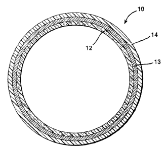
FIG. 1 illustrates a view in cross section of one embodiment of the hollow
cylindrical sleeve of the present invention;
FIG. 2 illustrates a view in cross section of another embodiment of the
hollow cylindrical sleeve of the present invention;
FIG. 3 shows a flow chart depicting process steps for fabricating a hollow
cylindrical sleeve in accordance with one embodiment of the present invention;
CA 02416841 2003-01-17
-9-
FIG. 4 illustrates a partial longitudinal sectional view of a mandrel
supporting one embodiment of the hollow cylindrical sleeve of the present
invention;
FIG. 5 is a cross-sectional view taken along line 5--5 in FIG. 4; and
FIG. 6 is a cross-sectional view of another embodiment of the invention.
DETAILED DESCRIPTION OF PREFERRED EMBODIMENTS
One embodiment of a fiber reinforced, thin-walled hollow cylindrical
sleeve 10 of the present invention is illustrated in FIG. 1. The base sleeve
12 is
fabricated from a polymer resin reinforced with a fibrous material, thereby
enabling the sleeve 10 to have a seamless surface that is adapted to be
covered
with a layer of compressible material 13 and an imageable material 14 such as
rubber, polymer, photopolymer, or any other material that can be imaged and
used in a printing process. The fibrous material may contain glass fibers,
aramid fibers, carbon fibers, metal fibers, ceramic fibers, or any other
synthetic
endless or long fibers that increases the stability, stiffness, and rigidity
of sleeve
10 such that it may accommodate conditions found in conventional graphic arts
environments.
In a preferred embodiment, the fibrous material is fiberglass. In
alternative embodiments, aramid fiber or any desired combination of fibrous
materials within the base sleeve 12 are also within the scope of the
invention.
Additionally, the fibrous material may be woven or non-woven. The fibrous
material content in the base sleeve is preferably from about 30 to about 65%
by
weight, most preferably about 50% by weight. Commercially available fibers
having desired diameters and lengths may be used.
Preferred polymer resins are those which are capable of withstanding
rubber vulcanization temperatures of up to about 160 C without softening or
degrading. Suitable polymer resins include unsaturated polyester resins such
as, for example, Synolite (trademark) and Atlac (trademark) resins
commercially
available from DSM Composite Resins, Zwolle, Netherlands, phenolic resins,
and aromatic amine-cured epoxy resins. Preferably, the base sleeve 12 has a
CA 02416841 2009-10-13
wall thickness of from between about 0.1 mm to about 0.8 mm, more preferably
between about 0.4 mm to about 0.7 mm, and most preferably about 0.68 mm.
Compressible layer 13 is applied over base sleeve 12 as shown in Fig. 1.
Preferably, compressible layer 13 has a thickness of from between about 0.5
mm to about 1.4 mm. The compressible layer may take a number of forms. For
example, in one embodiment, compressible layer 13 is provided as a sheet
material that is applied over base 12 by spirally wrapping it around the
sleeve.
Alternatively, compressible layer 13 may be wrapped around the base sleeve
and opposite ends of the sheet seamed. Adhesive may be applied to the
10 surface of base sleeve 12 or to one or both surfaces of the compressible
layer to
secure the compressible layer to base sleeve 12 and to secure imageable layer
14 to compressible layer 13.
Alternatively, compressible layer 13 may be formed by uniformly mixing
hollow microspheres with an uncured rubber and solvent and applying the
mixture over base sleeve 12. Further details of the composition of the
compressible layer may be found in Gaworoski et at, U.S. Patent No. 4770,928,
The rubber/microsphere mixture may be spread onto base sleeve 12 using a knife
or
blade to provide a uniform thickness. Alternatively, the mixture may comprise
polyurethane precursors (such as polyols and isocyanates) and be applied as a
liquid while the underlying base 12 is rotating. In this embodiment, there is
no
need for a mold, although a molding or shaping step may optionally be
utilized.
The shape and dimensions of the compressible layer may be controlled by
controlling the selection of the reactants, temperatures, and degree of
crosslinking and by applying appropriate volumetric amounts of the materials
to
the underlying base sleeve. The compressible layer may then be cured or
partially cured in place. Where a rotary casting method is utilized, there is
no
need for the use of additional adhesives to secure the compressible layer 13
to
base 12.
As shown in FIG. 1, imageable layer 14 may be applied and cured in
place on compressible layer 13 to form an integral print sleeve. In this
CA 02416841 2003-01-17
-11-
embodiment, an uncured polymer in liquid form is applied to compressible layer
13 while the sleeve is rotating. Again, desired dimensional thicknesses may be
achieved by appropriate selection of reactants, temperatures, and degree of
crosslinking and by applying appropriate volumetric amounts of the materials.
No additional adhesives are needed to secure imageable layer 14 to
compressible layer 13.
FIG. 2 illustrates another embodiment of the invention in which imageable
layer 14 is secured to compressible layer 13 via adhesive 16. Adhesive 16 may
be in the form of a thin film or tape having a thickness of between about 0.05
mm to about 1.5 mm, and may be either pressure sensitive or be activated by
heat. Again, adhesive 16 is not required where imageable layer 14 has been
formed by a casting method and cured in place.
Other methods may be used to fabricate base sleeve 12. The fibrous
material and polymer resin may be applied to the support in a variety of ways.
For example, polymer resin may be coated onto the support and the fibrous
material wound or wrapped about the polymer resin. Alternatively, the fibrous
strand or woven fabric may be impregnated with polymer resin and applied to
the support. The application of fibrous material and resin may be repeated to
build up a sufficient wall thickness for the base sleeve. The fibrous material
may
be in the form of a woven mat which is spirally wrapped about the support or
wrapped and then seamed.
Alternatively, base sleeve 12 may be manufactured by a pultrusion
process. Conventional pultrusion processes involve drawing a bundle of
reinforcing material (e.g., glass filaments or fibers) from a source. As the
fibers
are drawn from the source, the fibers are wetted and the fiber bundle
impregnated (preferably with a thermosettable polymer resin) by passing the
reinforcing material through a resin bath in an open tank. The resin-wetted
and
impregnated bundle is then pulled through a shaping die to align the fiber
bundle
and to manipulate it into the proper cross-sectional configuration. Next, the
resin is cured in a mold while maintaining tension on the filaments. Because
the
fibers progress completely through the pultrusion process without being cut or
CA 02416841 2003-01-17
-12-
chopped, the resulting products generally have exceptionally high tensile
strength in the longitudinal (i. e., in the direction the filaments are
pulled)
direction. Exemplary pultrusion techniques are described in U.S. Pat. Nos.
3,793,108 to Goldsworthy; 4,394,338 to Fuway; 4,445,957 to Harvey; and
5,174,844 to Tong.
lmageable layer 14 is formed from a material which can be imaged, either
mechanically, optically, or chemically. For example, in one embodiment of the
invention, imageable layer 14 comprises a photocurable material. A number of
photopolymeric materials are commercially available such as, for example,
Cyrel
(trademark) commercially available from DuPont and FAH II (trademark),
commercially available from BASF. The photocurable material may be in the
form of a sheet which may be applied to the base sleeve by spirally wrapping
the
sheet about the base sleeve. Alternatively, the sheet may be wrapped and
seamed. In other alternative embodiments, the photocurable material may be
applied to the base sleeve as a liquid by spreading, dipping, casting
(including
rotary casting), or molding the liquid photocurable material on the base
sleeve.
Imageable layer 14, in another embodiment of the invention, may be
formed from a natural or synthetic rubber including elastomers such as
polyurethanes and silicones. In one embodiment, uncured rubber, in the form of
a sheet, may be applied to the base sleeve by spirally wrapping the sheet
about
the base sleeve. Alternatively, the sheet may be wrapped around the base
sleeve, and opposite ends of the sheet seamed together. In an alternative
embodiment, the imageable layer may be in the form of an extruded tube which
is then mounted over the base sleeve. In still another alternative embodiment,
the imageable layer may be applied by spreading uncured rubber onto the base
sleeve.
The flow chart of FIG. 3 depicts a general representation of process steps
used to produce print sleeve 10 in accordance with one embodiment of the
present invention. In step 20, a cylindrical support, which can be comprised
of
metal, is provided. The support may be rotated to facilitate application of
the
fibrous material. In step 22, one or more layers of the fibrous material are
CA 02416841 2003-01-17
-13-
applied and wound on the rotating support. The fibrous layer is then coated in
step 24 with the polymer resin. The fibrous material may comprise a single
fiber
or a group of fibers formed into a strand or thread. The winding angle of the
fibrous material is variably adjustable in a range from 00 to 90 in the hoop
and
axial directions. The deposit speeds of the fibrous material and the tension
applied to the fibers are both adjustable within broad ranges as is known in
this
art. Steps 22 and 24 are repeated until a resulting hollow core base sleeve 12
is
produced having the desired wall thickness.
In step 26, base sleeve 12 is cured using heat and/or actinic radiation.
Alternatively, base sleeve 12 simply may be formed, and the curing step
postponed until the entire sleeve has been assembled. In step 28, the outer
surface of base sleeve 12 is worked, typically mechanically worked by
grinding,
skiving, or machining to produce a sleeve having high precision with respect
to
its wall thickness and outer diameter.
Compressible material is applied to the base sleeve in step 40. Again,
the compressible layer may be in the form of a sheet material which is wrapped
around sleeve 12, or the compressible material may be applied in uncured form
to a desired thickness and then cured or partially cured in place. In step 42
imageable material is applied over the compressible material. Again, the
imageable material may be in the form of a sheet, or may be applied as a
viscous liquid. The entire sleeve assembly is then cured. If the imageable
material is natural or synthetic rubber, the sleeve may be subjected to cure
temperatures of up to about 160 C. In step 46, the cured sleeve is worked,
typically ground, to provide a final desired wall thickness for the imageable
material and an overall diameter for the sleeve.
For example, it is possible to produce a base sleeve 12 having a length of
up to 1 meter or more and with an outer diameter of up to 100 mm or more, and
a wall thickness of between about 0.1 mm to about 0.8 mm, preferably from
about 0.2 mm to about 0.7 mm, with an outside diameter tolerance of no greater
than 0.0254mm (0.001 inch). Additionally, it is possible to produce base
sleeve
CA 02416841 2003-01-17
-14-
12 having a Total Indicated Runout (TIR) no greater than 0.0254 mm (0.001
inch), thereby ensuring good printing quality for the sleeve.
It should be apparent to those skilled in the art that a further advantage of
the print sleeve 10 in accordance with the present invention is a lower
material
cost than nickel or other metal-based sleeves. The print sleeve, because of
its
low cost, may be used as a consumable item. Another advantage includes
providing print sleeve 10 with the necessary heat resistance to withstand
vulcanization temperatures up to about 160 C that are used in conventional
rubber curing applications. Moreover, due to the seamless surface of the
sleeve, print sleeve 10 has no negative effects on the resulting print
quality, as
do some prior art print sleeves.
As the cylindrical wall of print sleeve 10 is airtight, and is capable of some
slight expansion upon the application of fluid pressure, in a preferred
embodiment, the sleeve may be mounted to a plate cylinder 30 as illustrated in
FIG. 4. Plate cylinder 30 may be of any conventional construction. In the
embodiment illustrated, cylinder 30 is provided with an air inlet 3lwhich
supplies
air under pressure into the interior of the plate cylinder from a source (not
shown). A plurality of air passageways 32 provide a path to the exterior
surface
of plate cylinder 30. Pressurized air flows through passageways 36 and acts to
expand sleeve 10 slightly, enough to permit sleeve 10 to slide easily along
the
length of cylinder 30 until it is completely mounted. Once the air pressure is
removed, sleeve 10 contracts to form a tight friction fit with plate cylinder
30.
Applying the supply of pressured fluid again, permits sleeve 10 to be
completely removed from cylinder 30. The preferred pressure of the pressurized
fluid (typically air) is from about 70 to about 112 psi (about 4.9226 to about
7.8762 kg/cm). The sleeve 10 may be mounted onto a flexographic or
rotogravure plate cylinder and is provided with a desired length such that a
proper fit is provided on the plate cylinder. Alternatively, sleeve 10 may be
mounted onto a mandrel or bridge mandrel which is in turn mounted onto a plate
cylinder. A suitable bridge mandrel is taught in commonly-assigned Busshoff,
CA 02416841 2009-10-13
U.S. Patent No. 6,276,271.
FIGS. 5 and 6 illustrate embodiments of the invention in which sleeve 10
may be used in a printing operation. In particular, FIG. 5 depicts a first
embodiment in which sleeve 10 comprises three components only, base sleeve
12, compressible layer 13, and imageable layer 14. FIG. 6 depicts another
embodiment in which plate cylinder 30 includes a compressible layer 34
thereon.
Compressible layer 34 may comprise a polymeric foam material and, in certain
instances, acts to cushion sleeve 10 to provide improved print quality.
In one application, sleeve 10 may be covered with natural or synthetic
10 rubber as the imageable layer 14 and then vulcanized by conventional means
to
produce a rubber-coated liquid transfer device. The outer surface of imageable
layer may then be laser engraved or otherwise machined as is known in the
graphic arts to provide a raised relief surface or depressions for
flexographic or
gravure printing. For example, a typical plate-on-sleeve configuration will be
a
hollow, cylindrical fiberglass composite having a wall thickness of about 0.68
mm, a compressible layer having a thickness of about 1.3 mm, and a rubber
plate having a thickness of from about 1.1 to about 1.7 mm mounted thereon
using a thin (about 0.1 mm) adhesive tape or film.
In another application, sleeve 10 may be covered with a photopolymer
and then exposed through a negative using actinic radiation. The exposed
areas are cured, and the unexposed areas are then removed to produce a
photopolymer printing plate. For example, a continuous photopolymer sleeve
will have a typical configuration of a hollow, cylindrical fiberglass
composite
having a wall thickness of about 0.68 mm, a compressible layer having a
thickness of from about 1.2 to about 1.3 mm, and a photopolymer plate thereon
having a thickness of about 1.25 mm.
The invention having being described with reference to preferred
embodiments, it will be apparent that the same may be varied in many ways.
For example, although the sleeve has been described and shown therein used
as liquid transfer rolls, the sleeve may be provided with a dielectric
coating, such
CA 02416841 2003-01-17
-16-
as alumina, and used in corona discharge systems. The sleeve also can be
provided with ceramic or metallic coatings and used as a transporter roll for
paper, film, textiles etc. Such variations are not to be regarded as a
departure
from the spirit and scope of the invention, and all such modifications as
would be
obvious to one skilled in the art were intended to be included within the
scope of
the following claims.