Note: Descriptions are shown in the official language in which they were submitted.
CA 02417080 2003-03-17
CATHODE ACTIVE MATERIAL COATED WITH A
ME'rAL OXIDE FOR INCORPORATION
INTO ~r~ LITHIUM ELECTROCHEMICAL CELL
CROSS-REFERENCE TO .RELATED APPLICATION
This applicati.o:n claims priority based on provisional
application Serial lVo. 60/351,947, filed January 24, 2002.
BACKGROLTNI) OF THE INVENTION
1. Field Of Invention
This inventiori.:relates to the conversion of chemical
energy to electrical energy. In particular, the present
invention relates to preparation of an improved cathode
material for lithium electrochemical cells containing silver
vanadium oxide (SVO) or copper silver vanadium oxide (CSVO)
coated with a protective layer of an inert metal oxide (MXOy)
or lithiat.ed metal oxide (LiXM~,Oz) . For example, the new
active material contains a core of ~-phase SVO providing the
cell with relatively high capacity and rate capability. A
protective coating o:E MXOy or Li;XMI,OZ on the active material
reduces particle reaac tivity with electrolyte and improves the
long-term stabilit5~~ of the cathode. Improved long-term
stability of the cathode active material translates into
increased life upon incorporation into a lithium
electrochemical ce~;.l. An exemplary application is having the
cell power an implo.ntable cardiac defibrillator, where the
cell may ~-un under a light load for extended periods of time
interrupted by high rate pulse discharge.
CA 02417080 2003-03-17
2
2. Prior A:rt
As is well known by those skilled in the art, an
implantable cardiac ~aefibrillator is a device that requires a
power source for a generally medium rate, constant resistance
load component provi~::ied by circuits performing such functions
as, for example, the heart sensing and pacing functions.
From time-to-time, t:hae cardiac defibrillator may require a
generally high rate, pulse discharge load component that
occurs, for example, during charging of a capacitor in the
defibrillator for thr: purpose of delivering an electrical
shock to th~~ heart t.;:> t.reat tachyarrhythmias, the irregular,
rapid heartbeats than: can be fatal if left uncorrected.
It is generally recognized that for lithium cells,
silver vana~3ium oxide: (SVO) and, in particular, E-phase
silver vanadium oxide (AgV205.s), is preferred as the cathode
active material. U.;:~. Patent Nos. 4,310,609 and 4,391,729,
both to Liang et al., disclose the preparation of e-phase SVO
as a cathode material for use in a nonaqueous electrolyte
electrochemical cell. These patents describe the preparation
of silver vanadium o:~i.de through the use of a. thermal
decomposition reaction of silver nitrate with vanadium oxide
(V205) at a maximum t:etnperature of -360°C. The Liang et al.
patents are assigned to the assignee of the present invention
and incorporated herein by reference.
Silver vanadium oxide is preferred for cardiac
defibrillators because of its relatively high rate
capability. For example, U.S. Patent No. 4,830,940 to
Keister et al. disclo:~es a primazy cell containing silver
vanadium oxide for delivering high current pulses with rapid
recovery, high capacil:y and low self-discharge. The Keister
et al. patent is assigned to the assignee of the present
CA 02417080 2003-03-17
3
invention and incorporated herein by reference.
A discussion related to the surface modification of
inorganic :particles is found in U.S. Patent No. 3,905,9x6 to
Hawthorne. This patent describes the surface treatment of
active particles with chemically bonded organic aluminum
derivatives of the formula (RO)nAlR'3_". The chemically bonded
layer confers improved mechanical properties on the active
material. However, these coatings were applied at relatively
low temperatures and were not heat treated to decompose the
A1 coating to a metal oxide.
U.S. Patent 6,256,972 B1 to Hong et a1. discloses
coating a :1~i0 cathode used for a molten carbonate fuel cell
with LiCo02 prepareca by a sol-ge.1 process. A sol is prepared
using stoichiometric amounts of lithium and cobalt salts in a
solvent with or without adding a chelating agent. The Ni0
electrode is impregnated with th.e sol and the electrode dried
under vacuum and calcined. The heat treatment (calcining)
temperature is not s~>ecified in this patent, however, LiCo02
materials are typically heat treated to about 700°C to about
1000°C to :Eorrn this miaterial.
In th.e paper: "Modification of LiXNil_yCoY02 By Applying a
Surface Coating of M<~O", Kweon, H.J.; Kim, S.J.; Park, D.G.
J. Power Sources 2000, 88, 255-261, the authors described
coating a LiXNil_yCo,,,4~ cathode material with a surface layer
of MgO. 'fhe modified cathode active material displayed
improved cycle reversibility for rechargeable lithium-ion
cells . Th.e LiXNil_yrtrc>~,.OZ particles were coated with a magnesia
xerogel [Mg(OMe)2] and heated at 750°C for 12 hours to form
the protective Mg0 coating.
CA 02417080 2003-03-17
4
SUMMARY OF 'PHE INVEN':fION
Accordingly, th~:y;present invention provides a process
for preparing a composite SVO cathode material containing a
SVO (E-phase Ag2V4011 4:~r ~r-phase Ag~,,8V20;_4) or CSVO core coated
with a protective metal oxide or lithiated metal oxide
surface layE~r. The coating can include Sn02, Si02, A1203,
Zr02, BZO3, MgO, LiCoC)2, Mn02, Li.MnOX, and mixtures thereof .
These materials are preferably applied via a sol-gel process
to provide ~~ thin coating over the SVO or CSVO core. This
results in ~~ new comF:ro,site material with improved performance
over prior art cathode active materials. In particular,
voltage delay and Rdc :build-up during long-term cell
discharge are reduced since the cathode active material is
isolated from the elE:~ctrolyte.
These <ind other objects of the present invention will
become increasingly more apparent to those skilled in the art
by referenrea to the i:ollowing description and to the appended
drawings.
BRIEF DESCRCPTION OF THE DRAWINGS
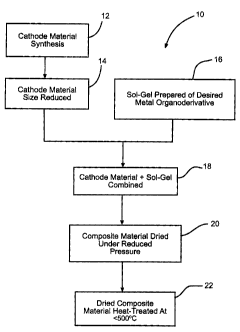
Fig. 1 is a flow chart illustrating the processing steps
for coating a particle of active material with a metal oxide
according t« the present invention.
Fig. 2 is a schematic of a patient P provided with an
implantable medical device 100.
Fig. :3 is an enlarged schematic of the indicated area in
Fig. 2 particularly showing the control circuitry 104, the
electrochemical cell 1.06 and capacitor 108 for the medical
device 100 ~~onnected t:o the patient's heart H.
CA 02417080 2003-03-17
5
DETAILED DESCRIPTION OF THE PREFERRED EMBODIMENTS
As used herein, the term "pulse" means a short burst of
electrical current ~;>f significantly greater amplitude than
that of a pre-pulse current immediately prior to the pulse.
A pulse train consi::~ts of at least two pulses of electrical
current delivered i:n relatively short succession with or
without open circuit rest between the pulses. An exemplary
pulse train may con::~ist of four 10-second pulses (23.2 mA/cm2)
with a 15 .second rest between each pulse. A typically used
range of current densities for cells powering implantable
medical devices is .from about 15 mA/cmz to about 50 mA/cm2,
and more preferably from about 18 mA/cm2 to about 35 mA/cm2.
Typically, a 10 second pulse is suitable for medical
implantable applications. However, it could be significantly
shorter or longer depending on the specific cell design and
chemistry.
An electrochemical cell that possesses sufficient energy
density and discharges capacity required to meet the vigorous
requirements of implantable medical devices comprises an
anode of a metal selected from Groups IA, IIA and IIIB of the
Periodic Table of the Elements. Such anode active materials
include lithium, sodium, potassium, etc., and their alloys
and interm.etallic compounds including, for example, Li-Si,
Li A1, Li--B and Li-5i--B alloys and intermetallic compounds.
The preferred anode comprises lithium. An alternate anode
comprises a lithium alloy such as a lithium-aluminum alloy.
The greater the amounts of aluminum present by weight in the
alloy, however, the lower the energy density of the cell.
The form of tr:~e anode may vary, but preferably the anode
is a thin metal shewet or foil of. the anode metal, pressed or
CA 02417080 2003-03-17
6
rolled on a metallic anode current collector, i.e.,
preferably c:omprisinct titanium, titanium alloy or nickel, to
form an anode component. Copper, tungsten and tantalum are
also suitab:Le materials for the anode current collector. In
the exemplary cell ot' the present invention, the anode
component h<~s an extended tab at lead of the same material as
the anode current co:Llector, i.e., preferably nickel or
titanium, integrally formed therewith such as by welding and
contacted b~l a weld to a cell case of conductive metal in a
case-negative electrical configuration. Alternatively, the
anode may be formed in some other geometry, such as a bobbin
shape, cylinder or pellet to allow an alternate low surface
cell design.
The electrochemical cell of the present invention
further comprises a ~;~athode of electrically conductive
material th~~t serves as the other electrode of the cell. The
cathode is preferabl;~r of solid materials comprising a metal
element, a .metal oxide, a mixed metal oxide and a metal
sulfide, and combinations thereof. The cathode active
material is formed by the chemical addition, reaction, or
otherwise intimate contact of various metal oxides, metal
sulfides and/or metal elements, preferably during thermal
treatment, sol-gel formation, chemical vapor deposition or
hydrothermal synthesi;~ in mixed states. The active materials
thereby produced contain metals, oxides and sulfides of
Groups, IB, IIB, III:B,, TVB, VB, VIB, VIIB and VIII, which
includes the noble metals and/or other oxide and sulfide
compounds. A preferred cathode active material is a reaction
product of at least silver and vanadium.
One preferred mixed metal o~cide has the general formula
SMxVZOy where SM is a metal selected from Groups IB to VIIB
CA 02417080 2003-03-17
7
and VIII of the Periodic Table of Elements, wherein x is
about 0.30 to 2.0 and y is about 4.5 to 6.0 in the general
formula. By way of i.~.lustration, and in no way intended to
be limiting, one exemplary cathode active material comprises
silver vanadium oxi~;is~ having t=he general formula AgXV20Y in
any one of its many phases, i.e., ~i-phase silver vanadium
oxide having in the General formula x = 0.35 and y = 5.8, y-
phase silver vanadium oxide having in the general formula x =
0.74 and y = 5.37 a,nd ~-phase silver vanadium oxide having in
the general formula x = 1.0 and y = 5.5, and combinations and
mixtures of phases thereof. For a more detailed description
of such cathode active materials reference is made to the
previously discussed Liang et al. patents.
Another prefer:rE:d composite metal oxide cathode material
includes V20Z wherein z <- 5 combined with AgzO with silver in
either the silver(I:L), silver(I) or silver(0) oxidation state
and Cu0 with copper in either the copper(II), copper(I) or
copper(0) oxidation :Mate to provide the mixed metal oxide
having the general formula CuXAgyVZOZ, (CSVO). Thus, the
composite cathode active material may be described as a metal
oxide-metal oxide-metal oxide, a metal-metal oxide-metal
oxide, or a metal-metal-metal oxide and the range of material
compositions found for CuxAgyV2OZ is preferably about 0.01 <_ z
S 6.5. Typical forrm.~ of CSVO are Cuo.lsAgo.s7VzOZ with z being
about 5 . 5 and Cuo _ SAgo , sVzOz wi th z being about 5 . 7 5 . The
oxygen content is designated by z since the exact
stoichiometric proportion of oxygen in CSVO can vary
depending on whether the cathode material is prepared in an
oxidizing atmosphez'e such as air or oxygen, or in an inert
atmosphere such as argon, nitrogen and helium. For a more
detailed ctescriptican of this cathode active material
CA 02417080 2003-03-17
8
reference is made to U'.S. Patent t~os. 5,472,810 to Takeuchi
et al. and !i,516,340 to Takeuchi et al., both of which are
assigned to the assi;.~n.ee of the present invention and
incorporated herein :by reference. In addition to silver
vanadium oxide and c::>p~per silver vanadium oxide, V205, Mn02,
LiCo02, LiNi.02, LiMnO;z, LiMn204, TiS2, CuzS, FeS, FeS2, Ag20,
Ag202, CuF, AgzCr04, co;p;per oxide, copper vanadium oxide, and
mixtures thereof are useful as the cathode active material.
Fig. 1 shows a flaw chart that illustrates the process
used to :form the metal oxide or lithiated metal oxide
coated SVO or CSVO particles according to the present
invention. The process begins with 12 of the cathode active
material. :In the case of SVO, the active material can be
prepared according to any known synthesis method. These
include the synthesise techniques described in U.S. Patent
Nos. 4, 016,:338 to La~~ck, 4, 158,'722 to Lauck et al. , 4, 310, 609
to Liang et al., 4,391.,729 to Liang et al., 4,542,083 to Cava
et al., 4,6'75,260 to ~~akurai et al., 4,751,157 to Uchiyama et
al., 4,751,158 to Uchi.yama et al., 4,803,137 to Miyazaki et
al., 4,830,:940 to Keister et al., 4,964,877 to Keister et
al., 4,965,151 to Ta:keda et al., 5,194,342 to Bito et al.,
5,221,453 to Crespi, 5,298,349 to Takeuchi, 5,389,472 to
Takeuchi et al., 5,54°_i,497 to Takeuchi et al., 5,458,997 to
Crespi et al., 5,472,810 to Takeuchi et al., 5,498,494 to
Takeuchi et al., 5,49F3,495 to Takeda et al., 5,512,214 to
Koksbang, 5,516,340 to Takeuchi et al., 5,558,680 to Takeuchi
et al., 5,567,538 to Oltman et al.., 5,670,276 to Takeuchi et
al., 5,695,892 to Leising et al., 5,895,733 to Crespi et al.,
5,955,218 to Crespi et al., 6,093,506 to Crespi et al.,
6,130,055 to Crespi et al., and E~,413,669 to Takeuchi et al.
Prior art synthesis for SVO are also described in Leising, R.
CA 02417080 2003-03-17
9
A.; Takeucfai, E. S. Chem. Mater. 1993, 5, 738-742 and
Leising, R. A.; TakEau~~hi, E. S. Chem. Mater. 1994, 6, 489-
495. The latter Lei.sing et al. publication describes a
preferred method for. the synthesis of SVO with the caveat
that the temperature is :less than 500°C: to fully form the
material. These patents and publications are incorporated
herein by reference.
Next, the particle size of the cathode active material
is reduced in step 't4. This increases the material's surface
area, which is beneficial for improved discharge efficiency.
Several means are contemplated for reducing the size of the
active particles im.~.l.uding using a mortar and pestle, a ball
mill, jet-mill, or b~~ attrition. In addition, the SVO or
CSVO materials may :be used directly without particle size
reduction.
A so:l-gel solution 16 containing an organic derivative
of the desired coating metal is prepared. The sol-gel
solution can either be an aqueous or a non-aqueous based
solution. Aqueous solutions include water and a minor amount
of lithium hydroxide to bring the solution t:o a basic pH.
Nonaqueou~; solutiorks are essentially alcohol based with
methanol, ethanol, isopropyl and isobutyl being preferred.
Useful metals for this purpose include aluminum, boron,
cobalt, magnesium, manganese, silicon, tin, and zirconium.
Lithium se~lts of trxese metals may also be added to the sol-
gel solution 16 to produce a lithiated metal oxide coating.
Either th~a SVO or ~:SVO material, or both, is then added to
the sol-gel solution to form a mixture in step 18. In this
step, it is important to carefully control the ratio of SVO
or CSVO to sol-gel. Preferably, the solution contains, by
weight, a ratio of coating material to active material in a
CA 02417080 2003-03-17
ZO
range of about 1:3 to about 1:20, 1:5 being preferred. The
resulting coated cathode active material is dried in step 20
under a reduced pressure in a range of about 20 inches of Hg.
to about 50 inches of Hg., preferably about 3U inches of Hg.,
to remove the carrierw solvent from the sol-gel..
The dried coated. material is heat-treated in step 22 to
form a metal. oxide oi~:Lithiated metal oxide coating on the
SVO or CSVO particles. The heat t:.reatment step is critical
to controlling the composition of the product. The heating
range is about 200°C to about 500°C for a time of about 10
minutes to about 6 h<~urs. Longer heating are required for
lower temperatures. The maximum 'heating temperature is
preferably below about 500°C. The protective coatings have
the general formula ~::>f MXO,, or LiXMyOz wherein M is selected
from the group consisting of Al., B, Mg, Mn, Si, Sn, and Zr.
In the formula MxOY, :x = 1 or 2 and y = 1 to 3 while in the
formula LiXMyO~, x = ~, y = 1 or 2 and z = 1 to 4. Exemplary
coatings far SVO or CSVO include Sn02, Si02, A1203, Zr02, B203.
MgO, Mn02, LiCo02, Li.MnXOY, and mixtures thereof .
Unlike the prior art coated cathode preparations of the
previously described.Hawthorne arid Hong et al. patents,
relatively high temperatures (>500°C) produce poor SVO or CSVO
cathode active materials regardless of whether the material
is being coated, or not. The amount of time the composite
material i~~ heated p.s also import:.ant in determining the final
product. Relatively ;long reaction times are to be avoided
because they promote ion diffusion of metal atoms from the
coating to migrate t~.o the SVO or CSVO core, as ion diffusion
is particularly rap~..d in these materials. Thus, the time and
temperature paramete:~rs are key specific factors related to
this invention.
CA 02417080 2003-03-17
11
Before fabrication into an electrode structure for
incorporation into an electrochemical cell according to the
present invention, the r~athode active material prepared as
described above is prE=ferably mired with a binder material
such as a f>owdered f:luoro-polymer. , more preferably powdered
polytetraf).uoroethyJ.ene or powdered polyvinylidene flouride
present at about 1 too about S weight percent of the cathode
mixture. Further, up to about 1U weight percent of a
conductive diluent a.s preferably added to the cathode mixture
to improve conductivity. Suitable materials fox this purpose
include acetylene bJ..ack, carbon black and/or graphite or a
metallic powder such as powdered nickel, aluminum, titanium
and stainla_ss steel. The preferred cathode active mixture
thus includes a pow~aered fluoro-polymer binder present at
about 3 weight percent, a conductive diluent present at about
3 weight percent anti about 94 weight percent of the cathode
active material.
Cathode components for incorporation into an
electrochemical cell according to the present invention are
prepared by rolling, spreading or pressing the cathode active
material onto a suitable current collector selected from the
group consisting of stainless steel, titanium, tantalum,
platinum, aluminum, gold, nickel, and alloys thereof. The
preferred current c:oll.ectar material is titanium, and most
preferabl~~ the tita.n:ium cathode current collector has a thin
layer of c~raphite/carbon paint applied thereto. Cathodes
prepared as described above may be in the form of one or more
plates operatively associated with at least one or more
plates of anode material, or in the form of a strip wound
with a corresponding strip of anade material in a structure
similar t~~ a "jellyroll".
CA 02417080 2003-03-17
12
The cathode current collector is connected to a terminal
insulated from the cell casing (not shown) by a suitable
glass-to-metal seal. This describes a case-negative cell
design, which is the preferred form of the present invention
cell. The cell can al:ao be built in a case-positive design
with the cathode current collector contacted to the casing
and the anode current. collector connected to a terminal lead
insulated from the casing. In a further embodiment, the cell
is built in a case-neutral configuration with both the anode
and the catraode connected to respective terminal leads
insulated from the casing. These terminal constructions are
well known by those skilled in the art.
In ordE~r to prevent internal short circuit conditions,
the cathode is separated from the Group IA, IIA or IIIB anode
by a suitab.~e separator material. The separator is of
electrically insulata_ve material, and the separator material
also is chemically unreactive with the anode and cathode
active materials and both chemically unreactive with and
insoluble irl the electrolyte. In addition, the separator
material has a degree of porosity sufficient to allow flow
there through of the electrolyte during the electrochemical
reaction of the cell. Illustrative separator materials
include fabrics woven from fluoropolymeric fibers including
polyvinylidine fluoride, polyethylenetetrafluoroethylene, and
polyethylenechlorotrifluoroethylene used either alone or
laminated with a fluoropolymeric microporous film, non-woven
glass, polypropylenes, polyethylene, glass fiber materials,
ceramics, polytetrafluoroethylene membrane commercially
available Lmder the designation ZITEX (Chemplast Inc.),
polypropylE~ne/polyet.hylene membrane commercially available
under the designation CELGARD (Celanese Plastic Company,
CA 02417080 2003-03-17
1. 3
Inc.), a membrane commercially available under the
designation. DEXIGLA~; (C.H. Dexter, Div., Dexter Corp.), and a
polyethylene membrar.~.e commercially available from Tonen
Chemical Carp.
The e7_ectrochemical cell of the present invention
further includes a nonaqueous, ionica:Lly conductive
electrolyte' that see°ves as a medium for migration of ions
between them anode arid the cathode electrodes during the
electrochemical reactions of the cell. The electrochemical
reaction at. the ele<.arodes involves conversion of ions in
atomic or molecular forms that migrate from the anode to the
cathode. '.Chus, nonaqueous electrolytes suitable for the
present invention az-e substantially inert to the anode and
cathode ma~teriais, aan.d they exhibit those physical properties
necessary for ionic transport, namely, low viscosity, low
surface tension and wettability.
A suitable electrolyte has an inorganic, sonically
conductive salt dissolved in a mixture of aprotic organic
solvents comprising a low viscosity solvent and a high
permittivity solvent.. In the case of an anode comprising
lithium, preferred lithium salts that are useful as a vehicle
for transport of lithium ions from the anode to the cathode
include Li.PFs, LiBF4, LiAsF6, LiSbF6, LiC104, Li02, LiA1C14,
LiGaCl4 , LiC ( S02CF3 ) 3 , LiN ( SOZCF3 ) z , Li SCN, Li03SCF3 , LiC6FSS03 ,
LiOZCCF3, LiSO6F, Li.B (C6H5) y, LiCF3S03, and mixtures thereof .
Low ~riscosity solvents useful with the present invention
include esters, linear and cyclic ethers and dialkyl
carbonates such as tetrahydrofuran (THF), methyl acetate
(MA), dig:lyme, trigylme, tetragylme, dimethyl carbonate
(DMC), 1,?-dimetho:~:yethane (D ME), 1,2-diethoxyethane (DEE),
1-ethoxy,.Z-methoxy4~thane (E ME), ethyl methyl carbonate,
CA 02417080 2003-03-17
14
methyl propel carbonate, ethyl propyl carbonate, diethyl
carbonate, dipropyl c°arbonate, and mixtures thereof, and high
permittivity solvents include cyclic carbonates, cyclic
esters and cyclic ami.d~es such as propylene carbonate (PC),
ethylene carbonate (i~C), butylene carbonate, acetonitrile,
dimethyl sul.foxide, <:~i:methyl formamide, dimetx-zyl acetamide,
y-valerolact:one, Y-butyrolactone (GBL),
N-methyl-2-pyrrolidorxe (NMP), and mixtures thereof. In the
present invfantion, the preferred anode is lithium metal and
the preferred electrolyte is 0.8M to 1.5M LiAsF6 or LiPF6
dissolved in a 50:50 mixture, by volume, of propylene
carbonate and 1,2-dimethoxyethane.
The corrosion rn::istant glass used in the glass-to-metal
seals has u;p to about 50'k by weight silicon such as CABAL 12,
TA 23, FUSI'TE 425 or F'USITE 435. The positive terminal leads
preferably comprise molybdenum, although titanium, aluminum,
nickel alloy, or stainless steel can also be used. The cell
casing is an open container of a conductive material selected
from nickel, aluminum, stainless steel, mild steel, tantalum
and titanium. The caring is hermetically sealed with a lid,
typically of a material similar to that of the casing.
The coated-SVO and CSVO particles are particularly
useful in electrochemical cells containing lithium anodes and
non-aqueous: electrolytes. In a typical cell, the cathode
consists oi: a mixtu~:ve of, by weight, about 94$ coated-SVO
along with 3$ PTFE, 2~ graphite and 1~ carbon black. The
cathode is separateci from the lithium anode by a layer of
polypropylene separator. The cell is activated with 1 M
LiAsF6 in F~C/DME (1:1) electrolyte. Pulse testing of the cell
is accomplished by ~u.bjected it to high current pulses (--23
mA/cm2) for 10 seconds in duration. The current pulses are
CA 02417080 2003-03-17
15
applied in groups of four, with 15 seconds of rest between
pulses. Time between application of the pulse groups ranges
from several weeks to six months. Total discharge time for
the cell is up to ten years. 'this makes the cell
particularly well suited for powering an implantable medical
device, such as a cardiac pacemaker, cardiac defibrillator,
drug pump, neurostimulator, self--contained artificial heart,
and the 1 i ><:e .
Figs. 2 and 3 show a patient P having a medical device
100, such .as an implantable cardiac defibrillator, implanted
inside the body. The enlarged schematic shows the medical
device 100 comprising a housing 102 containing control
circuitry 104 powerad by an electrochemical cell 106
according to the pre:~ent invention. The cell 106 is also
connected to a capacitor 1.08. The control circuitry 104 is
connected to at least one conductor 110 by a hermetic
feedthrough 112, air is well known by those skilled in the
art. The distal eryd of the conductor connects to the heart H
for delivering a therapy thereto from the capacitor 108
charged by the cell. 106.
Periodically, the patient will go to a medical facility,
and the like, where the deliverable capacity determined by
the control circuitry 104 is read to determine if the cell
106 has discharged to the paint that it is approaching its
end-of-life, typically at an open circuit voltage of about
2.0 volts. If so, this indicates that it is time for the
physician to schedule the patient for surgery to replace the
medical dE:vice witl.~ a new one .
It i;s appreciat.ed that various modifications to the
inventive concepts described herein may be apparent to those
of ordinary skill in the art without departing from the
CA 02417080 2003-03-17
16
spirit and s~~ope of tie present invention as defined by the
appended claims.