Note: Descriptions are shown in the official language in which they were submitted.
CA 02417114 2007-12-12
-1-
Electrical Connector
Field of the Invention
The invention relates to an electrical plug connector, a cable manager for an
electrical plug connector,
a method for assembly of an electrical plug connector, and a tool for assembly
and connection of the
cores of the electrical plug connector.
Background of the Invention
EP 0 445 376 B1 discloses a plug connector for connecting a plug to
electrically insulated conductors,
having a housing which has a cavity to accommodate the plug, and with a first
and a second set of
connecting elements being provided. Each connecting element in the first set
has an insulation-
displacement contact for holding an insulated conductor and for making a
contact connection with its
core, and has a foot section. Each connecting element in the second set has a
contact strip and a
contact tongue, with each of the connecting elements in the second set being
electrically connected via
the contact tongue to the foot section of the connecting elements in the first
set and extending from the
first set to the cavity in order thus to make an electrical connection to the
contacts fitted to the plug,
and with the first and the second set of connecting elements being fixed in
their position in the housing
of the plug connector by guide means. The connection between the conductors
and the insulation-
displacement contacts is in this case made by means of known connection tools.
In the process, the
individual conductors or cores must be routed to the insulation-displacement
contact and must be
pressed into the insulation-displacement contact by means of the connection
tool. One disadvantage
of the known plug connector is its wide tolerances in its transmission
response, which lead to major
problems at high transmission rates.
The invention is thus based on the technical problem of reducing the
tolerances in the transmission
response of a plug connection. A further technical problem is the provision of
a method for assembly
of an electrical plug connector and of a tool for assembly of the plug
connector, and for the connection
of the cores of the electrical plug connector.
Summary of the Invention
In an aspect of the invention there is provided an electrical plug connector,
comprising a plug
connector housing, a printed circuit board with two sets of contact elements,
the first set of contact
elements being arranged on a front face of the printed circuit board and
projecting into an opening in
the plug connector housing, and the second set of contact elements being
arranged on a rear face of
the printed circuit board, the contact elements of the second set are in the
form of insulation-
displacement contacts, wherein the plug connector comprises a cable manager
which has a through-
opening and is formed on a front face thereof with guides for cores which are
intended to make contact
with the insulation-displacement contacts, in which case the guides in the
region of the insulation-
displacement contacts are formed with recessed holders for the insulation-
displacement contacts; the
CA 02417114 2006-11-09
-2-
cable manager can be latched to the plug connector housing; and the guides run
parallel, with two
guides being arranged in each quadrant of the cable manager.
In another aspect of the invention there is provided a cable manager for an
electrical plug connector,
including openings which extend from a rear face to a front face thereof;
wherein the cable manager is
designed with guides on the front face for cores which are intended to make
contact with insulation-
displacement contacts, with the guides in the region of the insulation-
displacement contacts being
designed with recessed holders for the insulation-displacement contacts.
In yet another aspect of the invention there is provided an electrical plug
connector, comprising: a plug
connector housing; a printed circuit board; a first set of contact elements; a
second set of contact
elements, the first set of contact elements being arranged on a front face of
the printed circuit board
and projecting into an opening in the plug connector housing, the second set
of contact elements being
arranged on the rear face of the printed circuit board, the contact elements
of the second set of contact
elements being in the form of insulation-displacement contacts; and a cable
manager having a front
face and a rear face, the cable manager including: a through-opening located
in a central region of the
cable manager, the through-opening extending from the front face to the rear
face of the cable
manager; and guides formed on the front face of the cable manager, the guides
being configured to
receive wire cores which are intended to make contact with the insulation-
displacement contacts, the
guides in a region of the insulation-displacement contacts being formed with
recessed holders for the
insulation-displacement contacts; the cable manager being latchable to the
plug connector housing.
In a further aspect of the invention there is provided an electrical plug
connector, comprising: a plug
connector housing; a printed circuit board; a first set of contact elements; a
second set of contact
elements, the first set of contact elements being arranged on a front face of
the printed circuit board
and projecting into an opening in the plug connector housing, the second set
of contact elements being
arranged on the rear face of the printed circuit board, the contact elements
of the second set of contact
elements being in the form of insulation-displacement contacts; a cable
manager with a through-
opening, the cable manager being formed on a front face with guides for wire
cores which are intended
to make contact with the insulation-displacement contacts, the guides in a
region of the insulation-
displacement contacts being formed with recessed holders for the insulation-
displacement contacts,
the cable manager being latchable to the plug connector housing; and a cable
grip arranged above the
cable manager, wherein the cable grip includes a number of parts including a
first part with two jaw
parts which flex jointly with a joint flexing limited in an adjustable manner
by a spring engaging around
the jaw parts, and with a third part closure element which can be latched in
an adjustable manner to
the first part and/or to the spring, whereby a cable to be attached can be
centered in a defined, force-
fitting manner.
CA 02417114 2006-11-09
-2a-
In yet a further aspect of the invention there is provided a method for
assembly of an electrical plug
connector with a plug connector housing, a printed circuit board, a first set
of contact elements, a
second set of contact elements, the first set of contact elements being
arranged on a front face of the
printed circuit board and projecting into an opening in the plug connector
housing, the second set of
contact elements being arranged on a rear face of the printed circuit board,
the contact elements of the
second set of contact elements being in the form of insulation-displacement
contacts and a cable
manager with a through-opening located within a central region of the cable
manager, the cable
manager including guides for wire cores which are intended to make contact
with the insulation-
displacement contacts, the guides in a region of the insulation-displacement
contacts being formed
with recessed holders for the insulation-displacement contacts, the cable
manager being latchable to
the plug connector housing, the method comprising the following method steps:
inserting the printed
circuit board into the plug connector housing; passing the cores of a cable
with which contact is to be
made through the through-opening of the cable manager from a rear face of the
cable manager to a
front face of the cable manager, with the cores being pressed into the
associated guides on the front
face of the cable manager and being cut off at side edges of the cable
manager; aligning the cable
manager with respect to the insulation-displacement contacts on the printed
circuit board; and latching
the cable manager to the plug connector housing, wherein the latching causes
the cores to make
contact with the insulation-displacement contacts.
To this end, the plug connector comprises a cable manager which has a through-
opening and is
formed on the front face with guides for cores which are intended to make
contact with the insulation-
displacement contacts, in which case the guides in the region of the
insulation-displacement contacts
are formed with recessed holders for the insulation-displacement contacts, and
the cable manager can
be latched to the plug connector housing. This results in a number of major
advantages in comparison
to the prior art, which restrict the transmission response tolerances. The
guides fix the length of the
cores with which contact is to be made, in a defined manner. For this purpose,
the respective core is
passed through the openings and is inserted into the guides. Projecting parts
of the core are then cut
off at the edge of the cable manager, so that the length of the cores is the
same in each plug
connector. Furthermore, the guides mean that the cores can each all be located
in a reproducible
position with respect to one another. These two facts result in a fixed value
for the crosstalk. A further
advantage is that, once the cores have been fitted in the cable manager,
contact between them and
the insulation-displacement contacts can be made simultaneously, or virtually
simultaneously.
To this end, the rear face of the cable manager is formed with an incline on
one side. The cable
manager and plug connector housing can be latched to one another without
exerting any
relatively high force, by means of an essentially, U-shaped tool like a
bracket, on whose lower
limb face, parallel-running guides are arranged which point inward, run at
right angles to the rear wall
of the tool, and are designed with obliquely running guide edges in the upper
region on the inside of the
limbs. In this case, the inclines on the cable manager and on the tool are
aligned to be complementary
to one another, so that the process of pushing the tool on leads to a travel
movement, by means of
CA 02417114 2006-11-09
-2b-
which the cable manager is moved in the direction of the plug connector
housing, so that the
insulation-displacement contacts cut through the insulation on the cores and
enter the holder within the
guides. The transformation ratio from the sliding movement to the travel
movement can in this case be
varied via the gradient of the inclines.
A guide cross is preferably arranged in the opening in the cable manager, so
that the cores are also
guided in a defined manner within the openings. In the case of known RJ-45
plug connections, the
associated core pairs are in this case each guided in one segment of the guide
CA 02417114 2003-01-24
-3-
cross.
In order to reduce the defined crosstalk in the contact area as much as
possible, the cores of
different pairs are guided and made contact with at a distance from one
another.
To this end, the guides run, for example, radially from the opening into the
comers of the cable
manager.
In another preferred embodiment, all the guides run parallel, but in different
sectors of the cable
manager.
In a further preferred embodiment, a hold-down device is arranged between the
cable manager
and the printed circuit board and allows the printed circuit board to be fixed
with respect to the
plug connector housing. Tensile forces on the cable, which would otherwise act
on the printed
circuit board, are thus absorbed.
In a further preferred embodiment, the guides are at offset levels in either
direction with respect
to one another, so that some of the cores make contact with one another at
different times. This
also results in the necessary contact forces being distributed better, so that
the user requires
less force for assembly and connection.
A cable grip is preferably arranged above the cable manager, in order to
absorb tensile forces
on the cable.
In a further preferred embodiment, the cable grip is designed with a number of
parts, with the
assembly tool at the same time forming a part of the cable grip.
To this end, the tool or the first part of the cable grip comprises two jaw
parts which are located
together and whose joint flexing can be limited by means of a spring which
engages around the
jaw parts and can be inserted at different points on the first part. A force-
fitting connection to the
cable can be produced by means of a third part, which can be latched to the
first part and/or to
CA 02417114 2003-01-24
-4-
the spring. In addition to the force-fitting connection, this multipart cable
grip also allows cables
of different diameter to be centered, which in tum has a positive effect on
the tolerances relating
to the transmission response.
In the case of cables with a shield, the cable grip can, furthermore, be used
as a universal shield
contact. To this end, the first and the third parts of the cable grip are
either in the form of a die-
cast zinc part or a metallized plastic part, which is or can be connected to a
ground plate in the
plug connector housing.
The invention will be explained in more detail in the following text with
reference to a preferred
exemplary embodiment. In the figures:
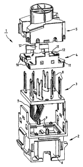
Figure 1 shows an exploded illustration of a plug connector,
Figure 2 shows a perspective illustration of a cable manager from the rear
face,
Figure 3 shows a plan view of the front face of a first embodiment of a cable
manager,
Figure 4 shows a plan view of a front face of a second embodiment of a cable
manager,
Figure 5 shows a perspective illustration of a tool for assembling the plug
connector,
and/or a first part of a cable grip,
Figure 6 shows a perspective illustration of a cable grip in the open state,
Figure 7 shows a perspective illustration of a cable grip in the closed state
without
any cable,
Figure 8 shows a side view of the electrical plug connector with the first
part or tool
partially pushed on,
Figure 9 shows a perspective illustration of the assembled plug connector with
the
cable grip and cable,
Figure 10 shows a perspective illustration of a cable manager from the rear
face, and
Figure 11 shows a plan view of the front face of a third embodiment of a cable
manager.
CA 02417114 2003-01-24
Figure 1 shows an exploded illustration of a plug connector 1. The plug
connector 1 comprises a
plug connector housing 2, a printed circuit board 3, a hold-down device 4 and
a cable manager
5. The plug connector housing 2 in the illustrated example is in the form of a
socket housing with
various latching and insertion means. The plug connector housing 2 is designed
with a shielding
plate 6 on the side surfaces. The printed circuit board 3 is fitted with a
first set of contacts 7 on
its front face and with a second set of insulation-displacement contacts 8 on
its rear face. One
contact 7 in the first set is in each case connected to one contact 8 in the
second set. The
printed circuit board 3 is then inserted into the plug connector housing 2. In
the process,
cylindrical pins 9 on the plug connector housing 2 pass through holes in the
printed circuit board
3, so that the plug connector housing 2 and printed circuit board 3 can be
adjusted and fixed
with respect to one another. The contents 7 in the first set, which are in the
form of RF contacts,
then project into an opening which is accessible from the front face of the
plug connector
housing. The hold-down device 4 is then pushed over the contacts 8 in the
second set, and is
latched to the plug connector housing 2. For this purpose, the hold-down
device 4 is designed
with latching tabs 10 on the end face, and has through-openings 11 for the
insulation-
displacement contacts 8. Furthermore, the hold-down device 4 is designed with
two latching
hooks 12, which-are used for latching to the cable manager 5. Before
describing this assembly
process, the cable manager 5 will first of all be explained in more detail
with reference to Figures
2-4.
The cable manager 5 is essentially cuboid and has a central opening 13 around
which a
cylindrical attachment 14 is arranged. The opening 13 extends through from the
rear face 15 to
the front face 16. A guide, cross 17 is arranged in the opening 13, and
subdivides the opening 13
into four segments. Half of the rear face 15 is in the form of an incline 18.
The cable manager 5
is designed with guides 19 on the front face 16, into which the cores with
which contact is to be
made can be inserted. Each guide 19 is designed with a recessed holder 20. The
holders 20 are
in this case arranged at the same positions as the insulation-displacement
contacts 8 in Figure
1. The guides 19 run either radially from the opening 13 to the edges of the
cable manager 5 (as
illustrated in Figure 3), or each run parallel to one another (as illustrated
in Figure 4). In this
case, if there are eight guides 19, as are required, by way of example, for a
known RJ-45 plug
connection, two guides 19 of a core pair are allocated to each quadrant. As
can be seen from
CA 02417114 2003-01-24
-6-
Figures 3 and 4, the holders 20, and thus the insulation-displacement contacts
8 of the various
pairs, are relatively far away from one another, so that the crosstalk is
reduced. In preparation
for the actual contact-making process, the cores are passed in pairs from the
rear face 15 to the
front face 16 in one segment of the guide cross 17, and are pressed into the
associated guides
19 on the front face 16. In this case, colored markings can be used both on
the rear face 15 and
on the front face 16, in order to associate the core pairs with correct
segments, and the cores
with the correct guides 19. Once the cores have bee pressed into the guides
19, they are cut off
along the side edges. In principle, the cable manager 5 together with the plug
connector housing
2 and the hold-down device 4 could now be latched to one another by finger
pressure, although
this would require a not inconsiderable amount of force to be used. A tool 21
is thus preferably
used which, if required, can at the same time form a first part of a cable
grip. This tool 21 is
illustrated in perspective in Figure 5.
The tool 21 is essentially U-shaped with two side walls 22, which act as
limbs. A guide 23, which
points inward, is arranged on the lower face of each of the side walls 22. The
two guides 23 run
parallel and are at right angles to a rear wall 24. A guide edge 25, which
likewise points inward
and runs obliquely to the rear, is arranged on the upper face of each of the
side walls 22. The
guide edge 25 is in this case complementary to the incline 18 on the cable
manager 5 shown in
Figure 2. In order to make contact, the tool 21 is then pushed onto the
incline 18 on the cable
manager 5, as is shown in Figure 8, with part of the side wall 22 being cut
away in the
illustration. The guide 23 in this case runs parallel along one edge on the
plug connector
housing 2, so that the two inclines 18, 25 result in the cable manager 5 being
pressed downward
in the direction of the hold-down device 4. In the process, the insulation-
displacement contacts 8
are pressed into the holder 20, and make contact with the cores located in the
guides 19.
Furthermore, the tool 21 has two jaw parts 26 which flex jointly and are
articulated in a sprung
manner on a base 27 which is arranged on the upper face of the guide edges 25.
There are jaw
parts 26 in the form of steps at the sides. There are four openings 28, which
are in the form of
elongated holes, at each of the two sides on the upper face of the base 27. In
the inner region,
the two jaw parts 26 have pyramid-like structures 29. This too( 21 can now be
used together with
a spring 30, which acts as a locking means, and a closure element 31 as a
cable clamp with a
CA 02417114 2003-01-24
-7-
defined force fit and a defined centering for cables of different diameter,
Figure 6 shows such a cable clamp. As can be seen from the illustration, the
two jaw parts 26
can be pressed together to different extents by virtue of the stepped design,
depending on the
pair of openings 28 into which the spring 30 is inserted. In the illustrated
example, the two jaw
parts 26 are pressed together to the maximum extent, so that the holder formed
in the region of
the structures 29 has its maximum diameter. The closure element 31 is
essentially U-shaped.
Latching grooves 33, which act as barbs and run obliquely to the rear, are
arranged on the
insides of the limbs 32. The number of latching grooves 33 in this case
corresponds to the
number of openings 28. Furthermore, the closure element 31 has a curved
attachment 34,
likewise with pyramid-like structures 35 formed on the inside. A cable can now
be fixed in a
defined, force-fitting and centered manner by means of the cable clamp. In
this case, it may be
assumed that the cable clamp will be used for force-fitting connection with
cables whose
diameters are 6, 7, 8 or 9 mm. If it is intended to fix a 6 mm cable, then the
spring 30 is first of all
inserted into the first openings 28, so that the jaw parts 26 are pressed
together to the maximum
extent. The closure part 31 above the guide edge 25 is then pushed onto the
base 27 until the
rearmost latching groove 33 latches in on the spring leg of the spring 30.
This is shown without a
cable in Figure 7, with a part of the base 27 having been cut away in the
region of the openings
28 in the illustration. The barb-like shape of the latching grooves 33 results
in robust latching,
with a 6 mm diameter cable held between the structures 29, 35 always being
fixed with the same
force fit.
For unlocking, the spring legs of the spring 30 which have been inserted into
the openings 28
are pressed in the direction of the jaw parts 26, and the closure element 31
or the spring 30 is
pulled out once again. If, on the other hand, a 7 mm cable is now intended to
be fifted, then the
spring 30 is inserted offset by one opening 28 to the rear. The stepped
outside of the jaw parts
26 means that they can now be pressed together to a lesser extent. In the
process, the
accommodation area for a cable is widened by 0.5 mm. Furthermore, the closure
element 31 is
pushed on only as far as the last-but-one latching groove 33, with the
distance between the
latching grooves 33 likewise being 0.5 mm. The increasing diameter is thus
split equally
between the tool 21 and the closure element 31, so that the center point of
the cable is always
CA 02417114 2003-01-24
-8-
located at the same point, even if the cable diameters differ. A corresponding
situation applies to
the increasing diameters, in that the spring 30 is offset in a corresponding
manner to the rear,
and the closure element 31 in each case latches on to a latching groove 33
whose width is less.
When using shielded cables, the cable clamp can, furthermore, be used as a
shield contact. To
this end, the tool 21 and the closure element 31 are designed to be
electrically conductive, with
electroplated plastic parts preferably being used, in which case the tool 21
is or can be
electrically connected to a ground plate in the plug connector housing 2.
Figure 9 illustrates a completely assembled plug connector 1, with a cable 36,
in perspective.
Figures 10 and 11 illustrate a third embodiment of the cable manager 5. The
rear face 15 is once
again designed with a cylindrical attachment 14 and an incline 18. In contrast
to the embodiment
shown in Figure 2, the opening is not subdivided by a guide cross into four
equal segments, and
the channels 37-40 which extend from the front face 15 to the rear face 16
have different
shapes. The two channels 37, 38 are each eye-shaped. The channel 39 is in the
form of a
segment of an annulus, and the channel 40 is in the form of a slot with a
widened base.
Furthermore, the cable manager has eight openings 41 as a result of the
injection molding
technique. As shown in the embodiment in Figure 4, the guides 19 are each
arranged parallel to
one another, with two guides each being arranged in pairs in one quadrant. The
guides 19 are
each designed with a clamping rib 42 towards the side edges of the cable
manager 5.
Furthermore, the guides 19 are designed to each have two spherical elements 43
at their ends
facing the channels 37-40, which spherical elements 43 are located in the
region of the openings
41 and are used to hold the cores down. A guide web 44, whose function will be
explained in
more detail later, is arranged between the channel 39 and the channel 40. The
region between
the channels 37-40 and the associated guides 19 is in each case rounded, with
a radius.
If the cable manager 5 is inserted on both sides of a cable, then two core
pairs must be
interchanged on one side owing to the mirror-image symmetrical constellation
and, with free
wiring, this leads to the crosstalk between these pairs increasing in an
undefined manner. The
guide web 44 is used to avoid this undefined crosstalk, and will now be
explained in more detail
in the following text with reference to RJ-45 wiring. An RJ-45 cable comprises
eight cores, which
CA 02417114 2003-01-24
-9-
are combined in pairs, with the two outer cores 1, 2 and 7, 8 forming a pair.
The inner cores are
combined crossed over, so that the cores 3, 6 and 4, 5 form a pair. The mirror-
image
symmetrical situation at the two ends of a cable as described above in this
case means that
either the two outer pairs or the two inner pairs must be interchanged at one
end. In the
following text, it is assumed that the inner pairs 3, 6 and 4, 5 are intended
to be interchanged.
The core pair 1, 2 is then arranged in the channel 37, the core pair 7, 8 in
the channel 38, the
core pair 3, 6 in the channel 39 and the core pair 4, 5 in the channel 40. The
guides 19 in the
upper left-hand quadrant are then permanently assigned to the core pair 1, 2,
and the guides 19
in the upper quadrant are permanently assigned to the core pair 7, 8,
independently of the side
of the channel. The core pair 3, 6, on the other hand, must, depending on the
cable side, be
assigned firstly to the guides 19 in the lower left-hand quadrant and secondly
to the guide 19 in
the lower right-hand quadrant. A corresponding situation applies, but in the
opposite sense, to
the core pair 4, 5 in the channel 40. In this case, the guide web 44 makes it
impossible for the
two core pairs 4, 5 and 3, 6 to touch. Apart from providing detection against
contact, a further
function of the guide web 44 is to guide the two core pairs 4, 5 and 3, 6 as
far away from one
another as possible in a defined manner, in order thus to reduce the
crosstalk. Altematively, the
guide web 44 may be semicircular or V-shaped, in order to provide better
guidance, with the
edges of the guide web 44 in each case being rounded in order not to kink the
cores.
CA 02417114 2003-01-24
-10-
List of reference symbols
1) Plug connector
2) Plug connector housing
3) Printed circuit board
4) Hold-down device
5) Cable manager
6) Ground plate
7) Contacts
8) Insulation-displacement contacts
9) Cylindrical pin
10) Latching tab
11) Opening
12) Latching hook
13) Opening
14) Attachment
15) Rear face
16) Frontface
17) Guide cross
18) Incline
19) Guide
20) Holder
21) Tool
22) Side wall
23) Guide
24) Rear wall
25) Guide edge
26) Jaw part
27) Base
28) Opening
29) Structures
CA 02417114 2003-01-24
- 11 -
30) Spring
31) Closure element
32) Limb
33) Latching groove
34) Attachment
35) Structures
36) Cable
37-40) Channels
41) Openings
42) Clamping rib
43) Spherical elements
44) Guide web