Language selection

Search

Patent 2417216 Summary

Third-party information liability

Some of the information on this Web page has been provided by external sources. The Government of Canada is not responsible for the accuracy, reliability or currency of the information supplied by external sources. Users wishing to rely upon this information should consult directly with the source of the information. Content provided by external sources is not subject to official languages, privacy and accessibility requirements.

Claims and Abstract availability

Any discrepancies in the text and image of the Claims and Abstract are due to differing posting times. Text of the Claims and Abstract are posted:

  • At the time the application is open to public inspection;
  • At the time of issue of the patent (grant).
(12) Patent Application: (11) CA 2417216
(54) English Title: TRAILER HITCH
(54) French Title: SYSTEME D'ACCOUPLEMENT D'UNE REMORQUE
Status: Dead
Bibliographic Data
(51) International Patent Classification (IPC):
  • B60D 1/02 (2006.01)
(72) Inventors :
  • HOLMGREN, SVEN-ERIK (Sweden)
  • JONSSON, TORD (Sweden)
(73) Owners :
  • HOLMGREN, SVEN-ERIK (Sweden)
  • JONSSON, TORD (Sweden)
(71) Applicants :
  • HOLMGREN, SVEN-ERIK (Sweden)
  • JONSSON, TORD (Sweden)
(74) Agent: GOWLING LAFLEUR HENDERSON LLP
(74) Associate agent:
(45) Issued:
(86) PCT Filing Date: 2001-07-16
(87) Open to Public Inspection: 2002-01-31
Availability of licence: N/A
(25) Language of filing: English

Patent Cooperation Treaty (PCT): Yes
(86) PCT Filing Number: PCT/SE2001/001635
(87) International Publication Number: WO2002/007998
(85) National Entry: 2003-01-24

(30) Application Priority Data:
Application No. Country/Territory Date
0002771-4 Sweden 2000-07-26

Abstracts

English Abstract


The present invention concerns a trailer hitch for heavy vehicles, which
exhibits a coupling housing arranged on the traction vehicle comprising a
rear, vertical end piece from which extends an upper, forward protruding
coupling yoke piece and a lower, forward protruding coupling yoke piece,
between which a tow eye on a trailer and a tow ball arranged in the tow eye
are intended to be secured by means of a coupling pin running through a hole
in the tow ball. In accordance with the invention, the trailer hitch is
characterised by the following distinctive features: A principally vertical
wedge (12) that is arranged between both coupling yoke pieces (3, 4) in front
of the rear end piece (2) and is so designed that the wedging action
increases, i.e. the force of the wedge increases, as the wedge is pressed
down; An intermediate piece (14), equipped partly with an upper, forward
protruding part (15) and partly a lower, forward protruding part (17), is
arranged between the wedge (12) and the tow ball (6), whereby the said parts
are intended to abut against an upper (16) and a lower (18) part of the tow
ball; The wedge (12) exhibits a spring device (13) acting on its top and
intending to press down the wedge.


French Abstract

La présente invention concerne un système d'accouplement d'une remorque pour véhicules lourds. Ce système présente un boîtier de couplage sur le véhicule de traction comprenant une pièce terminale verticale arrière à partir de laquelle s'étend un étrier de couplage supérieur faisant saillie vers l'avant et un étrier de couplage inférieur faisant saillie vers l'avant. Un oeil de traction de la remorque et une boule de traction placée dans l'oeil de traction sont assemblés à l'aide d'un axe d'accouplement traversant un trou pratiqué dans la boule de traction. Selon l'invention, la remorque est caractérisée en ce que : - une cale (12) essentiellement verticale, placée entre les deux étriers de couplage (3, 4) en face de la pièce terminale arrière (2), est conçue de telle façon que l'action de calage, notamment la force de calage, augmente lorsque la cale est poussée vers le bas ; - une pièce intermédiaire (14) équipée d'une partie supérieure (15) faisant saillie vers l'avant et d'une partie inférieure (17) faisant saillie vers l'avant, est placée entre la cale (12) et la boule de traction (6), lesdites parties étant respectivement destinées à s'appuyer sur une partie supérieure (16) et sur une partie inférieure (18) de la boule de traction; - la cale (12) présente un dispositif élastique (13) agissant sur son sommet et destiné à pousser la cale vers le bas.

Claims

Note: Claims are shown in the official language in which they were submitted.


3

Claims

1. Trailer hitch for heavy vehicles, which exhibits a coupling housing
arranged
on a traction vehicle comprising a rear, vertical end piece from which extends
an upper,
forward protruding coupling yoke piece and a lower, forward protruding
coupling yoke piece,
between which a tow eye on a trailer and a tow eye arranged in the tow eye are
intended to be
secured with a coupling pin running through a hole in the tow ball,
characterised by
the following distinctive features:

- A principally vertical wedge (12) that is arranged between both coupling
yoke
pieces (3,4) in front of the rear end piece (2) and is so designed that the
wedging action
increases, i.e. the force of the wedge increases, as the wedge is pressed
down;
- An intermediate piece (14), equipped partly with an upper, forward
protruding
part (15) and partly a lower, forward protruding part (17), is arranged
between the wedge (12)
and the tow ball (6), whereby the said parts are intended to abut against an
upper (16) and a
lower (18) part of the tow ball;
- The wedge (12) exhibits a spring device (13) acting on its top and intending
to
press down the wedge.

2. Trailer hitch according to Claim l, characterised in that the coupling
pin (10) runs through not only the tow ball (6) but even both coupling yoke
pieces (3,4) and
is intended to be moved in and out of them by means of a pneumatic or
hydraulic lifting
cylinder (11) arranged on the upper coupling yoke piece (3).

3. Trailer hitch according to Claim 1 or 2, characterised in that the
bottom of the wedge (12) interacts with a pneumatic cylinder (20), which is
intended to press
up the wedge against the force of the spring device (13) to facilitate
uncoupling the traction
vehicle from the trailer.

Description

Note: Descriptions are shown in the official language in which they were submitted.


CA 02417216 2003-O1-24
WO 02/07998 PCT/SE01/01635
1
Trailer Hitch
The present invention concerns a trailer hitch arrangement for heavy vehicles
that comprises a tow ball, intended to be arranged between one upper and one
lower coupling
yoke piece on the traction vehicle, and a tow eye arranged on the outer end of
a tow bar fitted
to a trailer vehicle, whereby the tow eye and the tow hook are intended to
interact when the
traction vehicle tows the trailer vehicle.
Such trailer hitches are commonplace on the market today. One problem with
existing trailer hitches is that there is already inherent free play between
the tow ball and tow
eye. This free play increases as the trailer hitch is used, partly through
normal wear and partly
due to sand, earth and other dirt particles entering into the moving parts of
the hitch.
The variation in load caused by the said free play between the tow ball and
the
tow eye on the trailer vehicle is conveyed throughout the vehicle and is
perceived as
especially disturbing by the driver. Another considerable disadvantage with
the said free play
is that the entire power train in the traction vehicle, i.e. propeller shaft,
universal joints, engine
and gearbox will eventually be damaged by the variation in load.
The present invention intends to eliminate these problems and offer a new type
of trailer hitch that provides a coupling between the traction vehicle and the
trailer vehicle
without any free play. This is made possible with a trailer hitch of the
aforesaid type
exhibiting the characteristics specified in the enclosed claims.
A preferred embodiment of the invention will be described in more detail with
reference to the enclosed drawings, where Fig. 1 is a perspective view of the
new trailer hitch
and Fig. 2 is a vertical cross section of the hitch viewed from one side.
Referring to the drawing, a new trailer hitch is illustrated that exhibits a
coupling housing 1, comprising a rear, vertical end piece 2, from which
extends an upper,
forward protruding coupling yoke piece 3 and a lower, forward protruding
coupling yoke
piece 4. A tow eye 5 from a trailer and a tow ball 6 arranged inside the tow
eye are intended
to be contained between these yoke pieces.
Underneath the upper coupling yoke piece 3 and on top of the lower coupling
yoke piece 4 are guides 7, 8, which are intended to steer the tow ball
correctly to couple the
trailer to the traction vehicle. Furthermore, the central part of the tow ball
6 has a verticah hole
9 through it, into which a coupling pin 10 is inserted. This arrangement
enables the tow ball 6
and the surrounding tow eye 5 to be securely fastened to the traction vehicle.


CA 02417216 2003-O1-24
WO 02/07998 PCT/SE01/01635
2
The coupling pin 10 is intended to be inserted into the tow ball 6 hole .9 and
extracted from the same via a suitably driven, e.g. pneumatic or hydraulic,
lift cylinder 11
mounted on top of the upper coupling yoke piece 3.
The rear parts of both coupling yoke pieces 3, 4 are joined to the end piece
2. In
front of this end piece is a vertical wedge 12 arranged between both yoke
pieces. The wedge
is so designed that the wedging action increases, i.e. the wedge force in the
direction of the
tow ball increases, as the wedge is pressed down. This downward pressure is
achieved with a
spring device 13, which acts on the top of the wedge 12.
The wedge 12 is intended to engage an intermediate piece 14, which exhibits
partly an upper, forward protruding part 15, which is intended to abut against
the top part 16
of the tow ball 6, and partly a lower, forward protruding part 17, which is
intended to abut
against the bottom part 18 of the tow ball 6. This means that the wedge 12 and
the
intermediate piece 14, which is steered with guides in the coupling housing,
will press the tow
ball 6 against the coupling pin 10.
As the tow ball 6 and thereby the tow eye 5 are pressed against the coupling
pin
IO in this way, any free play found in the trailer hitch will disappear.
Should any wear arise,
the wedge 12 will compensate for it automatically as the spring device 13 will
press down the
wedge.
The top of the wedge 12 is covered by a wedge cover I9 and its bottom
interacts
with a pneumatic cylinder 20, which is intended to press up the wedge 12
against the action of
the spring device 13 to facilitate uncoupling the traction vehicle. The wedge
then abuts
against a setscrew 21 arranged in the wedge cover 19.
With the assistance of this setscrew 21, the wedge 12 and thereby also the
intermediate piece 14 can thus be adjusted so that the tow ball acquires the
correct position in
relation to the coupling pin 10 so that the pin can move to a locked position.
Once the coupling pin 10 has locked, the pneumatic cylinder 20 will release,
whereby the spring 13 will press down the wedge 12 so that the intermediate
piece 14 presses
against the tow ball 6.
In order to obtain good support of the tow eye 5 against the tow ball 6, the
former is equipped with a bearing shell 22, which is thus applied against the
tow ball. To
prevent sand and dirt entering the interacting parts of the tow ball and tow
eye, they are
completely enclosed by a rubber gaiter 23.
The invention is, of course, not limited to the submitted and illustrated
embodiment but can be modified within the framework of the following claims.
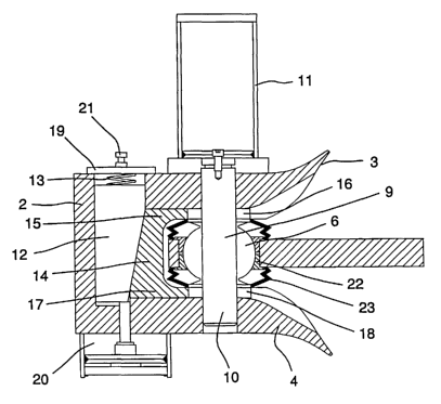
Representative Drawing
A single figure which represents the drawing illustrating the invention.
Administrative Status

For a clearer understanding of the status of the application/patent presented on this page, the site Disclaimer , as well as the definitions for Patent , Administrative Status , Maintenance Fee  and Payment History  should be consulted.

Administrative Status

Title Date
Forecasted Issue Date Unavailable
(86) PCT Filing Date 2001-07-16
(87) PCT Publication Date 2002-01-31
(85) National Entry 2003-01-24
Dead Application 2007-07-16

Abandonment History

Abandonment Date Reason Reinstatement Date
2006-07-17 FAILURE TO REQUEST EXAMINATION
2007-07-16 FAILURE TO PAY APPLICATION MAINTENANCE FEE

Payment History

Fee Type Anniversary Year Due Date Amount Paid Paid Date
Application Fee $150.00 2003-01-24
Maintenance Fee - Application - New Act 2 2003-07-16 $50.00 2003-07-02
Maintenance Fee - Application - New Act 3 2004-07-16 $100.00 2004-07-16
Maintenance Fee - Application - New Act 4 2005-07-18 $100.00 2005-06-22
Maintenance Fee - Application - New Act 5 2006-07-17 $200.00 2006-06-12
Owners on Record

Note: Records showing the ownership history in alphabetical order.

Current Owners on Record
HOLMGREN, SVEN-ERIK
JONSSON, TORD
Past Owners on Record
None
Past Owners that do not appear in the "Owners on Record" listing will appear in other documentation within the application.
Documents

To view selected files, please enter reCAPTCHA code :


To view images, click a link in the Document Description column. To download the documents, select one or more checkboxes in the first column and then click the "Download Selected in PDF format (Zip Archive)" or the "Download Selected as Single PDF" button.

List of published and non-published patent-specific documents on the CPD .

If you have any difficulty accessing content, you can call the Client Service Centre at 1-866-997-1936 or send them an e-mail at CIPO Client Service Centre.


Document
Description 
Date
(yyyy-mm-dd) 
Number of pages   Size of Image (KB) 
Abstract 2003-01-24 1 65
Claims 2003-01-24 1 45
Drawings 2003-01-24 1 32
Description 2003-01-24 2 130
Representative Drawing 2003-01-24 1 17
Cover Page 2003-03-17 1 53
PCT 2003-01-24 7 279
Assignment 2003-01-24 3 82
Fees 2003-07-02 1 29
PCT 2003-01-24 1 41
Fees 2004-07-16 1 32