Note: Descriptions are shown in the official language in which they were submitted.
CA 02417493 2005-04-06
FORCED ENTRY RESISTANCE DEVICE FOR SASH LOCK
DESCRIPTION
Technical Field
This invention relates to sash locks for slidable door or window assemblies.
More
particularly, it relates to a forced entry resistance device for a sash lock.
Backg-round of the Invention
Sash locks for double hung window assemblies are commonly known in the art. A
double hung window assembly generally has an upper sash window and a lower
sash window
within a master frame. Typical sash locks draw opposed frame members of the
sash
windows together and lock the sashes preventing them from sliding within the
master frame.
One problem associated with typical sash locks is their ability to be
manipulated by
an intruder from outside the window assembly. That is, sash locks generally
include some
type of rotatable actuator arm and cam. The actuator is rotatable from an
unlocked to a
locked position. With some sash locks, the actuator arm or cam may be
manipulated from
the outside by a skilled intruder using a thin knife, stiff wire, or other
diabolical tool of
intrusion.
The present invention is provided to solve these and other problems.
SMMMM of the Invention
A sash lock for a sash window assembly is provided. The sash window assembly
includes an upper sash window and a lower sash window, each of the sash
windows mounted
25within opposed guide rails on a master frame, wherein at least one of the
sash windows is
slidable within the frame relative to the other sash window. The sash lock of
the present
invention includes a keeper adapted for mounting on a frame member of one of
the sash
windows. The keeper includes a keeper surface. The sash lock also includes a
locking
assembly adapted for mounting on an adjacent member of the other of the sash
windows.
CA 02417493 2003-01-28
2
The locking assembly comprises a housing having an aperture, an actuator arm
rotatable
between an unlocked position and a locked position and a cam having a cam
surface for
engaging the keeper surface. A shaft is also provided extending through the
aperture and
coupling the actuator arm to the cam such that the actuator arm and cam are
rotatably
mounted to the housing. A tab mounted to the housing is also provided wherein
the tab
engages the actuator arm to retain the actuator in its locked position. The
tab can be
deflected to allow the actuator arm to be moved to its unlocked position.
In an alternative embodiment thetab is integrally formed with the housing.
In an alternative embodiment the tab further comprises a thumb button.
Other features and advantages of the invention will be apparent from the
remainder
of this specification.
Brief Description of the Drawings
FIG. 1 is a perspective view of a sash window assembly;
FIG. 2 is a perspective view of a locking assembly of a prior art sash lock;
FIG. 3 is a perspective view of a forced entry resistance device of the
present
invention;
FIG. 4 is a plan view of the resistance device of the present invention;
FIG. 5 is a side elevation of the resistance device of the present invention;
FIG. 6 is a perspective view of a locking assembly of a sash lock of the
present
invention utilizing the resistance device;
FIG. 7 is a plan view of a locking assembly of the sash lock of the present
invention
utilizing the resistance device;
FIG. 8 is a front elevation of a locking assembly of the sash lock of the
present
invention utilizing the resistance device;
FIG. 9 is a perspective of a locking assembly of the sash lock of the present
invention
with its actuator arm in the locked position;
FIG. 10 is a plan view of the locking assembly of FIG. 9;
FIG.,11 is a front elevation of the locking assembly of FIG. 9;
FIG. 12 is a perspective of an alternative embodiment of a forced entry
resistance
device of the present invention;
CA 02417493 2003-01-28
3
FIG. 13 is a top view of the resistance device of FIG. 12;
FIG. 14 is a front elevation of the resistance device of FIG. 12; and
FIG. 15 is a perspective of a locking assembly of the sash lock including the
alternative embodiment of a resistance device of the present invention, with
its actuator arm
in the locked position.
Detailed Description
While this invention is susceptible.of embodiment in many different forms,
there is
shown in the drawings and will herein be described in detail preferred
embodiments of the
invention with the understanding that the present disclosure is to be
considered as an
exemplification of the principles of the invention and is not intended to
limit the broad aspect
of the invention to the embodiments illustrated.
A sash lock 10 for a sash window assembly 12 is illustrated in the FIGURES. As
generally shown in FIG. 1, the sash window assembly 12 includes an upper sash
window 14
and a lower sash window 16. Each of the sash windows 14, 16 is mounted within
opposed
guide rails 18 on a master frame 20. At least one of the sash windows 14, 16
is slidable
within the frame 20 relative to the other of the sash windows 14, 16. Each
sash window 14,
16 has a pair of horizontal frame members 21.
The sash lock 10 includes a keeper 22 and a locking assembly 24. The keeper 22
2o includes a keeper surface (not shown) and a pair of mount holes (not shown)
for mounting
the keeper 22 to one of the frame members 21, as described more fully below.
The locking assembly 24 of the present invention is shown in FIG. 6 and
includes a
housing 30, an actuator arm 32, a cam 34 (FIG. 10) and a forced entry
resistance device or
anti-rotation device 36. A locking assembly 24 of the prior art without the
anti-rotation
device 36, is shown in FIG. 2. The housing 30 includes a pair of mount holes
28 and an
aperture 33. The cam 34 includes a cam surface 40 (FIG. 10) for engaging the
keeper
surface. A shaft 35 connects the cam 34 to the actuator arm 32 through the
aperture. It is
understood that the actuator arm 32 and the shaft 35 can be a single integral
member. In this
way, the cam 34 and actuator arm 32 are rotatably mounted to the housing 30.
That is, there
is no relative movement between the cam 34 and actuator arm 32, however, the
cam 34 and
actuator arm 32 together, rotate with respect to the housing 30.
CA 02417493 2003-01-28
, 0 .
4
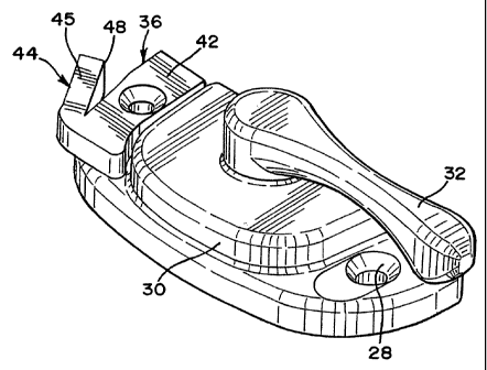
The anti-rotation device 36 (FIGS. 3-8) includes a body 42 having an external
tab 44.
The body 42 is adapted for mounting to the housing 30 and includes a mount
hole 43 for this
purpose. The external tab 44 is generally rectangular in cross section and is
resiliently
flexible. The external tab 44 includes an inclined surface 45 and an
engagement surface 48.
The actuator arm 32 of the locking assembly 24 is rotatable between an
unlocked
position (FIG. 6) and a locked position as shown in FIG. 10. In the unlocked
position, the
cam 34 is located completely within the housing 30. In the locked position,
the cam 34 has
rotated and its cam surface 40 is substantially external to the housing 30 to
engage the keeper
surface.
In the embodiment described, the keeper 22 is mounted to the lower frame
member
or base 21 of the upper sash window 14 (FIG. 1). The keeper 22 is mounted with
a pair of
screws or other fasteners extending through the mount holes and secured to the
base 21.
Typically, the keeper 22 is mounted near the center of the base 21.
The locking assembly 24 is mounted to the upper frame member of top rail 23 of
the
lower sash window 16. It is mounted such that it is immediately adjacent to
the keeper 22
when the upper sash window 14 is in its upper most position within the frame
20 and the
lower sash window 16 is in its lower most position within the frame 20. In
mounting the
locking assembly 24, a screw or other fastener (not shown) is passed through
the mount hole
43 of the body 42 of the anti-rotation device 36. The screw is then passed
through one of
the mount holes 28 of the locking assembly 24 and secured to the top rail 23.
(See FIG. 6).
Another screw or fastener is then used to secure the housing 30 to the top
rail 23 via its other
mount hole 28. In this way, the anti-rotation device 36 is secured to the
housing 30 and the
housing is secured to the upper stile 21 of the lower sash window 16. It is
not important to
which mount hole 28 of the housing 30 the anti-rotation device 36 is secured.
It is important
that the anti-rotation device 36 is in a position to be immediately adjacent
to the actuator arm
32 when the actuator arm 32 is in its locked position.
For instance, the locking assembly 24 depicted in the FIGURES is configured
such
that the actuator arm 32 rotates in a clockwise direction when rotating from
the unlocked to
the locked position. However, it is understood that the locking assembly 24
may be
configured such that its actuator arm 32 rotates in a counter-clockwise
direction in moving
CA 02417493 2003-01-28
' = M 9
from the unlocked to the locked position. In this instance, the device 36
would be mounted
to the other mounting hole 28 of the housing 30 than shown in the FIGURES.
In operation, with the actuator arm 32 in the unlocked position, the upper
sash
window 14 is raised to its upper most position within the frame 20 and the
lower sash
5 window 16 is lowered to its lowermost position within the frame 20. This
brings the locking
assembly 24 to a position immediately adjacent the keeper 22. FIGS. 6-8 show
the locking
assembly 24 with the actuator arm 32 in the unlocked position. The actuator
arm 32 is then
rotated towards it locked position. This rotates the cam 34 to a position
external to the
housing 30 and causes the cam surface 40 to engage the keeper surface, in a
manner
commonly known to those of ordinary skill in the art. As the actuator arm 32
approaches the
locked position, the arm 32 engages the inclined surface 45 of the external
tab 44 slightly
depressing the tab 44. Engagement of actuator arm 32 with the inclined surface
45 of the tab
44 depresses the tab 44 into a deflected position (arrow A in FIGS. 9 and 11).
While the tab
44 is in the deflected position, the actuator arm 32 is allowed to pass by the
tab 44. Once the
actuator arm 32 passes by the tab 44, the tab 44 resiliently snaps back from
its deflected
position to the engagement position wherein the engagement surface 48 of the
tab 44
confronts the actuator arm 32 to prevent rotation of the arm 32 back to its
unlocked position.
While in the engagement position, if the actuator arm 32 is rotated towards
its unlocked
position, the engagement surface 48 will engage the actuator arm 32 preventing
rotation.
FIGS. 9-11 show the locking assembly 24 with the actuator arm 32 in the locked
position.
To rotate the actuator arm 32 back to its unlocked position, the tab 44 must
be
depressed, such as by a user's thumb or other finger. This deflects the tab 44
in the direction
of arrow A and disengages or moves the engagement surface 48 from the
rotational path of
the actuator arm 32 and allows rotation of the same. While the tab 44 is
depressed to a
deflected position, the actuator arm 32 is rotated past the tab 44 to its
unlocked position.
In an additional embodiment of the invention shown in FIGS. 12-15, the anti-
rotation
device 36 includes a thumb button 50. The thumb button 50 is connected at one
end to an
under side of the external tab 44. Another end of the thumb button 50 is
curved and extends
away from the housing 30. The thumb button 50 improves the ease with which a
user may
depress the tab 44 to allow the actuator arm 32 to be moved from the locked to
the unlocked
position.
CA 02417493 2003-01-28
6
Although the invention has been described as being applied to a vertically
sliding
double hung window, it is understood the invention can equally be applied to
horizontally
sliding sash window arrangements orany operable sash window that slides within
a frame.
Additionally, although not shown in the drawings, it will be understood by
those of
ordinary skill in the art, that the anti-rotation device 36 may be integrally
formed with the
housing 30 while remaining within the scope of the present invention.
Furthermore, it is
understood that the resistance or anti-rotation device 36 may be formed from
any number of
materials of sufficient strength to withstand the forces involved in an
attempted rotation of
the actuator arm 32 by an intruder, while remaining resiliently flexible
enough to allow
io depression of the external tab 44 by the user. For example, the device 36
may be formed
from various metals and alloys thereof as commonly known, providing the
required strength
and resilience.
It is also understood that the resistance device 36 may take other forms. For
example,
the device may be a spring biased tab, or pop-up button that similarly
interferes with the path
of rotation of the actuator arm 32 from the locked to the unlocked position.
These
alternatives remain within the scope of this invention.
It can be appreciated that the device 36 of the present invention will prevent
simple
rotation of the actuator arm 32 without additional manipulation of the device
36. The device
36, while not intruder-proof, will provide significant deterrence to forced
entry and unwanted
manipulation of the sash lock 10 from outside the sash window assembly 12. It
can further
be appreciated that as the device 36 is external to the housing 30 of the
locking assembly 24,
an embodiment of the device 36 may be adapted for retrofitting to existing
sash lock 10
installations currently in use. This purpose and others are served by a
simplicity of
construction and an external nature of the device 36, not previously known in
the art.
While the specific embodiments and various details thereof have been
illustrated and
described, numerous modifications come to mind without significantly departing
from the
spirit of the invention and the scope of protection is only limited by the
following claims.