Note: Descriptions are shown in the official language in which they were submitted.
CA 02417510 2003-O1-27
Deck Board Spacing Strap
BACKGROUND OF THE INVENTION
This invention relates to decking tools, and in
particular, to a spacing strap assembly which permits a user
to align, space and hold decking boards in position prior to
nailing.
l0
Outdoor decks and patios have become increasingly popular
in recent years and kits and do-it-yourself books are
available to allow the homeowner as well as the construction
professional to construct elaborate wooden decks and patios.
The aesthetic appearance of the deck is usually judged by the
appearance of the deck boards and their spacing and
appearance. The deck boards are the final item normally
installed after the deck joists have been positioned and
leveled.
Deck boards are typically spaced apart to leave a gap
between adjacent boards so that water can more readily drain
from the deck surfaces. Spacing the boards equally along
support beams and joists, however, has heretofore proven to be
a relatively time consuming and laborious task. Deck boards
are typically positioned, spaced and nailed, one-at-a-time.
Unless the builder is very skilled, it is not unusual for the
deck boards to become gradually out of line, thereby affecting
the overall esthetics of the deck, but also in some cases the
very structure of the deck.
CA 02417510 2003-O1-27
SUMMARY OF THE INVENTION
The present invention provides a deck board spacing
strap. The strap has a series of spacer bars attached thereto
thereby enabling the deck builder to position, space and hold
a substantial number of deck boards in place at one time
before nailing. This enables the builder to review the deck
board configuration before nailing. The present invention
also permits the builder to position out-of-line boards in the
least disruptive manner. With the deck boards assembled,
positioned and properly spaced, nailing time and labor are
substantially reduced.
These together with other objects of the invention, along
with various features of novelty which characterize the
invention, are pointed out with particularity in the claims
annexed hereto and forming a part of this disclosure. For a
better understanding of the invention, its operating
advantages and the specific objects attained by its uses,
reference should be had to the accompanying drawings and
descriptive matter in which there is i:Llustrated a preferred
embodiment of the invention.
BRIEF DESCRIPTION OF THE DRAWINGS
Fig. 1 is a top perspective of view the invention.
Fig. 2 is a close-up, perspective view, partly in section
of the invention.
Fig. 3 is a close-up view of an individual spacer bar.
Fig. 4 is a side view of a double spacer bar assembly
positioned over a first board.
2
CA 02417510 2003-O1-27
Fig. 5 is a side view of the first three spacer bars in
place.
S DETAILED DESCRIPTION OF INVENTION
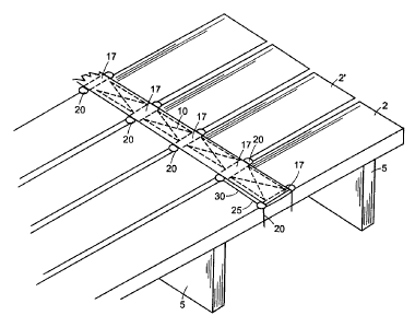
Referring to the drawings in detail wherein like elements
are indicated by like numerals, there is shown an elongated,
generally rectangular spacing strap 10 constructed according
to the principles of the present invention. The spacing strap
10 is constructed with two elongated layers, a top layer 11
and a bottom layer 12. The layers are mirror images of each
other. Each layer 11, 12 is preferably made from a nylon
webbing material. Other materials providing comparable
strength, toughness, durability and longevity may also be
used. The top layer 11 is attached to the bottom layer 12 by
stitching 13. Other means of attachment may also be used.
The spacing strap 10 has two opposing, parallel, elongated
sides 14 defining the strap width. Applicants have found an
approximate width of two to three inches to be preferable.
The spacing strap 10 has two ends, a proximal end 15 and a
distal end 16, said ends defining the general longitudinal
axis of the strap. Beginning at the proximal end 15 the strap
1_ayers form periodic, equidistant, generally cylindrical
interstices 17 between each layer, each interstice having an
elongated central axis transverse to the longitudinal axis of
the spacing strap 10. Each interstice 17 opens out through
both sides 14. In one embodiment of the invention,
specifically adapted to be used with deck boards having an
outside diameter width of five and five-eighths inches, the
interstices 17 are longitudinally positioned six inches apart
on center. In another embodiment of the invention,
specifically adapted to be used with porch boards having an
outside diameter width of three and five-eighths inches, the
3
CA 02417510 2003-O1-27
interstices 17 are longitudinally positioned four inches
apart.
A U-shaped spacer bar 20 is inserted into each interstice
17. Each spacer bar 20 has an elongated, straight,
intermediate, cylindrical portion 21 interconnecting two
opposing, parallel, L- shaped, cylindrical spacer sections 22.
Each spacer section 22 has a nominal diameter of three-
sixteenths inches. Each spacer bar 20 is joined to the
spacing strap 10 so that each spacer bar intermediate portion
21 is held within an interstice 17. The spacer bars 20 are
preferably made from stainless steel. However, the spacer
bars 20 may be made from any other sturdy, weather resistant
material. Spacing cylinders 24 may be slid over the spacer
IS sections 22 (See, Fig. 3) to adjust the radial thickness of
each spacer section 22.
The first two spacer bars 20, beginning with the proximal
strap end 15, are interconnected by two parallel, position
bars 25, resulting in a double spacer bar assembly 30. Each
position bar 25 interconnects the first spacer bar 20 with the
second spacer bar 20. Each position bar 25 has two ends, a
proximal end 26 and a distal end 27. Each position bar
proximal end 26 is attached to the junction 23 of the first
spacer bar intermediate portion 21 and a spacer section 22.
The position bar distal ends 27 are attached to the junctions
23 of the second spacer bar intermediate portion 21 and spacer
sections 22.
In operation, a first deck or porch board 2 is positioned
and aligned as desired. The first board 2 is then attached to
appropriate joists 5 and/or support beams 6. The builder then
fixes the double spacer bar assembly 30 over the first board 2
keeping the remainder of the spacing strap 10 rolled up and
4
CA 02417510 2003-O1-27
positioned over the first board 2 and double spacer bar
assembly 30 as shown in Fig. 4. Each spacer bar 20 is
positioned about a board 2 so that the spacer bar intermediate
portion 21 lies on the top 3 of a particular board 2 and the
bar spacer sections 22 lie along the sides 4 of the board 2.
The builder then assembles a desired number of additional
boards 2' unrolling the spacing strap 10 across the boards 2'
and inserting and positioning the strap spacer bars 20 between
the boards 2, 2', etc. When all the boards are laid down with
deck board spacer bars 20 properly in place, the spacing strap
10 will hold all in position until the builder follows with a
screw gun, hammer, nail gun, or the like, securing all boards
to the appropriate joists 5 and/or support beams 6. Typically
two straps 10 would be used, however, any number of straps 10
may be used as desired. Separation between boards 2 may be
adjusted by means of spacing cylinders 24 slid over the spacer
bar spacer sections 22.
It is understood that the above-described embodiment is
rnerely illustrative of the application. Other embodiments may
be readily devised by those skilled in the art which will
embody the principles of the invention and fall within the
spirit and scope thereof. Space bars 20 may be made in
different sizes and thicknesses. Spacing cylinders 24 may
also be provided in different sizes and thicknesses.
5