Language selection

Search

Patent 2418020 Summary

Third-party information liability

Some of the information on this Web page has been provided by external sources. The Government of Canada is not responsible for the accuracy, reliability or currency of the information supplied by external sources. Users wishing to rely upon this information should consult directly with the source of the information. Content provided by external sources is not subject to official languages, privacy and accessibility requirements.

Claims and Abstract availability

Any discrepancies in the text and image of the Claims and Abstract are due to differing posting times. Text of the Claims and Abstract are posted:

  • At the time the application is open to public inspection;
  • At the time of issue of the patent (grant).
(12) Patent: (11) CA 2418020
(54) English Title: STEEL SLAG PROCESSING JIG SYSTEM
(54) French Title: SYSTEME DE BAC A PISTONNAGE POUR LE TRAITEMENT DE RESIDUS D'ACIER
Status: Deemed expired
Bibliographic Data
(51) International Patent Classification (IPC):
  • C21B 3/04 (2006.01)
  • B02C 17/00 (2006.01)
  • B03B 5/10 (2006.01)
  • B03B 5/48 (2006.01)
  • B03B 9/04 (2006.01)
  • B03C 1/00 (2006.01)
(72) Inventors :
  • BRODEUR, JEAN (Canada)
(73) Owners :
  • TROCAN INC. (Not Available)
(71) Applicants :
  • BRODEUR, JEAN (Canada)
(74) Agent: GOWLING WLG (CANADA) LLP
(74) Associate agent:
(45) Issued: 2011-09-13
(22) Filed Date: 2003-02-04
(41) Open to Public Inspection: 2004-08-04
Examination requested: 2008-02-04
Availability of licence: N/A
(25) Language of filing: English

Patent Cooperation Treaty (PCT): No

(30) Application Priority Data: None

Abstracts

English Abstract


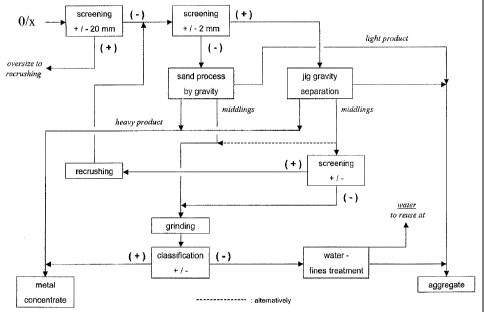
The present invention relates to a method for separating steel slag into a
metal
concentrate fraction and an aggregate fraction by (i) crushing the slag and
screening to
recover slag having a diameter of less than about 20 mm and (ii) further
separating the
recovered slag in a first fraction of more than about 2 mm and a second
fraction of less
than about 2 mm. The first fraction is separated into a metal concentrate
fraction, an
aggregate fraction a coarse middlings fraction and a fine middlings fraction.
The second
fraction is separated into a metal concentrate fraction, an aggregate
fraction, and a
middlings fraction. The coarse middlings of the first fraction are recrushed
and fed into
step ii), whereas the middlings from the second fraction and the fine
middlings from the
first fraction are ground and separated into a metal concentrate fraction and
an
aggregate fraction.


French Abstract

La présente invention se rapporte à une méthode de séparation des scories de l'acier en une fraction de concentré de métal et en une fraction d'agrégat. Voici le mode opératoire. i) Broyage des scories et criblage pour récupérer les scories dont le diamètre est inférieur à environ 20 mm; et ii) séparation ultérieure des scories récupérées d'une première fraction, de plus de 2 mm et d'une seconde fraction, de moins de 2 mm. La première fraction est séparée en une fraction de concentré de métal, une fraction d'agrégat, une fraction moyenne brute et une faction moyenne fine. La seconde fraction est séparée en une fraction de concentré de métal, une fraction d'agrégat et une fraction moyenne. La fraction moyenne brute de la première fraction est broyée de nouveau et appliquée selon l'étape ii), tandis que la fraction moyenne de la seconde fraction et de la fraction moyenne fine provenant de la première fraction est moulue et séparée en une fraction de concentré de métal et en une fraction d'agrégat.

Claims

Note: Claims are shown in the official language in which they were submitted.


6

CLAIMS


The embodiments of the invention in which an exclusive property or privilege
is claimed
are defined as follows:


1. A method of separating steel slag into a metal fraction and an aggregate
fraction
comprising the steps of:

i) crushing said slag and subjecting it to screening and recovering slag
having a
diameter of less than about 20 mm;

ii) separating said recovered slag into a first fraction having a diameter of
more than
about 2 mm and a-second fraction having a diameter of less than about 2 mm;

iii) feeding the said first fraction into a jig, wherein said jig separates
the said first
fraction into a metal concentrate fraction, a middlings fraction and an
aggregate
fraction;

iv) separating the middlings fraction into a coarse middlings fraction and a
fine
middlings fraction;

v) separating said second fraction into a metal concentrate fraction, a
middlings
fraction and an aggregate fraction; and

vi) recrushing the coarse middlings from the first fraction and feeding into
step ii);
wherein the middlings from the second fraction and the fine middlings from the
first
fraction are ground and separated into a metal concentrate fraction and an
aggregate
fraction.

2. The method of claim 1 wherein the steel slag is carbon steel slag or
stainless steel slag.
3. The method of claim 1 wherein in step (i), the slag is sized by means of
one or
more screens and separated by magnetic separators, eddy current separators,
inductive
separators or air jigging

4. The method of claim 3 wherein the magnetic separator is low intensity.


7

5. The method of claim 3 wherein the magnetic separator is high intensity.

6. The method of claim 1 wherein the separation of the second fraction is
carried out using
one or more of an up-current separator, spiral separator, fine jigging,
shaking table or
magnets.

7. The method of claim 1 wherein more than 95% of the metal in the slag is
recovered.
8. The method of claim 7 wherein more than 97% of the metal in the slag is
recovered.

9. The method of claim 1 wherein the aggregate fraction comprises less than
about 0.3%
metal.

10. The method of claim 1 wherein the aggregate fraction comprises less than
about 0.3%
metal.

Description

Note: Descriptions are shown in the official language in which they were submitted.


CA 02418020 2010-04-30

1
STEEL SLAG PROCESSING JIG SYSTEM

FIELD OF THE INVENTION

The present invention concerns the processing of steel slag through a jigging
system to
recover the metallic fraction without changing the physical properties of both
the metallic
concentrate and the residual aggregate.

BACKGROUND OF THE INVENTION

Steel production generates a residue called slag. This by-product is formed.
by the
additives added during melting such as lime, flux, etc, impurities from the
raw material and a
limited quantity of metal entrenched in the slag.

Processing of steel production residues is requested to avoid stockpiling and
further
environmental problems. The feasibility of treating the slag depends on the
metal content In the
slag, the cost of recovering as much metal as possible and on capacity to
dispose the residual
aggregate in a profitable way.

As more and more steel is produced from scrap, metal recovered from slag
becomes a
valuable source of raw material for the steel producers. Existing technologies
for recovery
involve screening and magnetic separation or fine grinding and recovery
through physical
separation.

Recovery through magnetic means is a simple and inexpensive process which also
allows for use of the residual product as an aggregate in civil works.
However, the rate of
recovery is low: the metal content in the recovered concentrate (<20mm)
averages 50% and the
aggregate's quality is not according to established standards.

The wet grinding process allows an higher rate of recovery (almost 99.5%) of
the metal in
the slag. The metallic concentrate yield is generally around 90 to 92%. But it
produces a very
fine wet aggregate. It is an expensive process because 100% of the slag needs
to be crushed to


CA 02418020 2010-04-30

2
a diameter of less than 6mm. Secondly the disposal of the final aggregate is
limited because it
is wet and also because it is a very fine product.

Therefore, there exists a need in slag processing to recover as much metal as
possible
by keeping the physical characteristics of the aggregate, which allows for
easy disposal and
commercialisation.

Jigging systems are well known to separate higher density from lower density
material.
Coal preparation, ore beneficiation and sometimes recycling of valuable
material do often have a
jigging process as a separation step in their flow sheet. Furthermore, the
jigging system can be
combined with a wide range of other separation processes for this special
application.

The main object of this invention is to maximize metal recovery and to produce
an easily
marketable aggregate, at a competitive cost per ton of product treated.

SUMMARY OF THE INVENTION

The invention is based on crushing the slag to size corresponding to general
use for civil
works (less than 20 mm). Then the slag is split into two fractions: less than
2 mm and 2 to 20
mm.

The fraction 2 to 20 mm is fed to a jigging system. The system is designed
with one
discharge gate for metallic concentrate removal and one for removal of the
middlings. The
residual aggregate is evacuated at the end of the jig as the light product.

The fraction of less than 2 mm is fed to a fines leaning stage which includes
a
concentrating step, a ball-mill and two dewatering screws.

This concentration step can be a gravity and/or a magnetic separation process.
Up-
current separators, spiral separators, conventional fine or centrifugal fine
jigging, shaking tables,
low and high grade magnets can be used.

The result of the process is a clean metal (more than 95% metal content in the
fraction of
<20 mm), a clean aggregate with a very low metallic content in the fraction
1,5 to 20 mm and a


CA 02418020 2011-02-03

3
sand <2 mm. The metal is returned to steel production and the aggregate can be
marketed as
a road stone for civil works.

BRIEF DESCRIPTION OF THE DRAWINGS

Figure 1 is a process flow chart outlining the process of the invention;

Figure 2 is a process flow chart of the dry separation steps of the process of
the
invention; and

Figure 3 is a process flow chart of the wet separation steps of the process of
the
invention.

DESCRIPTION OF PREFERRED EMBODIMENTS

The following detailed description, given by way of example and not Intended
to limit the
present invention solely thereto, is best understood in conjunction with the
accompanying
drawings.

The preferred embodiment of the present invention is similar to the process
described In
figures 1, 2 and 3, which includes five different stages:

Pre-screening and classifying

The raw slag is crushed in several stages in a product having a diameter of
less than 20
mm. Depending on the intergrowth of the slag and metal, the raw slag must be
crushed to a
diameter of less than 10 mm. Various known techniques like selective impact
crushing,
screening, magnetic separation, eddy current and inductive separation as well
as air jigging can

prepare the feed for the wet separation process by separating pre-concentrates
or even free
metal (figure 2)

The slag Is classified into two fractions: diameter of less than 2 mm and
diameter of 2 to 20 mm.
The slag is fed in a feed bin and transported by conveyor to a wet preparation
screen.

Separation of the + 2 mm fraction

The 2 to 20 mm fraction is fed into the jig where it will be separated in
three products, a
metal concentrate, the middlings and the aggregate. The metal concentrate
represents the final


CA 02418020 2010-04-30

4
product. The middlings are returned to the crusher to liberate the metal. The
aggregate is a
marketable product for civil works.

Separation of the -2 mm fraction

The fines fraction is forwarded to a cyclone and from the cyclone it either
goes to the
grinding step directly or it will enter the gravity process for the sand
fraction of the slag. Up-
current separators, spiral separators, fine jigging, shaking tables, and/or
low and high grade
magnets are alternatively used for the further enrichment of the metal and the
middlings. A light
product is separated as a clean slag and can be used as a sand aggregate. The
fine metal
product is combined with the concentrate from the coarse jig. By this
additional gravity process

only the middlings will go to the grinding process to get the remaining metal
liberated. Figure 3
shows an alternative for the processing of the sand fraction in two separate
density processes,
one for the coarse and the other for the fine sand. This process can be
necessary, if the
material is very finely intergrown and the crushing must go down to e.g. 10 mm
for the wet
process.

Grinding and separation of fines and middlings

The middlings produced in the gravity section for fines or alternatively all
fines are
forwarded to a screw classifier and then to a ball-mill for a selective
grinding step. The product
from the ball-mill is then washed and dewatered by two screw classifiers.

Thickening, dewatering, and water recycling

All the non-metallic fines of a diameter of less than 2 mm are sent to the
fines treatment
and water recovery circuit. The slimes are clarified in a thickener. The
thickener undertow with
all the slimes with high solid contents is dewatered in a vacuum filter. The
thickener overflow
feeds a process water tank. Loss of water in the plant is equalized by fresh
water.

Although the invention has been described above with respect to specific
embodiments,
it will be evident to a person skilled in the art that it may be modified and
refined in various


CA 02418020 2004-02-03

ways. It is therefore wished to have it understood that the present invention
should not be
limited in scope, except by the terms of the following claims.

5
15
25

Representative Drawing
A single figure which represents the drawing illustrating the invention.
Administrative Status

For a clearer understanding of the status of the application/patent presented on this page, the site Disclaimer , as well as the definitions for Patent , Administrative Status , Maintenance Fee  and Payment History  should be consulted.

Administrative Status

Title Date
Forecasted Issue Date 2011-09-13
(22) Filed 2003-02-04
(41) Open to Public Inspection 2004-08-04
Examination Requested 2008-02-04
(45) Issued 2011-09-13
Deemed Expired 2020-02-04

Abandonment History

There is no abandonment history.

Payment History

Fee Type Anniversary Year Due Date Amount Paid Paid Date
Application Fee $150.00 2003-02-04
Registration of a document - section 124 $100.00 2003-10-31
Maintenance Fee - Application - New Act 2 2005-02-04 $50.00 2005-01-21
Maintenance Fee - Application - New Act 3 2006-02-06 $50.00 2005-11-29
Maintenance Fee - Application - New Act 4 2007-02-05 $50.00 2007-01-09
Maintenance Fee - Application - New Act 5 2008-02-04 $100.00 2008-01-29
Request for Examination $400.00 2008-02-04
Maintenance Fee - Application - New Act 6 2009-02-04 $100.00 2009-02-03
Maintenance Fee - Application - New Act 7 2010-02-04 $100.00 2010-01-27
Maintenance Fee - Application - New Act 8 2011-02-04 $100.00 2011-02-01
Final Fee $150.00 2011-06-27
Maintenance Fee - Patent - New Act 9 2012-02-06 $100.00 2012-01-24
Maintenance Fee - Patent - New Act 10 2013-02-04 $125.00 2012-12-03
Maintenance Fee - Patent - New Act 11 2014-02-04 $125.00 2014-01-07
Maintenance Fee - Patent - New Act 12 2015-02-04 $125.00 2014-11-26
Maintenance Fee - Patent - New Act 13 2016-02-04 $125.00 2015-11-10
Maintenance Fee - Patent - New Act 14 2017-02-06 $125.00 2016-11-14
Maintenance Fee - Patent - New Act 15 2018-02-05 $225.00 2018-01-15
Owners on Record

Note: Records showing the ownership history in alphabetical order.

Current Owners on Record
TROCAN INC.
Past Owners on Record
BRODEUR, JEAN
Past Owners that do not appear in the "Owners on Record" listing will appear in other documentation within the application.
Documents

To view selected files, please enter reCAPTCHA code :


To view images, click a link in the Document Description column. To download the documents, select one or more checkboxes in the first column and then click the "Download Selected in PDF format (Zip Archive)" or the "Download Selected as Single PDF" button.

List of published and non-published patent-specific documents on the CPD .

If you have any difficulty accessing content, you can call the Client Service Centre at 1-866-997-1936 or send them an e-mail at CIPO Client Service Centre.


Document
Description 
Date
(yyyy-mm-dd) 
Number of pages   Size of Image (KB) 
Abstract 2011-02-03 1 20
Description 2011-02-03 5 174
Claims 2011-02-03 2 52
Description 2003-02-04 7 245
Claims 2003-02-04 1 10
Drawings 2003-02-04 3 97
Representative Drawing 2003-04-03 1 12
Description 2004-02-03 5 171
Abstract 2004-02-11 1 7
Claims 2004-02-03 2 42
Cover Page 2004-07-09 1 31
Representative Drawing 2011-08-08 1 12
Cover Page 2011-08-08 2 48
Abstract 2010-04-30 1 21
Description 2010-04-30 5 177
Claims 2010-04-30 2 51
Correspondence 2003-03-04 1 18
Assignment 2003-02-04 2 48
Correspondence 2004-02-02 2 43
Assignment 2003-10-31 2 47
Correspondence 2004-02-11 3 67
Prosecution-Amendment 2004-02-03 8 240
Assignment 2003-02-04 5 121
Fees 2011-02-01 1 40
Fees 2005-01-21 1 32
Fees 2005-11-29 1 36
Fees 2007-01-09 1 39
Fees 2008-01-29 2 77
Correspondence 2008-01-29 2 77
Prosecution-Amendment 2008-02-04 1 40
Fees 2009-02-03 1 42
Prosecution-Amendment 2009-11-19 2 75
Fees 2010-01-27 1 40
Prosecution-Amendment 2010-04-30 14 537
Prosecution-Amendment 2010-08-19 2 51
Prosecution-Amendment 2011-02-03 6 225
Correspondence 2011-06-27 2 46