Note: Descriptions are shown in the official language in which they were submitted.
CA 02418089 2003-02-04
WO 02/13143 PCT/AU01/00946
1
IMAGE CONVERSION AND ENCODING TECHNIC~UE
Field of Invention
The present invention is directed towards a technique for converting 2D
images into 3D, and in particular a method for converting 2D images which have
been formed from a layered source.
Background
The limitation of bandwidth on transmissions is a well known problem, and
many techniques have been attempted to enable the maximum amount of data to
be transferred in the shortest time possible. The demands on bandwidth are
particularly evident in the transmission of images, including computer
generated
images.
One attempt to address bandwidth and performance issues with computer
generated images or animated scenes has been to only transfer changes in the
image once the original scene has been transmitted. This technique takes
advantage of the way in which cartoons have traditionally been created. That
is,
a cartoonist may create the perception of movement by creating a series of
stills
which contain all the intermediary steps which make up the movement to be
created.
For simplicity and ease of amendment each object in an image will usually
be created on a separate layer, and the layers combined to form the image.
That
is, a moving object would be drawn on a series of sheets so as to demonstrate
movement of that object. However, no other objects or background would usually
be drawn on that sheet. Rather, the background, which does not change, would
be drawn on a separate sheet, and the sheets combined to create the image.
Obviously, in some cases many sheets may be used to create a single still.
For cartoons or animated images which have been created using a series
of different layers it is possible to save on data transmission by only
transmitting
those layers which have been altered. For example, if the background has not
been changed there is no need to retransmit the background layer. Rather, the
display medium can be told to maintain the existing background layer.
Along with the increase in the use of animated or computer generated
images, there has also been an increase in the demand for stereoscopic images.
CA 02418089 2003-02-04
WO 02/13143 PCT/AU01/00946
2
The creation of stereoscopic images (at the filming stage) whilst viable, is
significantly more costly, difficult and time consuming than 2D. Accordingly,
the
amount of stereo content in existence is lacking, and therefore there is a
demand
to be able to convert existing 2D images into 3D images.
Early attempts to convert 2D images into 3D images involved selecting an
object within an image, and cutting and pasting that object in another
location so
as to create the effect of 3D. However, it was quickly discovered that this
technique was unacceptable to either the public or the industry, as the
technique
by virtue of the cutting and pasting created "cut-out" areas in the image.
That is,
by cutting and moving objects, void areas without image data were created.
In order to provide a system to convert 2D images into 3D images, the
present Applicants created a system whereby stereoscopic images are created
from an original 2D image by:
a. identifying at least one object within the original image;
b. outlining each object;
c. defining a depth characteristic for each object; and
d. respectively displacing selected areas of each object by a
determined amount in a lateral direction as a function of the depth
characteristic
of each object, to form two stretched images for viewing by the left and right
eyes
of the viewer.
This system disclosed in PCT/AU96/00820, the contents of which are
incorporated herein by reference, avoided the creation of cut-out areas by
stretching or distorting objects within the original image. That is, this
prior system
did not create the unacceptable problem of cut outs which simply moving an
object creates.
Whilst the Applicants prior system may be utilised to convert 2D cartoons
or animations, it is not ideal in some circumstances. For example, if a
display
system only receives alterations to the 2D image as opposed to the whole 2D
image, the Applicants prior system would need to recreate the image so as to
carry out the steps outlined above.
CA 02418089 2003-02-04
WO 02/13143 PCT/AU01/00946
3
Objective of the Invention
It is therefore an objective of the present invention to provide an improved
2D to 3D conversion process which is applicable for use with layered 2D images
such as cartoons, animations or other computer generated images, and including
images created from a segmented source.
Summary of the Invention
With the above object in mind, the present invention provides in one
aspect a method of producing left and right eye images for a stereoscopic
display
from a layered source including at least one layer, and at least one object on
said
at least one layer, including the steps of:
defining a depth characteristic for each object or layer, and
respectively displacing each object or layer by a determined amount in a
lateral direction as a function of the depth characteristic of each layer.
The system may be modified to further segment objects into additional
layers, and ideally the displaced objects would be further processed by
stretching
or distorting the image to enhance the 3D image.
The stored parameters for each object may be modified, for example an
additional tag may be added which defines the depth characteristics. In such
systems the tag information may also be used to assist in shifting the
objects.
In order for the image to be compatible with existing 2D systems it may be
desirable to process the 2D image at the transmission end, as opposed to the
receiving end, and embed the information defining the depth characteristic for
each object or layer in the 2D image, such that the receiver can then either
display the original 2D image or alternatively the converted 3D image.
This system allows animated images and images generated from a
layered source to be effectively and efficiently converted for viewing in 3D.
The
additional data which is added to the image is relatively small compared with
the
size of the 2D image, yet enables the receiving end to project a 3D
representation of the 2D image. In the preferred arrangement the system would
ideally also allow the viewer to have some control over the 3D
characteristics,
such as strength and depth sensation etc.
CA 02418089 2003-02-04
WO 02/13143 PCT/AU01/00946
4
Brief Description of the Drawings
To provide a better understanding of the present invention, reference is
made to the accompanying drawings, which illustrate a preferred embodiment of
the present invention.
In the Drawings
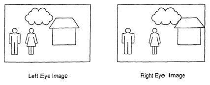
Figure 1 shows an example composite layered 2D image.
Figure 2 shows how the composite image in Figure 1 may be composed of
objects existing on separate layers.
Figure 3 shows how left and right eye images are formed.
Figure 4 shows a flow diagram of the process of the preferred embodiment
of the present invention.
Detailed Description of the Invention
In the preferred embodiment, the conversion technique includes the
following steps:
IDENTIFY EACH OBJECT ON EACH LAYER AND ASSIGN A DEPTH
CHARACTERISTIC TO EACH OBJECT
The process to be described is intended to be applied to 2D images that
are derived from a layered source. Such images include, but are not limited
to,
cartoons, MPEG video sequences (in particular video images processed using
MPEG4 where each object has been assigned a Video Object Plane) and
Multimedia images intended for transmission via the Internet, for example
images
presented in Macromedia "Flash" format.
In such formats, the original objects on each layer may be vector
representations of each object, and have tags associated with them. These tags
may describe the properties of each object, for example, colour, position and
textu re.
Such an example layered 2D image is shown in Figure 1. Figure 2
illustrates how the composite image in Figure 1 can be composed of objects
existing on separate layers and consolidated so as to form a single image. It
will
be appreciated by those skilled in the art that the separate layers forming
the
composite image may also be represented in a digital or video format. In
particular it should be noted that the objects on such layers may be
represented
CA 02418089 2003-02-04
WO 02/13143 PCT/AU01/00946
in a vector format. When necessary, objects in each layer of the 2D image to
be
converted may be identified by a human operator using visual inspection. The
operator will typically tag each object, or group of objects, in the image
using a
computer mouse, light pen, stylus or other device and assign a unique number
to
5 the object. The number may be manually created by the operator or
automatically
generated in a particular sequence by a computer.
An operator may also use object identification information produced by
another operator either working on the same sequence or from prior conversion
of similar scenes.
Where more than one object is present on a specific layer it may be
desirable to further segment the objects into additional layers to enhance the
3D
effect. This is the case where a layer has multiple objects, and it is desired
to
have those objects at different depths. That is, if you have multiple objects
on a
single layer, and each needed to be at a different depth, then you would sub-
segment the layer into one or more objects and/or layers.
In the preferred embodiment, each layer, and object within the layer, is
assigned an identifier. In addition, each object is assigned a depth
characteristic
in the manner previously disclosed in application PCT/AU98/01005 that is
hereby
included by reference.
For vector representation an additional tag could be added to the vector
representation to describe the object depth. The description could be some x
meters away or have some complex depth, such as a linear ramp.
It should be noted that the tag describing the object depth need not
describe the depth directly but represent some function of depth. Those
skilled in
the art would appreciate that such representations include; but are not
limited to
disparity and pull maps.
The depth of an object or objects may be determined either manually,
automatically or semi-automatically. The depth of the objects may be assigned
using any alphanumeric, visual, audible or tactile information. In another
embodiment the depth of the object may be assigned a numerical value. This
value may be positive or negative, in a linear or non-linear series and
contain
CA 02418089 2003-02-04
WO 02/13143 PCT/AU01/00946
6
single or multiple digits. In a preferred embodiment this value will range
from 0 to
255, to enable the value to be encoded in a single byte, where 255 represents
objects that are to appear, once converted, at a 3D position closest to the
viewer
and 0 for objects that are at the furthest 3D distance from the viewer.
Obviously
this convention may be altered, eg reversed or another range used.
In manual depth definition the operator may assign the depth of the object
or objects using a computer mouse, light pen, stylus or other device. The
operator may assign the depth of the object by placing the pointing device
within
the object outline and entering a depth value. The depth may be entered by the
operator as a numeric, alphanumeric or graphical value and may be assigned by
the operator or automatically assigned by the computer from a predetermined
range of allowable values. The operator may also select the object depth from
a
library or menu of allowable depths.
The operator may also assign a range of depths within an object or a
depth range that varies with time, object location or motion or any
combination of
these factors. For example the object may be a table that ideally has its
closest
edge towards the viewer and its farthest edge away from the viewer. When
converted into 3D the apparent depth of the table must vary along its length.
In
order to achieve this the operator may divide the table up into a number of
segments or layers and assign each segment an individual depth. Alternatively
the operator may assign a continuously variable depth within the object by
shading the object such that the amount of shading represents the depth at
that
particular position of the table. In this example a light shading could
represent a
close object and dark shading a distant object. For the example of the table,
the
closest edge would be shaded lightly, with the shading getting progressively
darker, until the furthest edge is reached.
The variation of depth within an object may be linear or non-linear and
may vary with time, object location or motion or any combination of these
factors.
The variation of depth within an object may be in the form of a ramp. A
linear ramp would have a start point (A) and an end point (B). The colour at
point
A and B is defined. A gradient from Point A to Point B is applied on the
CA 02418089 2003-02-04
WO 02/13143 PCT/AU01/00946
7
perpendicular line.
A Radial Ramp defines a similar ramp to a linear ramp although it uses the
distance from a centre point (A) to a radius (B). For example, the radial
depth
may be represented as:
x, y, r, d1, d2, fn
where x and y are the coordinates of the centre point of the radius, d1 is
the depth at the centre, d2 is the depth at the radius and fn is a function
that
describes how the depth varies from d1 to d2, for example linear, quadratic
etc.
A simple extension to the Radial Ramp would be to taper the outside rim,
or to allow a variable sized centre point.
A Linear Extension is the distance from a line segment as opposed to the
distance from the perpendicular. In this example the colour is defined for the
line
segment, and the colour for the "outside". The colour along the line segment
is
defined, and the colour tapers out to the "outside" colour.
A variety of ramps can be easily encoded. Ramps may also be based on
more complex curves, equations, variable transparency etc.
In another example an object may move from the front of the image to the
rear over a period of frames. The operator could assign a depth for the object
in
the first frame and depth of the object in the last or subsequent scene. The
computer may then interpolate the depth of the object over successive frames
in
a linear or other predetermined manner. This process may also be fully
automated whereby a computer assigns the variation in object depth based upon
the change in size of an object as it moves over time.
Once an object has been assigned a specific depth the object may then be
tracked either manually, automatically or semi-automatically as it moves
within
the image over successive frames. For example, if an object was moving or
shifting though an image over time, we could monitor this movement using the
vector representations of the object. That is, we could monitor the size of
the
vectors over time and determine if the object was getting larger or smaller.
Generally speaking if the object is getting larger then it is probably getting
closer
to the viewer and vise versa. In many cases the object will be the only object
on
CA 02418089 2003-02-04
WO 02/13143 PCT/AU01/00946
a particular layer.
An operator may also use depth definitions produced by another operator
either working on the same sequence or from prior conversion of similar
scenes.
In order to produce more realistic looking 3D it is sometimes desirable to
utilise depth definitions that are more complex than simple ramps or linear
variations. This is particularly desirable for objects that have a complex
internal
structure with many variations in depth, for example, a tree. The depth map
for
such objects could be produced by adding a texture bump map to the object. For
example, if we consider a tree, we would firstly assign the tree a depth. Then
a
texture bump map could be added to give each leaf on the tree its own
individual
depth. Such texture maps have been found useful to the present invention for
adding detail to relatively simple objects.
However, for fine detail, such as the leaves on a tree or other complex
objects, this method is not preferred, as the method would be further
complicated
should the tree, or the like, move in the wind or the camera angle change from
frame to frame. A further and more preferred method is to use the luminance
(or
black and white components) of the original object to create the
necessary.bump
map. In general, elements of the object that are closer to the viewer will be
lighter and those further away darker. Thus by assigning a light luminance
value
to close elements and dark luminance to distant elements a bump map can be
automatically created. The advantage of this technique is that the object
itself
can be used to create its own bump map and any movement of the object from
frame to frame is automatically tracked. Other attributes of an object may
also be
used to create a bump map, these include but are not limited to, chrominance,
saturation, colour grouping, reflections, shadows, focus, sharpness etc.
The bump map values obtained from the object attributes will also
preferably be scaled so the that the range of depth variation within the
object are
consistent with the general range of depths of the overall image.
Each layer, and each object is assigned an identifier, and further each
object is assigned a depth characteristic. The general format of the object
definition is therefore:
CA 02418089 2003-02-04
WO 02/13143 PCT/AU01/00946
9
<layer identifier><object identifier><depth characteristic>
where each identifier can be any alphanumeric identifier and the depth
characteristic is as previously disclosed. It should be noted that the depth
characteristic may include alphanumeric representations of the object's depth.
The present invention discloses the addition of a depth characteristic
identifier to existing layer based image storage and transmission protocols
that
may already identify objects within an image by other means.
In the simplest implementation the layer identifier may be used as a direct,
or referred, reference to the object depth.
For example purposes only, consider a 2D image consisting of 4 layers
with each layer containing a single object. The layers may be numbered 1 to 4
and ordered such that, when displayed stereoscopically, the object on layer 1
appears closest to the viewer, the object on layer 2 appears behind the object
on
layer 1 etc, such that the object on layer 4 appears furthest from the viewer.
It
will be obvious to those skilled in the art that this sequence could be
reversed i.e.
layer 4 could contain an object that is closer to the viewer and layer 1 an
object
furthest from the viewer or a non sequential depth or non linear
representations
applied.
This technique of allocating the layer number as the depth value, is suited
for relatively simple images where the number of objects, layers and relative
depths does not change over the duration of the image.
However, this embodiment has the disadvantage that should additional
layers be introduced or removed during the 2D sequence then the overall depth
of the image may vary between scenes. Accordingly, the general form of the
object definition overcomes this limitation by separating the identifiers
relating to
object depth and layer.
LATERALLY DISPLACE EACH LAYER
For purpose of explanation only it is assumed that the 2D image is
composed of a number of objects that exist on separate layers. It is also
assumed that the 2D image is to be converted to 3D and displayed on a
stereoscopic display that requires separate left and right eye images. The
layers
CA 02418089 2003-02-04
WO 02/13143 PCT/AU01/00946
are sequenced such that the object on layer 1 is required to be seen closest
to
the viewer when converted into a stereoscopic image and the object on layer n
furthest from the viewer.
For purpose of explanation only, it is also assumed that the object depth is
5 equal to, or a function of, the layer number. It is also assumed that the
nearest
object i.e. layer 1, will have zero parallax on the stereoscopic viewing
device such
that the object appears on the surface of the display device, and that all
other
objects on sequential layers will appear behind successive objects.
In order to produce the left eye image sequence a copy of layer 1 of the
10 2D image is made. A copy of layer 2 is then made and placed below layer 1
with
a lateral shift to the left. The amount of lateral shift is determined so as
to
produce an aesthetically pleasing stereoscopic effect or in compliance with
some
previously agreed standard, convention or instruction. Copies of subsequent
layers are made in a similar manner, each with the same lateral shift as the
previous layer or an increasing lateral shift as each layer is added. The
amount
of lateral shift will determine how tar the object is from the viewer. The
object
identification indicates which object to shift and the assigned depth
indicates by
how much.
In order to produce the right eye image sequence a copy of layer 1 of the
2D image is made. A copy of layer 2 is then made and placed below layer 1 with
a lateral shift to the right. In the preferred embodiment the lateral shift is
equal
and opposite to that used in the left eye. For example, should layer 2 be
shifted
to the left by -2 mm then for the right eye a shift of +2 mm would be used. It
should be appreciated that the unit of shift measurement will relate to the
medium
the 2D image is represented in and may include, although not limited to,
pixels,
percentage of image size, percentage of screen size etc.
A composite image is then created from the separate layers so as to form
separate left and right eye images that may subsequently be viewed as a stereo
pair. This is illustrated in Figure 3.
In the preceding explanation it is possible that the original layered image
may be used to create one eye view as an alternative to making a copy. That
is,
CA 02418089 2003-02-04
WO 02/13143 PCT/AU01/00946
11
the original image may become the right eye image, and the left eye image may
be created by displacing the respective layers.
It will be understood by those skilled in the art that this technique could be
applied to a sequence of images and for explanation purposes only a single 2D
image has been illustrated.
It will also be understood by those skilled in the art that the objects in the
original 2D image may be described in other than visible images, for example
vector based representations of objects. It is a specific objective of this
invention
that it be applicable to all image formats that are composed of layers. This
includes, but is not limited to, cartoons, vector based images i.e. Macromedia
Flash, MPEG encoded images (in particular MPEG 4 and MPEG 7 format
images) and sprite based images.
Referring now to figure 4 there is shown a flow diagram of the preferred
embodiment of the present invention. After receiving an image from a layered
source, the system selects the first layer of the source material. It will be
understood, that whilst an object may be located on a separate layer in some
instances multiple objects may be located on the same layer. For example a
layer which serves merely as a background may in fact have a number of objects
located on that layer. Accordingly, the layer is analyzed to determine whether
or
not a plurality of objects are present on that layer.
If the layer does have multiple objects, then it is necessary to determine
whether each of those objects on that layer are to appear at the same depth as
each other object on that layer. If it is desired that at least one of the
objects on
the layer appears at a different depth to another object on that same layer
then a
new layer should be created for this object. Similarly, if a number of the
objects
on a single layer are each to appear at different depths, then a layer for
each
depth should be created. In this way a layer will only contain a single
object, or
multiple objects which are to appear at the same depth.
Once a single object layer, or a layer with multiple objects which are to
appear at the same depth has been determined, and it is necessary to assign a
depth to those objects. This depth may be assigned manually by an operator or
CA 02418089 2003-02-04
WO 02/13143 PCT/AU01/00946
12
by some other means such as predefined rule set. Once the objects on the layer
have been assigned a depth characteristic, it is necessary to then modify the
objects and/or layers to create a stereoscopic image.
The stereoscopic image will include both a left eye image and a right eye
image. The system may conveniently create the left eye image first by
laterally
shifting the layer as a function of the depth characteristic. Alternatively,
for
electronic versions of the image, it may be simpler to laterally shift the
object or
objects that is on the layer. For example, considering an electronic version
such
as Flash, then the object could be shifted by adjusting the tags associated
with
that object. That is, one of the object tags would be the x, y coordinate.
This
system may be configured to modify these x, y coordinates as a function of the
depth characteristic of the object so as to laterally shift the object. By
laterally
shifting the object and/or layer, the left eye image may be created.
In order to create the right eye image a new layer is created, and the
original object and/or layer, that is before any lateral shifting is carried
out to
create the left eye image, is then laterally shifted in the opposite direction
to that
used to create the left eye. For example if the object for the left eye was
laterally
shifted 2 millimeters to the left, then the same object would be laterally
shifted 2
millimeters to the right for the right eye image. In this way, the right eye
image is
created. Once the left and right eye images are created for the object or
objects
on the layer, the system then selects the next layer of the image and follows
the
same process. It will be obvious, that rather than select the first layer this
system
could equally chose the last layer to process initially.
Once each layer has been processed as above, it is then necessary to
combine the respective layers to form the left and right eye images. These
combined layers can then be viewed by a viewer on a suitable display.
It is envisaged that the analysis process will be determined, and data
embedded into the original 2D image prior to transmission. This data would
include the information required by the display system in order to produce the
stereoscopic images. In this way, the original image may be transmitted, and
viewed in 2D or 3D. That is, standard display systems would be able to receive
CA 02418089 2003-02-04
WO 02/13143 PCT/AU01/00946
13
and process the original 2D image and 3D. capable displays would also be able
to
receive the same transmission and display the stereoscopic images. The
additional data embedded in the 2D image may essentially be a data file which
contains the data necessary to shift each of the objects and/or layers or
alternatively may actually be additional tags associated with each object.
In some applications the mere lateral shift of an object may result in a
object that has a flat and "cardboard cut-out" look to it. This appearance is
acceptable in some applications, for example animation and cartoon characters.
However, in some applications it is preferable to further process the image or
objects by using the stretching techniques previously disclosed as well as the
lateral shift. That is, not only are the objects and/or layers laterally
shifted as a
function of the depth characteristic assigned to the object, but preferably
the
object is also stretched using the techniques disclosed in PCT/AU96/00820.
In a more practical sense, and considering for example a Flash animation
file comprising four layers, Layerl , Layer 2, Layer 3 and Layer 4 as shown in
Figurel. The operator would load the file into the Macromedia Flash software.
The objects shown in Figure 2 exist on the respective layers. In a preferred
embodiment the operator would click with a mouse on each object, for example
the "person" on Layer 1. The software would then open a menu that would allow
the operator to select a depth characteristic for the object. The menu would
include simple selections such as absolute or relative depth from the viewer
and
complex depths. For example the menu may include a predetermined bump map
for an object type "person" that, along with the depth selected by the
operator,
would be applied to the object. After selecting the depth characteristics the
software would create a new layer, Layer 5 in this example, and copy the
"person" with the necessary lateral shifts and stretching onto this new layer.
The
original Layer 1 would also be modified to have the necessary lateral shifts
and
stretching. This procedure would be repeated for each object on each layer
which would result in additional layers 6, 7 and 8 being created. Layers 1 to
4
would then be composited to form for example the, left eye image and layers 5
to
8 the right eye.
CA 02418089 2003-02-04
WO 02/13143 PCT/AU01/00946
14
It should be noted that currently available Macromedia Flash software
does not support the facility to assign a depth characteristic to an object
and the
functionality has been proposed for illustrative purposes only.
Where each object has been assigned a separate layer, and a simple
lateral shift is to be applied, then the process may be automated. For example
the operator may assign a depth for the object on Layer 1 and the object on
layer
n. The operator would then describe the manner in which the depth varied
between the first and nth layer. The manner will include, although not limited
to,
linear, logarithmic, exponential etc. The software would then automatically
create
the new layers and make the necessary modification to the existing objects on
the original layers.
It should be noted that both manual and automatic processing may be
used. For example, automatic processing could be used for layers 1 to 4,
manual
on layer 5, and automatic on layers 6 to n.
ENCODING AND COMPRESSION
In some circumstances there can be a significant redundancy in the
allocation of depth to objects. For example, should an object appear at the
same
x,y co-ordinates and at the same depth in subsequent image frames then it is
only necessary to record or transmit this information for the first appearance
of
the object.
Those skilled in the art will be familiar with techniques to encode and
compress redundant data of this nature.
Alternative Embodiments
It will be appreciated that the lateral displacement technique can only be
applied where objects on underlying layers are fully described. Where this is
not
the case, for example where the 2D image did not originally exist in layered
form,
then the previously disclosed stretching techniques can be applied to create
the
stereoscopic images. In this regard it is noted that simply cutting and
pasting an
object, is not commercially acceptable and therefore some stretching technique
would be required. Alternatively, the nori-layered 2D source may be converted
CA 02418089 2003-02-04
WO 02/13143 PCT/AU01/00946
into a layered source using image segmentation techniques. In such
circumstances the present invention will then be applicable.
By simply laterally shifting objects the resulting 3D image may contain
objects that appear to be flat or have a "cardboard cutout" characteristic. In
some
5 embodiments this may make the 3D images look flat and unreal. However, for
some applications this may be preferred. Cartoons, for example, produce
favourable results. Whilst a 3D effect can be created this may not be optimum
in
some situations. Thus, if it is desired to give the objects more body then the
objects and/or layers may be further processed by applying the present
10 Applicants previously disclosed stretching techniques so that the 3D effect
may
be enhanced. For example, an object may have a depth characteristic that
combines a lateral shift and a depth ramp. The resulting object would
therefore
be both laterally displaced as disclosed in the present invention and
stretched as
disclosed in PCT/AU96/00820.
15 Where objects do exist in a layered from, and are partially or fully
described, the stretching technique is not required to identify and outline
objects
since this has already been undertaken. However, the allocation of depth
characteristics is still required.
It will be known to those skilled in the art that stereoscopic displays are
emerging that do not rely on left eye and right eye images as a basis of their
operation. ft is the intention of this invention that the techniques described
may
be employed by existing and future display technologies.
For example, displays are emerging that require a 2D image plus an
associated depth map. In this case the 2D image of each object may be
converted into a depth map by applying the depth characteristics identifier
previously described to each object.
The individual layers then be superimposed to form a single image that
represents the depth map for the associated 2D image. It will be appreciated
by
those skilled in the art that this process can be applied either prior to
displaying
the stereoscopic images or in real time.
CA 02418089 2003-02-04
WO 02/13143 PCT/AU01/00946
16
In addition, another display type is emerging that requires more images
than simply a stereo pair. For example, the autostereoscopic LCD display
manufactured by Phillips requires 7 or 9 discrete images where each adjacent
image pair consist of a stereo pair. It will be appreciated that the lateral
displacement technique described above may also be used to create multiple
stereo pairs suitable for such displays. For example, to create an image
sequence suitable for an autostereoscopic display requiring 7 views the
original
2D image would be used for the central view 4 and views 1 to 3 obtained by
successive lateral shifts to the left. Views 5 to 7 would be formed from
successive
lateral shifts to the right.
As we have previously disclosed, the depth characteristics may be
included in the definition of the original 2D image thus creating a 2D
compatible
3D image. Given the small size of this data, 2D compatibility is obtained with
minimal overhead.
We have also previously disclosed that the depth characteristics can be
included in the original 2D images or stored or transmitted separately.
Whilst the present invention has disclosed a system for converting 2D
images from a layered source, it will be understood that modifications and
variations such as would be apparent to a skilled addressee are considered
within the scope of the present invention.