Note: Descriptions are shown in the official language in which they were submitted.
CA 02418478 2003-02-10
WO 02/13689 PCT/USO1/25480
METHOD AND APPARATUS FOR REDUCING CONTAMINATION OF AN
ELECTRICAL SIGNAL
This application claims the benefit of U.S. provisional patent application
numbers
60/225,389, filed August 15, 2000, and 60/267,337, filed February 7, 2001, the
entire
contents of each of which are incorporated herein by reference. Throughout
this
application, various publications are referenced. The contents of these
references are
incorporated by reference herein, in order to describe more fully the state of
the art.
TECHNICAL FIELD OF THE INVENTION
1o This invention relates generally to methods and apparatus for signal
processing and data
collection that are particularly suited for minimizing artifacts and
optimizing signal-to-
noise in simultaneous recoxding of electroencephalographic (EEG) and Magnetic
Resonance Imaging (MRl) signals, as well as other environments in which
electrical
signals are subject to repeated interference. The methods of the invention can
be applied
to other recordings containing repeated electrical interference, including
eletromyelographic (EMG), electrocardiographic (ECG) or galvanic skin
resistance
(GSR) signals recording during fMRI and audio recordings or transmissions in
the
presence of 60 Hz noise or electrical transients.
2 o BACKGROUND OF THE INVENTION
Electroencephalography (EEG) and functional MRI (fMRT) induce mutual artifacts
when recorded concurrently. Electroencephalography (EEG) has been a key tool
for
study of the brain for decades. However, despite its multiple clinical and
research uses,
such as in epilepsy (Ebersole, 1997), sleep staging (Rechtschaffen & Kales,
1968) and
psychophysiology, little is yet known about the underlying generators of EEG
activity in
humans. Functional MRI (fMRI) recorded in concert with EEG can provide a
method
for localizing these sources. By using the EEG signal as a reference for fMRI
maps,
concurrent EEG/fMRI opens a new avenue for investigating specific brain
function.
CA 02418478 2003-02-10
WO 02/13689 PCT/USO1/25480
There remains a need for a system for simultaneous recording of EEG and fMRI,
which
can be used as a tool to localize sources of the EEG.
Simultaneous recording of EEG and fMRI has proven challenging. Time varying
magnetic (B) fields induce an electromotive force (e.m.~) in a wire loop
perpendicular to
the B field direction which, by Lenz's Law, is proportional to the cross
sectional area of
the wire loop and to the rate of change of the perpendicular magnetic field
(dB/dt).
'Xlhen EEG leads are placed inside the MR scanner, the rapidly changing
gradient fields
and the radio-frequency (RF) pulses required for MRI may induce voltages diet
obscure
1 o the EEG signal (Huang-Hellinger, et al., 1995; Ives, Warach, Schmitt,
Edelinan, &
Schomer, 1993). The induced e.m.~ yields currents that can cause heating of
the
electrodes and leads and potentially impart burns to the patient (Lemieux,
Allen,
Franconi, Symms, & Fish, 1997). Motion of the leads themselves within the
static field of
the magnet also induces an e.m.f.; even pulsatile motion related to heart beat
yields
ballistocardiographic artifact in the EEG that can be of roughly the same
magnitude as
the EEG signals themselves (Ives, Waxach, Schmitt, Edelinan, & Schomer, 1993;
Muri,
et al., 1998). Further, introduction of EEG equipment into the scanner
potentially can
disturb the homogeneity of the magnetic field and distort the resulting MR
images.
2 o In addition to the large artifacts in the EEG caused by high frequency
gradient and RF
pulses, the high pass filters of most EEG equipment lead to long signal
recovery tunes
once the MR acquisition has terminated (Krakow, et al., 1999). One method used
to
overcome these difficulties in studies of epilepsy has been to monitor the EEG
in the
absence of scanning while the patient is in the magnet and to then trigger
functional
scanning manually after identification of inter-ictal spikes in the EEG record
(Krakow, et
al., 1999; Seeck, et al., 1998; Warach, et al., 1996). Visual evoked potential
has been
studied using interleaved blocks of EEG and fMRI, where the same stimuli are
presented
in each block (Bonmassar, Anami, Ives, & Belliveau, 1999). In these methods,
EEG and
fMRI axe acquired serially, resulting in protocol limitations and problems
with data
3 o analysis. In the triggered method, relevant changes in the EEG can not be
seen during
2
CA 02418478 2003-02-10
WO 02/13689 PCT/USO1/25480
functional scanning. Problems also exist with non-uniform MR image contrast,
given that
T1 saturation typically does not reach equilibrium until 3 to 4 TRs after
initiation of the
scan (depending on TR and effective flip angle). Most often this is handled by
ignoring
images acquired in the first 3-4 TRs, but this then leads to an inherent time
delay in the
functional scanning. This could be mitigated to some degree by using schemes
that
correct for the T1-related intensity differences based on the actual TR
(DuBois & Cohen,
2000; Guimaraes, et al., 1998). In the interleaved method, in addition to the
former
confounds, the EEG and fMRI can not be compared directly.
1 o SUMMARY OF THE INVENTION
To ovexcome the limitations in the prior art described above, and to overcome
other
limitations that will become appaa:ent upon reading and understanding die
present
specification, the invention provides a method of reducing contamination of
electrical
signals recorded in the presence of repeated interference contamination. The
method
15 comprises obtaining an electrical signal, wherein the electrical signal was
recorded in the
presence of a contaminating signal, and detecting a timing signal that occurs
at a fixed
time point during the electrical signal relative to the onset of the
contaminating signal.
The method further comprises digitizing the electrical signal, wherein the
digitizing
begins with the timing signal. A plurality of digitized electrical signals is
then analyzed,
2 o wherein the electrical signals are synchronized with respect to the timing
signal, to obtain
an estimated contaminating signal. The estimated contaminating signal is
subtracted
from the digitized electrical signal, thereby reducing contamination of the
electrical
signal. In a preferred embodiment, the analysis to obtain the estimate of the
contaminating signal comprises averaging the electrical signals. In some
embodiments,
25 the analysis to obtain the estimate of the contaminating signal comprises
calculating a
weighted average of the electrical signals. The estimate of the contaminating
signal can
be biased towards recent events, for example, by adding the nth electrical
signal to a
scalar multiple, w, of the prior estimate of the contaminating signal and
dividing this first
sum by a second sum obtained by adding the series 1+w2+w3+w4 . . . + . . , wn.
The
3
CA 02418478 2003-02-10
WO 02/13689 PCT/USO1/25480
estimate of the contaminating signal further can be multiplied by a scalar
prior to the
subtracting step.
The method is particularly suitable for electrical recordings which comprise
an
electrophysiological signal, such as an electroencephalographic recording, an
electromyelographic recording, an electrocardiographic recording or a measure
of
galvanic skin resistance. The method is applicable as well to other types of
electrical
recordings, including audio recordings. In some embodiments, the interference
comprises interference arising from inductively coupled magnetic fields. The
interference can also comprise interference arising from alternating current
(AC) line
1 o noise.
One advantageous feature of the method of the invention is that the digitizing
can be
performed at a sampling rate below the Nyquist rate for the contaminating
signal. In one
embodiment, the electrical signal obtained is passed through a low pass filter
prior to the
digitizing, at a frequency of approximately one half of the frequency at which
the
z5 electrical signal is sampled. For example, the low pass filter may pass
signal frequencies
of less than about 200 Hz.
The method can be performed concurrently with Magnetic Resonance Imaging of
the
subject. In one embodiment, the electrical signal comprises an
electrophysiological signal
and the contaminating signal comprises gradient activity. Examples of a
contaminating
2 o signal include radio frequency transmitter activity. In a preferred
embodiment of the
method, the digitizing is performed at a rate of about 200 to about 5000
samples per
second. The digitizing can be performed at rates below 200 and above 5000
samples per
second, with representative rates including 100, 250, 500, 1000, 2000, 3000,
4000 and
6000 samples per second.
25 The invention additionally provides a method of removing a DC offset from
the
electrical signal by analog subtraction prior to the digitizing. Preferably,
the DC offset is
measured and subtracted from the electrical signal using a difference
amplifier. In one
embodiment, the DC offset is measured by analog to digital conversion, and
averaged
4
CA 02418478 2003-02-10
WO 02/13689 PCT/USO1/25480
over a tune period long compared to the lowest frequencies of interest in the
electrical
signal. An example of such a long time period is approximately 10 tunes longer
than the
lowest frequencies of interest in the electrical signal. For example, where
lowest
frequencies of interest are approximately 3 Hz, the time period is about 30
seconds. In
one embodiment, the analog subtraction comprises converting the averaged
signal to an
analog voltage and electrically subtracting the averaged signal from the
electrical signal
through differential amplification. In another embodiment, the DC offset is
measured in
an analog integrator having a time constant long compared with lowest
frequencies of
interest in the signal.
1 o The method of the invention is useful for electzophysiological recordings,
such as in an
electroencephalogram that is recorded concurrently with magnetic resonance
image
acquisition. In a preferred embodiment, the electrophysiological recordings
are used to
inform interpretations of magnetic resonance images. The electrophysiological
recordings can be used in a statistical analysis of change in intensity of the
magnetic
15 resonance signal.
The method can further comprise determining a correlation between change in
intensity
of the magnetic resonance signal and a feature of the electrophysiological
recording. The
correlation can be used to make statistical images, or image maps, that
represent an
association between the electrical signals and the intensity of the magnetic
resonance
2 o signal intensity. In one embodiment, the feature of the
elect~ophysiological recording
comprises a time course of signal intensity change in defined frequency bands
contained
in the electrophysiological recording.
The defined frequency bands can be selected to correspond to standard ranges
used for
clinical interpretations of the electroencephalogram. Representative standard
ranges are
2 5 selected from the group consisting of from 0 to approximately 4 Hz (the
Delta band),
from approximately 4 to approximately 8 Hz (the Theta band), from
approximately 8 to
approximately 12 Hz (the Alpha band), from approximately 12 to approximately
30 Hz
(the Beta band), and from approximately 30 Hz and greater (the Gamma band).
Typically, the frequency bands in this context will not extend beyond 300 Hz.
In one
CA 02418478 2003-02-10
WO 02/13689 PCT/USO1/25480
embodiment, the method further comprises convolving the tithe course of the
electiophysiological signal with an estimate of the magnetic resonance
hemodynamic
impulse response function. In this embodirrrent, the time course of the
electrophysiological signal is suitably conditioned to more accurately reflect
the
anticipated time course of the magnetic resonance signal change.
The invention additionally provides a method of reducing magnetic interference
during
electrophysiological recording from a subject by measuring an electrical
potential
difference between a pair of electrodes, wherein the pair of electrodes
communicate with
a differential amplifier via electrical connections, the method comprising
twisting the
Zo electrical connections together, thereby reducing magnetic interference.
Also provided is
a method of reducing magnetic interference during electrophysiological
recording from a
subject by measuring an electrical potential difference between a pair of
adjacent
electrodes, wherein each electrode comprises two leads, the method comprising
twisting
each lead together with a lead of an adjacent electrode, thereby reducing
magnetic
15 interference. In one embodiment, the electrophysiological recording
comprises an
electroencephalographic recording. The method can be performed concurrently
with
Magnetic Resonance Tmaging of the subject.
The invention further provides an apparatus for processing digitized
electrical signals in
the presence of a repeated contaminating signal. The apparatus comprises a
signal
2 o processor adapted to receive a recording of an electrical signal; a
detector adapted to
detect a timing signal that occurs at a fixed time point during an electrical
signal relative
to the onset of a contaminating signal; a signal accumulator to contain the
estimated
contaminating signal; and a processor adapted to subtract averaged waveforms
from an
electrical signal. The signal accumulator can be, for example, a signal
averager.
2 5 BRIEF DESCRIPTION OF THE FIGURES
Figure 1A. Digital photograph of chained bipolar dual-lead dress. Leads of
consecutive
electrodes are twisted together to reduce scanner artifact.
6
CA 02418478 2003-02-10
WO 02/13689 PCT/USO1/25480
Figure 1B. Schematic diagram showing electrode connectors 2 attached to the
head of a
subject 1 using standard electrode gel. Each of the connectors is attached to
2 electrical
wires (typically constructed of carbon fiber material, which reduces magnetic
artifacts).
The wires from adjacent electrodes are twisted tightly together in pairs 3,
where each of
the two wires from a single electrode is twisted together with a different
neighbor. The
electrode pairs are then presented to the input of a differential amplifier 4
where the
electrical potential difference is amplified to form the electroencephalogram.
The inputs
to the amplifiers are bridged such that the paired leads enclose a complete
loop, thereby
minimizing additional differential potentials between amplifiers. The wires
are drawn in
s o thick and thin lines for clarity only.
Figure 2A. Schematic diagram showing how dual lead electrodes allow each
bipolar pair
3 to be twisted together for their entire length, sending signal directly to
local differential
amplifiers 4.
Figure 2B. Schematic diagram showing how twisting of leads leaves only small
loops at
the head in which e.m.f. can be induced. Current induced in lead twists by
motion and
gradient switching will be self canceling.
Figure 3. Diagram of an EEG data pathway. EEG signal is fed to a local
differential
amplifier 4, digitized and then sent out of the scanner room 7 via optical
fiber for real
time display and off line analysis.
2 o Figure 4. Traces illusfzating the ballistocardiogram subtraction
algorithm, shown using
data collected on a normal volunteer. A) A segment of the subject's QRS wave
was
correlated to their EKG, and peak correlation values initiated a trigger
(shown by the
vertical dotted lines). B) Trigger to trigger segments were then averaged,
weighting
segments less and less by temporal displacement from the nth (shaded) segment.
C) The
2 5 averaged data was subtracted from the raw EEG to yield ballistocardiogram-
free EEG.
7
CA 02418478 2003-02-10
WO 02/13689 PCT/USO1/25480
Figure 5. EEG of a phantom recorded inside the MR scanner using twisted and
untwisted leads, showing recordings both in absence of scanning and during
EPI. With
or without scanning, EEG recorded using the untwisted leads was significantly
noisier.
Figure 6. Raw EEG of a normal volunteer recorded inside the MR scanner using
untwisted (top) and twisted (bottom) leads. EEG recorded with the untwisted
leads was
significantly noisier. Ballistocardiogram is visible in the twisted lead data,
but is reduced
compared to the untwisted leads.
Figure 7. EEG recorded on a volunteer during fMRI, before (above) and after
(below)
post-processing to remove the ballistocardiogram.
1 o Figure 8. Power spectrum of EEG recorded simultaneously with fMRI, in
steps equal to
the TR of 2.5 seconds, showing expected increases in the alpha band (8-12 Hz)
when the
subject's eyes were closed.
Figure 9. Graph depicting how errors in gradient noise cancellation will occur
when the
sampling and gradient activity are asynchronous. In this Figure, the sampling
used to
15 create an error estimate (open circles) has drifted by approximately 200
~.s compared to
the current sample (closed circles). Subtracting the error estimate actually
increases the
residual error (by more than 17%), as indicated by diamonds.
Figure 10. Depiction of timing for the gradient echo EPI pulse sequence used
in Figures
11-13.
2 o Figure 11. Top: Graph representing uncorrected and corrected signals
obtained during
imaging, using 10 kHz sampling. Botto~a: Enlarged (10~ views of the 25 msec
periods
indicated in dashed lines (uncorrected signal in dotted lines). Note that the
artifact
suppression varies from cycle to cycle, as a result of phase errors.
Figure 12. Graph showing simulation of the effects of sampling rate on the
efficiency of
25 gradient artifact suppression. The trace at the top is actual EEG data
recorded at 10 kHz
during an echo-planar imaging sequence. The three traces below it are the
difference
CA 02418478 2003-02-10
WO 02/13689 PCT/USO1/25480
between the original signal and a sample lagged at 100 ~,s, 200 p.s and 400
~,s as indicated
(the worst case errors for 10 kHz, 5 kHz and 2500 Hz sampling). The graph
below
shows a detail of the period during which echo-planar readout occurs.
Figure 13. Graph similar to that shown in Figure 4, depicting a simulation
that shows
the effects of timing errors when sampling at 200 Hz - Well below the Nyquist
frequency
for the gradients. The waveforms are clearly undersampled and therefore appear
quite
different from the prior Figure. The magnitudes of the residual artifacts,
however, are
very similar. The three lower curves show the artifacts that remain after
correction with
timing errors of 100, 200 and 400 ~,s.
1o Figure 14. Schematic representation of a low-cost offset nulling
differential amplifier
circuit for use in fMRI. Power supply connections are omitted for clarity. All
capacitor
values are in microfarads.
Figure 15. MR gradient activity recorded with triggered 200 Hz sampling using
a 3s
repetition time (TR) and nineteen slices. The uncorrected signal is shown at
top for a
15 single TR. In the middle is shown the average of 30 TR periods, and at
bottom, the
difference between the uncorrected and averaged signals ("corrected")
Figure 16. Human EEG data collected during echo-planar functional imaging. The
uncorrected data appear at bottom. Above them are corrected records from
twenty
successive TR periods.
2 o Figure 17A. Graph showing energy as a function of frequency and time,
derived from
EEG data acquired during scanning.
Figure 17B. Graph showing estimated fMRI activation time course for the EEG
data
appearing in Figure 9A. For clarity, only the Alpha (solid line) and Theta
(dashed line)
bands are shown.
25 Figure 18A-C. Functional MRI statistical maps of signal change correlated
with spectral
energy at each of five frequency bands (18A left, Delta; 18A right, Theta;18B
left, Alpha;
9
CA 02418478 2003-02-10
WO 02/13689 PCT/USO1/25480
18B right, Beta; 18C, Gamma), expressed as coefficient of correlation. Note
that the
color scale for the lower frequencies (18A) is different, as the corxelations
were overall
lower. All five images were calculated from the same 4:30 (minaec) acquisition
taken
with the subject at rest with eyes open.
Figure 19. Functional block diagram of MRI-compatible EEG amplifier.
Figure 20. Alternative differential amplifier circuit for use with fMRI.
Figure 21. Flow chart illustrating method of signal correction by artifact
reduction.
Figure 22. Schematic illustration of elements of an apparatus of the
invention.
DETATL,ED DESCRIPTION
1o The invention is based on the discovery that contamination of a digitally
encoded
electrical signal can be reduced significantly by making use of a timing
signal that is
associated with the onset of a repeated contamination signal. Such a timing
signal can be
used to align the digitization of repeated contamination signals for
determining an
estimate of the contamination which can then be subtracted from the electrical
signal.
15 This method is particularly suited for use with electrophysiological
signals, such as EEG,
ECG, EMG and galvanic skin response (GSR), and for elimination of noise
associated
with concurrently used methods such as MRI. Although the examples described in
detail
herein address the application of the method to recording an EEG in the
presence of
fMRI, those skilled in the art of signal processing will appreciate that the
method of
2 o noise reduction is applicable to recordings of other electrical signals,
including, for
example, audio recordings, wherein it is desired to reduce or eliminate one or
more
sources of repeated contamination.
Definitions
.All scientific and technical terms used in this application have meanings
commonly used
25 in the art unless otherwise specified. As used in this application, the
following words or
phrases have the meanings specified.
CA 02418478 2003-02-10
WO 02/13689 PCT/USO1/25480
As used herein, "electrical signals synchronized with respect to a timing
signal" means
that data corresponding to electrical signals recorded over a period of time
are aligned so
that a timing sig~.lal that occurs within each of the electrical signals
recorded over time is
superimposed by the alignment. ~~Uhen an average is calculated of the
electrical signals
superimposed in this manner, the timing signal, as well as any other signal
that recurs at a
fixed time point relative to the timing signal, will be enhanced relative to
non-recurring
signals.
As used herein, "twisted" means united by winding, intertwining or coiling. A
pair of
electrical connections between a pair of electrodes and a differential
amplifier is
Zo sufficiently twisted if the enclosed magnetic fields are substantially
reduced.
As used herein, "a" or "an" means at least one, unless the context clearly
indicates
otherwise.
Methods
The invention provides a method of reducing contamination of electrical
signals
15 recorded in the presence of repeated interference contamination. The method
comprises
obtaining an electrical signal, wherein the electrical signal was recorded in
the presence of
a contaminating signal, and detecting a timing signal that occurs at a fixed
time point
during the electrical signal relative to the onset of the contaminating
signal. The method
further comprises digitizing the electrical signal, wherein the digitizing
begins with the
2 o timing signal. A plurality of digitized electrical signals is then
analyzed, wherein the
electrical signals are synchronized with respect to the timing signal, to
obtain an
estimated contaminating signal. The estimated contaminating signal is
subtracted from
the digitized electrical signal, thereby reducing contamination of the
electrical signal.
In a preferred embodiment, the analysis to obtain the estimate of the
contaminating
25 signal comprises averaging the electrical signals. In some embodiments, the
analysis to
obtain the estimate of the contaminating signal comprises calculating a
weighted average
of the electrical signals. The use of weighted averages can serve to achieve
an adaptive
11
CA 02418478 2003-02-10
WO 02/13689 PCT/USO1/25480
artifact reduction. The estimate of the contaminating signal can be biased
towards recent
events, for example, by adding the nth electrical signal to a scalar multiple,
w, of the prior
estimate of the contaminating signal and dividing this by the sum of the
series
1+w2+w3+wø . . . + .. . wn. The estimate of the contaminating signal can be
multiplied
by a scalar prior to the subtracting step.
Figure 19 is a general functional block diagram of representative analog
electronics useful.
in the method of the invention. The method performs optimally with an
adequately
linear electronic signal. ~Xlith reference to Figure 19, signal is applied
differentially at the
input terminals 42. Using matched passive components for each lead 44,
contaminating
to signal from sources such as radio frequency is attenuated before being
differentially
amplified using standard components 46. The differential amplifier 46 is
commonly
provided with an offset reference input, such that voltages appearing at this
terminal are
subtracted from the output. Using a sample and hold device 52, the amplified
DC offset
potential, derived from the inputs, is first measured, then applied to the
differential input
15 amplifier 46. To attenuate sources of contamination that axe above the
highest
frequencies of interest in the signal, an active low pass filter 48 is
supplied. The filtered
signal is buffered in the output amplifier 50 before being made available to
the digitizer
circuit. A switching means 54 is provided to the sample and hold circuit to
allow
detection of the input DC offset at any time desired.
2 o The circuit modeled in Figure 19 is an example that is especially suited
to the problem of
recording electzophysiological signals during Magnetic Resonance Imaging. The
functional logic of this diagram is shown in somewhat more detail in Figure 20
which, in
addition, illustrates a means of transmitting the EEG data out of the MRI
suite. One
skilled in the art will see immediately that many different circuit topologies
are possible
2 5 that will accomplish essentially the same function for this or other
applications. For
example, in some embodiments it may be desirable to apply a DC offset after
the high
pass filter (as indicated in the schematic of Figure 14), or to avoid this
step altogether, if
significant DC offsets are not present in the signal. Further, in cases where
there exists
adequate headroom for the differential amplifier 46 to remain in its linear
range for all
12
CA 02418478 2003-02-10
WO 02/13689 PCT/USO1/25480
expected inputs, it may be desirable to substitute a bandpass filter for 48.
The passive
filter 44 may be elirninated when any signals that reach the input to the
input differential
amplifier 46 axe of suitably low amplitude to avoid saturation effects.
With reference to the diagram shown in Figure 20, EEG signal from the subject
1 is
carried via twisted pair leads 3 to the input of a battery powered head
amplifier. The
inputs include RF attenuation via a series inductance and a parallel
capacitor. These
inputs axe mixed in the inputs to shield driver 64, whose output is applied to
a concentric
shield 56 surrounding the twisted leads 3 and connected to the subject 1. The
inputs are
coupled to a differential amplifier 58, whose output is applied to an
isolation amplifier,
1 o such as the IS0122 from Burr-Brown Corporation. This device, and a second
similar
device 62 provide electrical isolation to the subject and an added safety
factor for EEG
recording. The output from isolation amp 60 is sampled by an analog to digital
convertor 66, whose digital output is stored in a latch 68 and converted to an
analog
voltage by digital to analog convertor 70. This output is applied as a DC
correction 63 to
differential amplifier 60 after electrical isolation by isolation amplifier
62.
The output from this head amplifier is presented to a low-pass filter to
attenuate signal
outside of the desired range of the EEG signal. This single channel output may
be
multiplexed with the outputs of other similar amplifiers by analog multiplexor
74 clocked
by hardware timer 78. The output of the multiplexox 74 may be converted to an
optical
2 o signal by optocoupler 76 and transmitted by~optical fiber, together with
the clock signal
to a second optocoupler 82 that is located outside of the MR shielded room
through a
penetration panel 80. De-multiplexor 82 is used to separate the signals from
multiple
amplifiers and its output may be presented to a differential line driver 88
for transmission
of the signals over long distances to an analog to digital convertor fox later
processing.
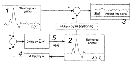
Figure 21 is a flow chart illustrating an application of the method of the
invention. The
raw digitized signal, containing both the desired signal and contaminating
artifact are
shown as (1) in Figure 21. It is strongly preferred, fox the invention to work
optimally,
that the signal in (1) be faithfully (linearly) recorded and that the
digitization be timed
with adequate precision to the artifact. To produce the corrected signal, an
estimate of
23
CA 02418478 2003-02-10
WO 02/13689 PCT/USO1/25480
the artifact (2) is simply subtracted from the raw signal. Optionally, the
estimate of the
artifact may be multiplied by an amplitude constant, m, to account fox
differences in the
magnitude of the coupling of the artifact to the signal recording system.
The artifact estimate can be computed as follows: Each time a new raw sample
(1) is
available, it is added to the current estimate of the artifact (2) which has
been multiplied
by a scalar amplitude constant, w (4). This summed signal is then divided by
the sum of
the series 1 + w + w2 + w3 + . . . resulting in a new representation of the
artifact (5),
which then replaces the value used for (2). ~Uhen w is a number less than 1,
the process
results in a leaky average, where more recent signals have a greater influence
on the
1o estimated artifact (2) than do less recent signals. In this way, the system
adapts to slow
changes in the artifact, if necessary. For the purposes of this disclosure, we
have called
this implementation a "leaky avexagex."
More formally, if R[n~ is the n~ raw signal collected, A~~t~ is the estimated
artifact for
collection ~t, and S ~n~ is the artifact-free signal:
~j2~ - R[n]+WA~n -l~
n
Wi
iL~~
f2
~Wl ~l2 -l
_ i=~
n
~Wa
i~
and
S[nl ~ ~n ~ _ A[h l .
In the leaky avexager discussed above, the influence of temporally distant
data decreases
with time. It would be possible to determine w adaptively by looking at the
history of the
2 o estimated artifact. If the axiifact is changing quickly, w should be made
smaller (reducing
the influence of older frames on the current correction). Conversely, w should
be large if
14
CA 02418478 2003-02-10
WO 02/13689 PCT/USO1/25480
the artifact is very stable. In the limit, if the artifact cannot change over
time, A(n] should
be the simple average of all of the samples (w=1). If the algorithm is to be
used in real-
time, A[n] will be the average of all samples until time n. If it is used "off
line" A(n] will
be the average of all samples both prior to and after time n.
It is possible to determine the value of m adaptively as well, approximating
it as the
amplitude that mirimi7es the correlation between S(n] and A[n-7].
The method is particularly suitable for electrical recordings which comprise
an
electrophysiological signal, such as an electroencephalographic recording, an
electromyelographic recording, an electrocardiographic recording or a measure
of
~ galvanic skin resistance. The method is applicable as well to other types of
electrical
recordings, including audio recordings. In some embodiments, the interference
comprises interference arising from inductively coupled magnetic fields. The
interference can also comprise interference arising firom other sources, such
as
alternating current (AC) line noise.
It is particularly advantageous that, in accordance with the invention, the
digitizing can
be performed at a sampling rate below the Nyquist rate for the contaminating
signal. In
one embodiment, the electrical signal obtained is passed through a low pass
filter prior to
the digitizing, at a frequency of approximately one half of the frequency at
which the
electrical signal is sampled. For example, the low pass filter may pass signal
frequencies
2 0 of less than about 200 Hz.
The method can be performed concurrently with Magnetic Resonance Imaging of
the
subject. In one embodiment, the electrical signal comprises an
electrophysiological signal
and the contaminating signal comprises gradient activity. Examples of a
contaminating
signal include radio frequency transmitter activity. In a preferred embodiment
of the
2 5 method, the digitizing is performed at a rate of about 200 to about 5000
samples per
second. The digitizing can be performed at rates below 200 and above 5000
samples per
second, with representative rates including 100, 250, 500, 1000, 2000, 3000,
4000 and
6000 samples per second.
CA 02418478 2003-02-10
WO 02/13689 PCT/USO1/25480
The invention additionally provides a method of removing a DC offset from the
electrical signal by analog subtraction prior to the digitizing. Preferably,
the DC offset is
measured and subtracted from the electrical signal using a difference
amplifier. In one
embodiment, the DC offset is measured by analog to digital conversion, and
averaged
over a time period long compared to the lowest frequencies of interest in the
electrical
signal. An example of such a long time period is approximately 10 times longer
than the
lowest frequencies of interest in the electrical signal. For example, where
lowest
frequencies of interest axe approximately 3 Hz, the time period is about 30
seconds. In
one embodiment, the analog subtraction comprises converting the averaged
signal to an
1 o analog voltage and electrically subtracting the averaged signal from the
electrical signal
through differential amplification. In another embodiment, the DC offset is
measured in
an analog integrator having a time constant long compared with lowest
frequencies of
interest in the signal.
The method of the invention is useful for electrophysiological recordangs,
such as an
electroencephalogram that is recorded concurrently with magnetic resonance
image
acquisition. In a preferred embodiment, the electrophysiological recordings
are used to
inform interpretations of magnetic resonance images. The electxophysiological
recordings can be used in a statistical analysis of change in intensity of the
magnetic
resonance signal. The method can further comprise determining a correlation
between
2 o change in intensity of the magnetic resonance signal and a feature of the
electrophysiological recording. The correlation can be used to make
statistical images, or
image maps, that represent an association between the electrical signals and
the intensity
of the magnetic resonance signal intensity. In one embodiment, the feature of
the
electrophysiological recording comprises a time course of signal intensity
change in
2 5 defined frequency bands contained in the electrophysiological recording.
The defined frequency bands can be selected to correspond to standard ranges
used for
clinical interpretations of the electroencephalogram. Representative standard
ranges are
selected from the group consisting of from 0 to approximately 4 Hz (the Delta
band),
from approximately 4 to approximately 8 Hz (the Theta band), from
approximately 8 to
1G
CA 02418478 2003-02-10
WO 02/13689 PCT/USO1/25480
approxitnately 12 Hz (the Alpha band), from approximately 12 to approximately
30 Hz
(the Beta band), and from approximately 30 Hz and greater (the Gamma band).
Typically, the frequency bands for this application will not extend beyond 300
Hz. In
one embodiment, the method further comprises convolving the time course of the
electrophysiological signal with an estimate of the magnetic resonance
hemodynamic
impulse response function. In this embodiment, the time course of the
electrophysiological signal is suitably conditioned to more accurately reflect
the
anticipated time course of the magnetic resonance signal change.
The invention additionally provides a method of reducing magnetic interference
during
1o electrophysiological recording from a subject by measuring an electrical
potential
difference between a pair of electrodes, wherein the pair of electrodes
communicate with
a differential amplifier via electrical connections, the method comprising
twisting the
electrical connections together, thereby reducing magnetic interference. Also
provided is
a method of reducing magnetic interference during electeophysiological
recording from a
15 subject by measuring an electrical potential difference between a pair of
adjacent
electrodes, wherein each electrode comprises two leads, the method comprising
twisting
each lead together with a lead of an adjacent electrode, thereby reducing
magnetic
interference. In one embodiment, the electrophysiological recording comprises
an
electxoencephalographic recording. The method can be performed concurrently
with
2 o Magnetic Resonance Imaging of the subject.
Apparatus
The invention further provides an apparatus for processing digitized
electrical signals in
the presence of a repeated contaminating signal. The apparatus comprises a
signal
processor 90 adapted to receive a recording of an electrical signal; a
detector 92 adapted
2 5 to detect a timing signal that occurs at a fixed time point during an
electrical signal
relative to the onset of a contaminating signal; a signal accumulator 94 to
contain the
estimated contaminating signal; and a processor 96 adapted to subtract
averaged
wavefonns from an electrical signal. Representative variations of the
apparatus are
described in Figures 3, 14,19, and 20.
17
CA 02418478 2003-02-10
WO 02/13689 PCT/USO1/25480
The signal processor 90 adapted to receive a recording of an electrical signal
may be, for
example, an electronic circuit (IC) consisting of a integrated differential
amplifier such as
a an INA114 from Burr Brown Corp., with a DC offset reference provided through
measurement by a sample and hold IC such as the LF298 from National
Semiconductor
corporation, a low pass active filter and an output buffer all made using
standard
operational amplifier ICs. In this embodiment, the detector can also include a
means of
analog to digital conversion, such as a National Instruments NI 6031E
installed in a
personal computer.
The detector 92 adapted to detect a timing signal that occurs at a fixed time
point during
1o an electrical signal relative to the onset of a contaminating signal may
be, for example,
an optoisolator IC whose output is conditioned using an IC such an LN555 from
National Semiconductor corporation to produces a TTL compatible trigger signal
which
is then presented to an analog to digital convertor such as a National
Instruments NI
6031E installed in a personal computer.
15 The signal accumulator 94 may be implemented, for example, in software in
the 'C'
programming language as a vector of numbers, or in the National Instruments
LabView
programming language as an array of numbers. Either of these may be executed
on a
personal computer. The signal accumulator 94 can be, for example, a signal
averager.
Other methods, in addition to signal averaging, can be used to generate an
estimate of
2 0 the contaminating signal.
The processor 96 adapted to subtract averaged waveforms from an electrical
signal may
be implemented, fox example, as a processing routine in the 'C' programming
language ox
the National Instruments LabView programming language n,nning on a personal
computer. Those skilled in the art will appreciate variations on the above
examples of
25 apparatus elements that will serve the same processing, detecting and
accumulating
functions in accordance with the methods of the invention.
18
CA 02418478 2003-02-10
WO 02/13689 PCT/USO1/25480
Overview of EEG and fMRI in Simultaneous Recording and Ma~~ing
Electroencephalography (EEG) is established firmly as a means to probe changes
in
electrical signals recorded from the scalp that accompany behavioral tasks,
and as a
marker for clinical, cognitive or neural states. Detexmination of the three-
dimensional
localization of the EEG signal is ambiguous because the relationship between
the actual
position of multiple electrical dipoles and the distribution of electrical
potentials detected
at the scalp has no unique solution. Functional Magnetic Resonance Imaging
(fMRl~ uses
modulations in the magnetic resonance signal that depend on variations in
blood
oxygenation to distinguish brain regions whose activity is increased or
decreased with
task demands. The following describes a set of solutions to the technical
problems in
simultaneous recording of fMRI and EEG and shows that data from the two
methods
may be combined to create tomographic images indicating brain regions whose
activity
changes as a fiuzction of EEG signal intensity in the classically defined
spectral bands.
Significance and Interpretation of the EEG
Study of the electroencephalogram (EEG) is more than a century old (Caton
1875). The
phenomenon is highly robust: namely that electrical potentials exist at the
surface of the
head that ate correlated strongly with ongoing cerebral activity and fluctuate
with sleep
stages (Rechtschaffen and Kales 1968; Buchsbaum, Mendelson et al. 1982; Benca,
Obermeyer et al. 1992), emotional state (Davidson, Schaffer et al. 1985;
Davidson 1988;
2 o Ekman, Davidson et al. 1990; Lambent and Robertson 1999), attention
(Klimesch,
Doppelrnayr et al. 1998; Wrobel 2000), therapeutic drug doses (Loo, Teale et
al. 1999;
Alvarez, Lombardi et al. 2000), traits, such as "aggressiveness" (Fishbein,
Herning et al.
1989) and with circulating levels of a wide variety of drugs of abuse
(Cezayirli, Little et dl.
1975; Maykut 1985; Tokunaga, Takeichi et al. 1989; Abraham and Duffy 1991;
Mannelli,
Jatllri et al. 1993; Bauer, Gross et al. 1997). Despite the considerable
history and attention
to this measurable phenomenon, the origin of the EEG signal and the
localization of its
sources (presumably cerebral), is still not known. The situation is somewhat
more
favorable with evoked potentials (EP's, in some contexts known as evoked
response
potentials or ERP's) for which the temporally discrete nature, and the motion
across the
19
CA 02418478 2003-02-10
WO 02/13689 PCT/USO1/25480
scalp, of the surface potentials combine to give a better indication of the
deep dipole or
dipoles that generate the signals, but it has been difficult to test directly
the relationships
between scalp EP and brain activity, especially for sources significantly
below the cortical
surface. For example, attempts to localize the generators of the brainstem
auditory
evoked response by simultaneous recording with depth electrodes or correlation
with
lesions have been conclusive for only a subset of the waveform components
present in
the signal (Start and Achor 1978; Chiappa, Gladstone et al.. 1979; Achor and
Start 1980b;
Achor and Start 1980a; Goldie, Chiappa et al. 1981; Cohen and Britt 1982;
Chiappa and
Young 1985).
~Uhen Caton first reported on the resting and task evoked electrical activity
of the brain
in animals (Caton 1875), he was able to determine that there was a
transcortical electrical
potential that changed during periods of functional activity (sensory
stimulation). Caton
noted that, "Feeble currents of va~ing direction. . ." were generally present
between different
points on the cortical surface. Some years later, Bergen noted that scalp
potentials could
be recorded in humans with properties similar to those of Caton's cortical
potentials
(Bergen 1929) and he soon realized that this electroencephalogram varied
according to
the mental state of the subject (Bergen 1930). By 1930 Bergen had described
what he
called the alpha rhythm, being relatively high amplitude oscillations in the
range between
8 and 12 Hz that were associated with drowsiness. It is now accepted that
alpha activity
2 o is associated with a relaxed, awake state, usually with eyes closed.
EEG is now a routine and essential test in clinical neurology. It provides
diagnostic
information that cannot be gathered through any other commonly obtainable
means.
Indeed, its indispensability derives from this lack of other routine clinical
tools to assess a
broad region of cerebral neurophysiology with high temporal resolution. EEG
depicts
2 5 moment-to-moment changes in cerebral cortical function, and thus is
valuable in any
clinical context where such information would guide medical decision making.
Such
situations are not lirni.ted to electrophysiologic abnormalities, as other
pathologic
processes often affect neuronal functton and, thus, impact the EEG. These
include
ischemia, metabolic alterations, mass effect, and infection among others
(Markand 1984).
CA 02418478 2003-02-10
WO 02/13689 PCT/USO1/25480
Because it represents abnormality in neuronal electrophysiology, epilepsy is a
common
clinical problem that warrants the use of EEG (Engel 1984). Despite a central
place in
clinical neurology that has endured over most of the past century, the basis
of EEG is
still understood poorly. The generators of the potentials that sum to create
the waves are
understood better (McNamara 1994). However, the interaction between cell
populations
to create electric fields at the scalp has proven difficult to study.
By performing fMRI during EEG, one may obtain complementary information and
greater understanding of EEG and the clinical conditions that EEGs may
indicate. It
appears that solid results that characterize the relationship between scalp
potentials and
local brain activity will offer great value in guiding the clinician to
isolating specific
abnormalities. In fact, there are already scattered reports that interictal
spike discharges,
associated strongly with clinical epilepsy, might be used in combination with
functional
MRI (~Xlarach, Ives et al 1996; Seeck, Lazeyras et al. 1998; Krakow,
~Xloermann et al. 1999;
Patel, Blum et gal. 1999; Symms, .Allen et ~l. 1999; Schomer, Bonmassar et al.
2000) (or
z5 PET (Henry, Sutherling et al. 1991)) to identify surgically resectable
lesions , and
tomographic localization via MEG has been suggested as a means to guide such
resections (Stefari, Schneider et ctl. 1990). The use of fMRI during epileptic
seizures has
also been tested with success by Jackson Qackson, Connelly et al. 1994).
2 o EEG and Imagineleep Disorders and Staging
Based on unit activity, stimulation studies, and lesion studies in non-human
mammals,
brain regions active in non-REM sleep include the anterior hypothalamus,
dorsal bulbar
reticular formation, and nucleus of the solitary tract Qones 2000). Regions
likely
associated with REM activity, and possibly the generation of wakefulness,
include the
25 posterior hypothalamus, ventral mesencephalic pons, basal forebrain, and
pontine
reticular formation. Such localized brain activity should also be visible in
humans
through functional neuroimaging. Both PET and SPECT have been used to examine
regional activity changes (via cerebral metabolism and blood flow
respectively) with sleep
stage (determined electroencephalogxaphically). These imaging studies have
broadly
3 o indicated that areas thought to be involved in the active generation of
rapid eye
21
CA 02418478 2003-02-10
WO 02/13689 PCT/USO1/25480
movement (REM) sleep axe active during this stage of sleep and in non-rapid
eye
movement (NREM) sleep.
Maquet and colleagues (Maquet, Dive et al. 1990) noted that rates of cerebral
glucose
metabolism (rCMRGlc) during NREM axe lower, overall, compared to those during
wakefulness (most notably in the thalamic nuclei), and that REM sleep xCMRGlc
is
comparable to the awake state. Furthermore, the greater the depth of the NREM
sleep
(i.e., the greater the amount of cortical synchrony), the lower the xCMRGlc
(Ingvar,
Baldy-Mouliniex et al. 1965; Madsen, Holin et al. 1991; Maquet, Dive et al.
1992).
to Especially intriguing is the observation that changes in cerebral blood
flow show
substantial regional heterogeneity. REM-associated increases in xCBF have been
observed in the pontine tegmentum, thalamus, limbic areas, cortical areas
(notably the
anterior cingulate cortex), and visual association areas, with a decrease in
the doxsolatexal
prefrontal cortex, parietal cortex, posterior cingulate cortex, and pxecuneus
(Madsen,
Z5 Holin et al. 1991; Madsen, Schmidt et al. 1991; Maquet, Peters et al. 1996;
Nofzingex,
Mintun et al. 1997; Braun, Balkin et al. 1998). Interestingly, xCBF increases
have been
observed in the extrastriate visual areas, though not the priinaxy visual
cortex which may,
as has been hypothesized by those authors, be indicative of some sort of
visual memory
activation during sleep (Braun, Balkin et al. 1998; Maquet and Phillips 1998;
Maquet
2 0 1999).
As an example of the relevance of imaging during sleep, current studies
suggest a role for
sleep in memory consolidation, based on changes in sleep blood flow as a
function of
daytime activities (Maquet, Laureys et al. 2000). There axe also itnpoxtant
corxelations
25 between sleep and a variety of psychiatric disorders (Benca, Obexmeyex et
al. 1992) that
might expose sleep physiology as a marker for these problems. But, due to the
coarse
temporal resolution of PET and SPECT (Nofzingex, Mintun et al. 1998) and the
relatively rapid changes in brain activity during sleep, neither of these
imaging methods is
suited ideally for this purpose. Very recently, there have been reports of the
use of fMRI
3 o in assessment of localized signal changes that take place during sleep
(Lovblad, Thomas
22
CA 02418478 2003-02-10
WO 02/13689 PCT/USO1/25480
et al. 1999; Home 2000) that indicate an increase in occipital lobe activity
and a decrease
in the frontal lobes during REM, in agreement with the PET findings. However,
such
studies cannot be considered definitive without the incorporation of sleep
staging by
electroencephalographic means (Lovblad, Thomas et al. 1999). EEG-fMRI provides
an
excellent solution.
The sleep electroencephalogram can be defined by characteristic frequency
patterns, and
brief electrophysiological phenomena such as k-complexes and sleep spindles.
Furthermore, during REM sleep, there is a descending suppression of muscle
tone,
1o saccadic eye movements, and the loss of the cortical synchrony that is a
hallmark of
NREM sleep. Only with temporal resolving power of fMRI will it be possible to
study
activations associated with these transient events. One application of the
invention is to
assess changes in regional brain activity using fMRI and to correlate such
activity to
classically defined sleep architecture and features. For example, the
invention can be used
15 to seek an understanding the brain activity that underlies the general lack
of
responsiveness to external stimuli, the apparent gating of motor output and
dream states.
Functional MRI (fIVIRI) is now an established method for the localization of
focal areas
of brain activity, chiefly in humans (Cohen and Bookheimer 1994). Although it
is
assumed that the fMRI signal arises from local changes in blood oxygen content
(Ogawa,
2 o Lee et al. 1990a; Ogawa, Lee et al. 1990b; Kwong, Belliveau et al. 1992;
Ogawa, Tank et al.
1992), this theory has not been subjected to extensive direct testing, and the
mechanism
of coupling between neuroelectrical activity and MRI signal changes is still
the subject of
speculation. Nevertheless, the observed areas of signal increase correlate
well with both
extensive literature on neurophysiology and, more recently, with electxo-
coxticography
25 derived of humans in surgical settings (Schulder, Maldjian et eel. 1998;
Roux, Boulanouax
et al. 1999; Lurito, Lowe et ~L. 2000). ~Uhil.e there is a growing literature
that attempts to
use the localization power of fMRI to aid in the interpretation of the study
of evoked
responses, there is a striking paucity of reports that attempt to reconcile
the findings in
EEG with functional MRI.
23
CA 02418478 2003-02-10
WO 02/13689 PCT/USO1/25480
The classical or posterior alpha rhythm is found mostly in occipital,
parietal, and
posterior temporal regions (Adrian and Matthews 1934), and first emerges at
about 4
months of age as a 4 Hz oscillation, present with eyes closed and blocked with
eyes open.
The frequency of this rhythm increases with age, reaching about 8 Hz by age 3,
and by
about age 10, it reaches the average adult frequency of 10 Hz (Petersen and
Eeg-
Olofsson 1971). Although recognized since the beginnings of EEG, little is
known about
the functional significance of this alpha rhythm; it reflects essentially a
state of relaxed
wakefulness, and can be used as an indirect measure of brain activation, for
increased
alpha band activity is thought to correspond to decreased activity in
underlying cortex
(Shagass 1972). Thus, decreased alpha activity, or stimulus-induced alpha
blocking, has
been termed "event related EEG desynchronization" (Pfurtscheller and Aranibar
1977).
Davidson and colleagues have shown that alpha asymmetry recorded in anterior
regions
correlates with emotional reactivity, and that these asymmetries appear trait-
like in
waking and in sleep (Petersen and Eeg-Olofsson 1971). Studies in animals have
suggested the thalamus as a possible generator of the alpha rhythm (Petersen
and Eeg-
Olofsson 1971). Lopes da Silva demonstrated significant thalamocortical
coherences in
dogs between lateral geniculate nucleus and pulvinar and the cortex (Lopes da
Silva,
Lierop et al.. 1973; Lopes da Silva, Vos et al. 1980). Recently, in humans,
Lindgren and
colleagues showed an inverse correlation between EEG alpha power and thalamic
2 o metabolic rate in normal subjects using PET (Lindgren, Larson et al.
1999).
Challenges in Combining fMRI and EEG
Even in the best of circumstances, EEG signals recorded in the clinical
environment are
relatively noisy. The effective input resistances are large, and the signals
axe small. As a
result, Boltzmann noise limits the ultimate signal to noise ratio. LYlith a
typical 5 MS2
input impedance, the Boltzmann noise will be approximately 1.5 ~,V (v~ = 4kTBR
,
where k is Boltzmann's constant, Tis the temperature, B is the bandwidth and R
is the
equivalent resistance) even over the limited bandwidth of 100 Hz or so used in
the EEG.
Since the scalp potentials are typically only a few ~.V, the signal to noise
ratio (SNR) of
the EEG seldom exceeds 100:1. Because EEG is often analyzed in the spectral
domain
24
CA 02418478 2003-02-10
WO 02/13689 PCT/USO1/25480
over narrow bandwidths, the effective SNR for detection of band-limited signal
(for
example, alpha intensity) may be somewhat higher.
Beyond the thermal noise limit, other factors further reduce the SNR of EEG.
Caxdio-
electric (EKG) and myoelectric (EMG) signals add contamination. Corruption by
the
EKG is variable across individuals; though always present, it is usually
smaller than the
EEG, but at times can become comparable in amplitude. The EMG is typically a
contaminant for only brief periods of head or facial muscle contraction, such
as eye
blink, grimace, etc. The methods of the invention actually serve to reduce the
EKG
artifact that would be present whether or not the subject is scanned in the
magnet. All
1o told, these sources of noise reduce the useable dynamic range of the total
EEG signal
dramatically for virtually all purposes.
Noise in the MRI Environment
The noise environment for EEG becomes radically worse when subjects are placed
inside an MR imaging system. Almost all of the noise sources, however, are
coupled
l5 magnetically to the EEG. Several of these axe non-biological, including:
amplifier noise
in the shim and field gradient amplifiers; large time-varying magnetic fields
induced by
the field gradients during scanning, and radio-frequency signals generated by
the scanner
fox magnetic resonance induction. By Faraday's law, the magnitude of the
voltage
induced by these time varying fields is proportional to the first time
derivative of the flux,
2 o and thus to the amplitude of the magnetic field, itr first tune
derivative, and the area
enclosed by any conducting loop. More specifically:
e.»a.f =d~ldt,
where e.mf, is the induced electromotive force, and ~ is the magnetic flux. In
MR
imagers these sources cannot be reduced in any practical way. The MR imaging
gradients
2 5 in state-of the-art imaging instruments slew at an extremely high rate;
the field gradients
on a typical scanner operate at 80 T/sec and are thus major sources of noise;
the newest
generation of MR instruments, with local head gradients, will slew two to
three times
CA 02418478 2003-02-10
WO 02/13689 PCT/USO1/25480
faster. The RF pulses, though only about 50 milliGauss, have fundamental
frequencies, at
the 3 Tesla operating field, of 128 MHz. Slewing at 4000 T/s, they too are
large sources
of noise.
Physiological noise sources axe present also. Even small motions of the
subject are
coupled to the EEG as the leads move within the large static magnetic field.
Not only
s'rmin_or fidgeting, but also the motion of the whole body with each heartbeat
(the
ballistocaxdiogxam), produces signal in the ~,V to mV range.
DC Offsets and Transient Recovery
The scalp electrical potentials used in the EEG contain both time varying and
static (DC)
1o components. Often the DC signal is much larger than the EEG, but it is
seldom of
interest for clinical diagnostic purposes (note reference to true DC offsets,
not to slowly
varying potentials), as it contains essentially no information. However, it
does cause
trouble fox the EEG in several ways. Typically, the DC offset increases the
dynamic
range needed to digitize the EEG signal. For example, the EEG signal may be
only a few
15 ~,V, while potentials of a few mV may exist between electrodes, or as a
result of the
chemical electrode potential. The signal digitization depth will be reduced by
the ratio of
the EEG to the DC potential. For example, assuming a DC offset of 10 mV and an
EEG signal of 10 ~,V, the 4096 different levels xepxesentable by a 12 bit
analog to digital
converter (ADC) will be reduced to only 4 levels for the EEG. Clearly this
loss is
2 o unacceptable, as quantization noise will dominate the signal.
For these reasons, conventional EEG amplifiers axe equipped with AC-coupled
(high
pass) inputs, usually a capacitor separating the first stage ainplifiexs from
the input to the
ADC. The inputs will usually have time constants of several seconds, allowing
frequencies of 1 Hz or so to pass unattenuated. One consequence of this AC
coupling is
25 that it creates a time constant for signal recovery if the input saturates.
Because these
filters must pass very low frequencies, the recovery time for the analog
signal to come
back to the center of its nominal range can be quite long.
2G
CA 02418478 2003-02-10
WO 02/13689 PCT/USO1/25480
In fMRI, the recovery time associated with AC coupling is a substantial
problem, as the
gradient-induced artifacts (tens of mV) can be large enough to saturate the
input stages,
pinning them to the positive or negative supply rails for several cosec.
~Xlhen the
gradients cease, the settling tune of the high pass filter greatly outlasts
the gradient event.
A recent paper studying EEG-fMRI combinations, reported that, "The EEG could
not
be interpreted during the artifact caused by the excitation pulse, but the
recording
becomes readable in less than 1 second (approximately 100 cosec) after
completion of the
BURST" (Hennig and Hodapp 1993; Lovblad, Thomas et al. 1999). This problem can
be
mitigated by using the methods of the invention, including an artifact-
reducing electrode
1 o configuration and an input amplifier (Grass-Telefactor) with enough
headroom to stay
out of saturation prior to the high pass stage. As disclosed herein, the
invention further
provides a more complete solution that avoids the high pass filter completely.
Gradient Noise
The magnetically-induced gradient noise is of very large amplitude (milliVolts
in a typical
scanner) as compared to the EEG, especially in the context of echo-planar
imaging. One
group has implemented a correction scheme for gradient artifacts that is
similar to a
scheme that group developed for ballistocardiogram removal (Allen, Josephs et
al. 2000).
Because the fundamental frequencies of the gradient activity are much Higher,
they
developed special recording hardware that allowed them to use a much higher
digital
2 o sampling rate of 5 kHz, which they selected as being rapid compared to the
nominal
Nyquist frequency for the gradient waveshapes. Unfortunately this is not
sufficient, as
sampling at the Nyquist rate guarantees only against abasing of the higher
frequencies
into the pass band, but does not effectively remove the artifact.
For example, assume that there is an undesired signal consisting of a sinusoid
at 1000 Hz
contaminating the EEG, which is sampled digitally at 5 kHz. Because the
gradient and
digitization activity are clocked independently, and are asynchronous, the
phase at which
the artifact is sampled can vary by as much as 2~c/5 (72° or 200 ~,s at
this frequency).
Over extended sampling periods (typically five minutes or more in an imaging
experiment), it is likely that the relative timing of the scanner and sampling
clocks will
27
CA 02418478 2003-02-10
WO 02/13689 PCT/USO1/25480
differ to this degree. Figure 9 shows this effect. In this simulation, the
artifact is assumed
to have been sampled at the points indicated by closed circles. At a later
time, the
sampling has drifted with respect to dze gradients by 200 ~,s (dashed line,
open circles).
The difference signal is the residual axtifact, in this case just over 17%
greater than the
uncorrected signal. To mitigate this problem, the Allen group has adopted a
sophisticated
interpolation scheme that is successful in minimizing the residual
contamination. The
present invention provides a much more effective approach based on an
alternative
formulation of the digital sampling problem.
The methods disclosed herein have made it possible to effectively eliminate
1o contamination of the EEG signal by the most severe sources of noise present
during
' MRI scanning in general, and in functional MRI in particular. In one
embodiment
described herein, the method has been used in the construction of tomographic
maps of
brain activity corresponding to the energies in spectrally-defined components
of the
EEG.
l5 ' Theory
Digitization
The artifact from gradient activity is large and contains substantial energy
at high
frequencies. Figure 10 shows the timing of a typical echo-planar imaging
sequence, as
used in typical functional studies. The lines for Select, Phase and Readout
indicate the
2 o amplitudes of the three orthogonal magnetic field gradients used for
imaging. The fourth
line indicates the timing of the radio frequency channel (only the amplitude
envelope is
shown for the RF, as the carrier frequency of 128 MHz is not visible at this
resolution.)
Immediately apparent is the very large high frequency (1400 Hz) oscillation of
the
readout gradient (shown at half the vertical magnification of the other
gradients).
2 5 Figure 11 shows raw signal, recorded from an EEG system at a sampling rate
of 10 kHz,
following analog low-pass filtering at 100 Hz. The insets on the bottom of
this figure
show expanded representations (10~ of the indicated regions of the signals.
When EEG
28
CA 02418478 2003-02-10
WO 02/13689 PCT/USO1/25480
data aa:e acquired during scans, the MRI field gradients induce voltages much
higher than
the cortical signal. Comparing this and the previous figure reveals that the
magnitude of
the high frequency components is reduced dramatically by the low pass filter,
and that
the residual artifacts outlast the gradients themselves.
Though the low pass filter provides at least 100-fold reduction in the 1400 Hz
oscillations, it does not remove the transients as these gradients turn on and
off. These
contain energy at very low frequencies, as well. The AC coupled input stage,
in this
traditional amplifier, is responsible for the extended ring-down of the
artifacts (the
saturation recovery alluded to previously), although it is much better than
the 0.1 to 1 s
1 o ring down reported by others (Lovblad, Thomas et al. 1999), presumably due
in laxge part
to the attenuation provided by the differential recording apparatus, which
helps to
prevent the amplifiers from going into saturation.
~Xlhen applying cyclic averaging techniques to this data set (Allen, Josephs
et al. 2000) as
shown in Figure 11, they are reasonably effective in attenuating the effects
of the low
frequency components, they are largely i~aeffective at removing the high
frequency
content. This, as described above, results from the asynchronous sampling. The
residual
(worst case) error from sampling too slowly can be predicted from the maximum
phase
shift, cp
s = cos(2~ft + gyp) - cos(2~ft)
= cos(2~ft)(cos ~p -1) - sin(2~ft) sin cp
2 o The maximum phase shift, cp, that can occur at a given sampling rate is
equal to 2~fo/fs,
where f5 is the sampling frequency, and f0 is the frequency of the EPI
readout.
Comparing the residual artifact during the two scan periods (two expanded
frames at
bottom of Figure 11) reveals that the cancellation efficiency is unstable as a
consequence
of the asynchronous timing of the gradient activity and sampling device, which
causes
the sampling offset, cp, to drift over time.
29
CA 02418478 2003-02-10
WO 02/13689 PCT/USO1/25480
As the sampling rate is increased, the cancellation will become more accurate.
Using the
approximation that for small «, sin« ~ « and cos« ~ 1, one can see that in
this regime s is
approximately proportional to cp. It follows that if the artifact must be
suppressed by 100
fold, the signal must be digitized at approximately 100*2*~ times the highest
frequency .
of interest, in this case (the 1400 Hz readout) about 880 kHz/channel, which
is
impractical for reasons of both cost and overall data handling. In any case
the acceptable
sampling error is predicted readily by this formula given the low pass filter
characteristics
and the desired final signal to noise.
The data above were sampled at 10 kHz, well above the 2800 Hz Nyquist
criterion for
1o the high frequency components of the signal. Figure 12 shows the efficiency
of artifact
subtraction based simply on rapid sampling. On the top is shown the raw
artifact. Below
it is shown the residual artifact that remains after subtraction if the timing
of fhe
sampling and the scanner have drifted from synchrony by 100, 200 and 400 ,sec,
corresponding to the worst case errors for sampling at 10 kHz, 5 kHz and the
15 approximate Nyquist rate of 2500 Hz, respectively. It is immediately
apparent that the
residual artifact, after subtraction, is large even with the smallest timing
offset. In the
graph at the bottom of Figure 12, which shows in greater detail only the echo-
planar
readout segment of that data, one can see that the simple subtraction actually
increases
the magnitude of the artifact, as predicted in the equation above (and in
Figure 9).
2 o The efficiency of the subtraction of the gradient artifacts is effectively
independent of
sampling rate, and a repeated single sample, properly timed, can be used to
correct fox the
artifact at diet time point completely. This general finding is shown in
Figure 13 which
shows the same effects of timing shifts at a low sampftng rate of 200 Hz, well
below the
Nyquist rate (the gradient activity is aliased into the digitized EEG signal).
As in the prior
2 5 example, the magnitude of the residual artifacts increases as the sampling
is delayed with
respect to the scan timing. Its magnitude is no worse than that seen with more
rapid
sampling.
It is clear that if the sampling is timed precisely to the gradient activity,
the residual errors
will be eliminated much more effectively. Perhaps less intuitive is the fact
that this does
CA 02418478 2003-02-10
WO 02/13689 PCT/USO1/25480
not require Nyquist rate sampling for the artifact frequencies. Time (phase)
shift and
frequency can be seen as "duals": Perfect sampling needed for artifact
subtraction could
be achieved by sampling at infinitely high frequency with arbitrary tinning or
with precise
synchronization at an arbitrarily low sampling rate. To yield the same 100:1
suppression
that requires 880 kHz sampling, the sample timing would require an accuracy of
1/880
kHz, or 1.14 sec. Ideally, the residual scanner axtifact should be small
compared to the
thermal noise of the EEG signal. With analog filtering and proper recording
technique
(outlined in the examples below), the scanner artifact is about ten times the
amplitude of
the EEG. Assuming an EEG signal to noise ratio of 100:1, a thousand-fold
suppression
Zo is needed in the digital processing, achievable with either 8.8 MHz/channel
sampling
(which could come only at tremendous expense in the digitization hardware), or
with an
easily achieved 114 nsec timing accuracy
' EXAMPLES
The following examples are presented to illustrate the present invention and
to assist one
of ordinary skill in making and using the same. The examples are not intended
in any
way to otherwise limit the scope of the invention.
Example 1: Acquiring simultaneous EEG and functional MRI
Methods
EEG Device and Lead Placement
2 o The EEG device incorporates numerous hardware modifications to reduce
artifact in
concurrent EEG/fMRI, and was provided by Telefactor Corporation (~U.
Conshohocken, PA). Signal is detected from the-scalp using silver chloride
plated plastic
cup electrodes connected to a compact magnet-compatible local amplifier
(headbox) via
10 foot carbon fiber leads with a resistance of 1 kSZ/foot. This design
minimised both
2 5 artifact in the MR images and the induction of RF current loops in the
lead wires.
A lead configuration was devised that minimised unwanted current induction by
recording EEG in a hard-wired montage using special dual lead electrodes. The
lead
31
CA 02418478 2003-02-10
WO 02/13689 PCT/USO1/25480
wires from each electrode pair were twisted together over their entire length,
forming a
chained bipolar montage for each hemisphere ~2 f8, ff-t4, t4-t6, t6-o2, 02 p4,
j~4-c4, c4 f4,
f4 fp2; fjo fl, fl-t3, t3-t5, t5-o ~, o ~ p3, p3-c3, c3 f3, f3 fp ~). The dual
leads allowed each
differential pair to be twisted together (Figure 1A-B and Figure 2A). The
resulting
configuration leaves only small loops at the head in which current can be
induced. As
shown in Figure 2B, currents induced by motion and gradient switching should
be self
canceling, for the current induced in consecutive twists will flow in opposing
directions
in each lead wire.
The magnet-compatible headbox contains 32 separate channel inputs, each with a
1 o differential amplifier coupled to an RC filter having a time constant of
0.25 cosec.
Sixteen channels were used to record EEG, and two additional channels were
used for
electrocardiogram (EKG). EKG was acquired using a pair of twisted single lead
electrodes placed above and below the heart on the subject's back. This
placement
minimized lead motion, and thus electrical artifact, due to breathing. A scan
trigger
15 channel was also used to receive a pulse from the scanner every TR to aid
in post-
processing of the data. The signal was filtered in all channels with a band
pass of 0.5-70
Hz to further attenuate high frequency noise. A single lead was connected at
c~ to
headbox ground as an added patient safety measure, but was not used as a
montage
reference.
2 o The signal was fed to a battery powered isocoder containing an A/D
converter where it
was sampled at 200 Hz., and the digitized signal was carried out of the
shielded magnet
room via optical fiber to maintain the scanner's electromagnetic isolation.
After
translation to TTL, the data were routed to a Telefactor Digital EEG (D/EEG)
(4S6
computer). The EEG data could then be viewed in real time and sent off Line
via a
25 l0baseT Ethernet connection to a post-processing and viewing station for
further artifact
attenuation.
32
CA 02418478 2003-02-10
WO 02/13689 PCT/USO1/25480
Scan Protocol
All subjects signed a consent form approved by the UCLA Human Subject
Protection
Committee prior to MR scanning, which was performed in a General Electric
(~Xlaukesha, ~X71~ 3T scanner modified for Echo Planar Imaging (EPl) by
Advanced NMR
Systems. No visual or auditory stimulation was provided to the subjects during
functional scanning.
Scout scans of the entire brain were first acquired to localize slice planes
parallel to the
AC-PC line through the occipital cortex. To acquire EEG during functional
scanning,
the scan protocol was then specified to allow windows of readable EEG between
1o gradient bursts. An EPI sequence was used with TR = 4000 ms, echo time (TE)
= 45
ms, 64 x 64 matrix, 20 cm x 20 cm field of view (FO~, 4 mm slice thickness,
and 1 mm
gap to collect 6 slices spaced evenly over the TR period, leaving a 580 ms
window of
readable EEG between each 90 ms period of gradient induced noise (an 87% duty
cycle).
An EPI sequence (TR = 6000, TE = 54, 128 x 128 matrix, 20 cm x 20 cm FO~ was
then acquired coplanar with the functional scans for use as an anatomical
reference.
Artifact Reduction Post Processing
Post-processing and viewing was performed on a Dell Inspiron 3000 Pentium PC.
After
importing data from the D/EEG over the wire, the EEG data was viewed with
Telefactor Twin software, and processed further using home-built software
described
2 o below to remove remaining artifacts. The residual artifact included both
noise from
e.m.f. induced by the magnetic field gradients (which appeared in the EEG when
a slice
is acquired) and ballistocardiogram. The latter occurred in a fairly regular
pattern just
lagging the Q wave of the EKG, but its morphology and amplitude differed in
each
EEG channel.
To suppress gradient noise and ballistocardiogram in the EEG record, the
gradient noise
was first removed by blanking the EEG and EKG data for the duration of each MR
slice
acquisition. Following a trigger every TR, the 90 ms data segments containing
scan
33
CA 02418478 2003-02-10
WO 02/13689 PCT/USO1/25480
artifact were replaced with zeros. Therefore, large deflections caused by the
MR
gradients did not corrupt the EEG data during the averaging and subtraction in
further
artifact removal.
Next, using a method similar to that of Allen et al. (Allen, Polizzi, Krakow,
Fish, &
Lemieux, 1998), sections of EEG were averaged together following a cardiac
trigger to
yield the ballistocardiographic artifact. To identify the initiation of each
cardiac pulse, a
single artifact-free QRS wave segment of the subject's EKG, recorded inside
the scanner
when no scanning was taking place, was used as a reference (see Figure 4A).
This
reference wave segment was compared to portions of the EKG data of the same
number
of data points as the reference segment that were shifted by one point at a
time, and
calculated a correlation coefficient (CC) for each data portion. ~XThen the CC
exceeded
an empirically selected value (typically 0.7), the peak CC following this
threshold crossing
was identified to trigger the initiation of ballistocardiogram averaging and
subtraction.
Figure 4B illustrates the averaging and subtraction algorithm performed on the
data in
each EEG channel. Every trigger-to-trigger section of raw EEG data (An) was
averaged
with all preceding sections. Because EEG and EKG should be uncorrelated, this
method averaged out the EEG signal and left only ballistocardiogram (B"). Data
sections were weighted inversely with their temporal displacement from the
current
sample to compensate for slow changes in the ballistocardiographic artifact,
calculating
2 o the ballistocardiogram in each trigger to trigger section using the
weighted average
n
~ W=~"
_;
B = t=0
n n
~W'
i=0
with a weighting factor w = 0.9. Thus, the earlier cycles formed an
exponentially
decreasing contribution with a time constant of roughly 10 sections. The
averaged wave,
Bn, calculated separately for each channel, was subtracted from that channel's
raw EEG,
2 5 An, to yield artifact free corrected EEG.
34
CA 02418478 2003-02-10
WO 02/13689 PCT/USO1/25480
Variations in section length due to changes in heart rate were accounted for
by averaging
sections point-by-point. The first data point in each section was averaged
with the first
data point in previous sections, the second with the second, etc. Data points
at the end
of longer sections were averaged with corresponding points in other long
sections, and
the weighting factors of each point were adjusted accordingly. To avoid
subtracting data
with too few points averaged, the subtraction was performed only if three or
more
points were used in the calculation; otherwise, the raw data remained in fine
final record.
Characterization of Noise Reduction
Noise Reduction due to Lead Dress: Phantom Studv
1o To characterize noise reduction due to the twisted dual-lead dress,
scanning experiments
were performed using a biological phantom - a 9 pound head-sized grocery store
roasting chicken - and compared twisted vs. untwisted lead arrangements. The
leads
were placed at distances corresponding approximately to standard international
10-20
positions on the phantom. The eight electrode chained twisted montage detailed
above
15 was placed on the left hemisphere, and on the right was placed a matching
dual lead non-
twisted montage. A scout scan was acquired to position the functional slices
to cover the
phantom. Functional EPI scans were then performed as described previously.
The EEG data were analyzed to quantify noise reduction due to the lead dress,
calculating the loss, in dB, using 30 second data segments as
Vt~~st
dB=20 to
2
~no-twist
where averages were taken over all twisted and all untwisted channels.
Gradient noise
reduction was calculated by subtracting the square root of the sum of the
squared
voltages without scanning from that during scanning, and then calculated
attenuation as
above.
CA 02418478 2003-02-10
WO 02/13689 PCT/USO1/25480
Noise Reduction due to Lead Dress: Human Study
To characterize twisted lead noise reduction further, the above study was
repeated on a
25-year-old normal male volunteer. Again, the chained twisted Iead set was
placed on
the subject's left hemisphere, and the untwisted set on the subject's right.
The subject's
EEG was recorded inside the MR scanner, both with and without scanning.
Spectral Anal;~sis
By restricting the timing of the EPI acquisitions to fall outside of the
frequency band of
interest for EEG (e.g., to study alpha activity, the scanning rate must be
less than four
images/second), it was possible to retain useful EEG spectral information. To
illustrate
1o this, the 25-year-old normal volunteer was scanned during three different
tasks known to
moderate alpha power - a basic eyes open/eyes closed task, a math task, and a
visualization task. All studies were performed during functional MRI as
described above.
A baseline eyes open scan was acquired, and then the three tasks were run as
follows.
In the eyes closed task, the subject was given verbal cues during the scan to
keep his eyes
15 open for the first two minutes, closed the next two minutes, then open for
the last
min-ute. For the next two tasks, the subject was told to keep his eyes closed.
First, the
subject was instructed to count backwards by sevens from the four digit number
given to
him two minutes into the scan. To verify that the task was performed, the
subject was
asked for the number he ended on after the three minutes of counting. Second,
the
2 o subject was instructed to visualize eating his favorite meal, again two
minutes into the
scan.
After post-processing the EEG to remove artifact, the alpha power in each TR
was
calculated using software developed in house. ~Xlith this software, the EEG
power in
user-defined bands with each TR was found using fhe Fast Fourier Transform.
Spectral
25 power in the alpha band was used as a reference function to calculate fMRI
signal maps.
3G
CA 02418478 2003-02-10
WO 02/13689 PCT/USO1/25480
Recultr
Noise Reduction due to Lead Dress: Phantom Study
EEG recorded on the phantom using the untwisted leads was substantially
noisier than
that recorded using their twisted counterparts. Figure 5 shows the recorded
EEG in both
twisted and untwisted lead channels. ~lUhen not scanning, the twisted leads
reduced
random noise power by an average of 5.4 dB. During scanning, gradients caused
large
artifacts in both the twisted and untwisted lead sets, but this noise power
was reduced by
an average of 6.3 dB in the twisted leads.
Twisted vs. Untwisted Leads on a Volunteer
1 o Figure 6 shows EEG data recorded on a normal volunteer inside the scanner
when no
scanning was taking place. Twisting the leads (shown here on the left
hemisphere vs. the
untwisted on the right hemisphere) reduced noise by an average of 7.5 dB
across all
channels.
Noise Reduction Due to Artifact Post-Processing
15 Figure 7 shows EEG recorded on a volunteer during functional MRI before and
after
post-processing. The post-processing removed significant gradient and RF
artifact, as
well as ballistocardiogram.
Spectral Data
The data shown in Figure 8 was recorded on a normal volunteer during an eyes
open,
2 o eyes closed paradigm using simultaneous EEG/fMRI. Here, four slices were
acquired
with a 2.5 second TR. When the subject's eyes axe closed, power in the alpha
band,
between 8 and 12 Hz, increases significantly. And as is expected, this alpha
signal is not
present when the subject's eyes are open.
37
CA 02418478 2003-02-10
WO 02/13689 PCT/USO1/25480
Discussion
Using a combination of analog pre-preprocessing and digital post-processing,
this
method allows one to record clean EEG during functional MR scanning. While the
EEG is obscured during gradient bursts, it recovers quickly after each slice
acquisition.
With this method, then, a trade off must be made between brain coverage in
functional
scanning and the fraction of useable EEG in the data record. Consideration
must also
be given to the timing of slice acquisition so that it does not overlap with
desired spectral
frequencies.
The invention provides a potentially powerful tool for localizing the sources
of various
1o EEG waveforms. Because the EEG is acquired simultaneously with fMRI instead
of
serially, it can be used as a direct source for the fMRI reference function.
In this way,
activation maps could be made of any relevant changes in the EEG: spike and
slow wave
patterns in epilepsy, spectral changes, or even event related potentials.
Example 2: Method for removal of artifacts in simultaneous EEG and fMRI
15 The strategy outlined below is applicable to any method involving digital
subtractive
noise cancellation, including EEG, EEG/fIVIRI, as well as any environment in
which
subtracted averages of artifacts are used to reduce noise.
Methods
EEG recording and electrode placement
2 o The basic approach of differential recording has been described previously
(Goldman,
Cohen et al. 2000; Goldman, Stern et dl. 2000). Paired silver electrodes are
placed on the
scalp surface attached with conductive electrode gel and check to ensure that
the
nominal impedance is less than 5 kS~ for each electrode. The electrodes are
themselves
attached to two carbon fiber conductors having a distributed resistance of
approximately
25 3 kS2/m. The wires are dressed in pairs with the leads from adjacent
electrodes twisted
together tightly to minimize electromagnetic pickup. This configuration offers
about 6
38
CA 02418478 2003-02-10
WO 02/13689 PCT/USO1/25480
dB attenuation of artifacts from gradient and baliistocardiographic noise
sources
(Goldman, Stern et al. 2000).
Amplification
Further improvements in the overall performance of in-magnet EEG can be
achieved
through the use of better analog electronics. Although the ballistocardiogram
contains
substantial energy in the range of most interest to clinical EEG (from 1 to 50
Hz), the
other main sources - gradient noise and RF transmit noise - have much higher
fundamental frequencies. In a typical scanner, for example, the overwhelming
majority of
the gradient-related noise is at a fixed frequency of 1400 Hz, with
significant energy
to distributions down to 100 Hz or less. The radio frequency energy, of
course, is at
radically higher frequencies well outside of the interesting pass band for
EEG.
Disclosed herein is a very simple circuit that corrects for much of the analog
portions of
the artifact (Figure 14). An initial gaits stage features a single pole filter
to attenuate the
large RF signals prior to sampling and provides enough gain to bring the EEG
signal into
the mV range without the artifacts causing saturation. The next stage offers
30
dB/octave attenuation at a corner frequency of 200 Hz (so that gamma range EEG
is
readily passed.)
The AC coupling problem is handled in the final amplification stage, which is
arranged
to include a resettable offset-nulling circuit that stores any DC offset
across a low-leakage
2 o capacitor. The offset nulling switch can be, e.g., a mechanical switch,
or, so that the
nulling can be performed under digital control as needed, presumably when the
software
detects that the signal is close to digital saturation, a CMOS switch. One can
reduce this
design to use with a pc and assemble a single channel of this system. Under
lab test
conditions, the circuit is able to hold the DC offset to within 1% for 10
minutes at a
time, easily meeting the system requirements fox MR scanning.
The AC coupling problem is handled in the final amplification stage, which is
arranged
to include a resettable offset-nulling circuit that stores any DC offset
across a low-leakage
39
CA 02418478 2003-02-10
WO 02/13689 PCT/USO1/25480
capacitor. The offset hulling switch can be, e.g., a mechanical switch, ox, so
that the
hulling can be performed under digital control as needed, presumably when the
software
detects that the signal is close to digital saturation, a CMOS switch. This
design has beep
reduced to printed circuitry and a single channel of this system has been
assembled. One
can reduce this design to use with a personal computer and assemble a single
channel of
this system. Under lab test conditions, the circuit is able to hold the DC
offset to within
1% fox 10 minutes at a time, easily meeting the system requirements fox MR
scanning.
Imag~ng~
Presented herein axe examples of activation mapping data from two subjects
(one each
to for the raw EEG data and for the EEG energy maps). Both subjects were
without
neurological or radiological abnormalities as assessed by a brief neurological
inventory
based on a form developed by the National Institutes of Health NIH and a
neurological
inventory performed by a board-certified neurologist. Beyond lying in the
magnet doting
scanning with eyes closed, the subjects performed no explicit cognitive task.
15 All scanning was performed on a General Electric (~Uaukesha, ~X1I) 3.0
Tesla Signa~
scanner modified by Advanced NMR Systems (~Uilrnington, MA) fox high
performance
echo-planar imaging (Brady, Cohen et al: 1991; Cohen, Kelley et al. 1996). For
testing of
artifact rejection, a 19 slice echo-planar data set was collected with a TR of
3 seconds,
TE =45 ms, 4 mm slice thickness and 3.125 mm in-plane resolution (64 x 64 scab
matrix
2 o and 20 cm FOV), to achieve appropriate weighting for "BOLD" contrast
effects
(Ogawa, Lee et al. 1990a). For the mapping data, after image-based shimming
(geese,
Davis et al. 1995) and collection of a scout scan, imaging was performed using
a gradient
echo EPI scan. as described above. These data, however, were acquired with a
longer TR
of 4 seconds and only four slice planes. The pulse sequence was modified to
include a 5
2 5 ~,s trigger pulse at the beginning of each TR period, the leading edge of
which was used
for synchronization of the EEG sampling acquisitions.
CA 02418478 2003-02-10
WO 02/13689 PCT/USO1/25480
Diglitization of the EEG
EEG data are acquired using a PCI-1200 (National Instruments, Houston, T~ on a
pc-
compatible microcomputer. Using LabView (National Instruments, Houston, TX~,
sampling software was developed that responds to the leading edge of the
scanner trigger
by acquiring a fixed number of samples at a user-specified rate. Specifically,
with a TR of
3 seconds, one can acquire 599 samples at a rate of 200 Hz following each
trigger. These
data are immediately flushed to a file in a background process; to accommodate
this
process one sample point is dropped with each TR.
Avexa~ing and Artifact Removal
1 o A frame of EEG data is collected from each channel with each scan TR, and
the frames
are averaged separately for each channel to create an accurate representation
of the
scanner artifact. One can then remove the artifact by simply subtracting the
averaged
signal from its respective channel. The next step is to manually inspect the
EEG data for
characteristic artifacts, such as eye blink and facial muscle movement that
axe recognized
15 easily by their morphology within and across channels.
Ballistocardiogram Suppression
Details of the ballistocardiogxam suppression procedures have been published
previously
by Goldman et al., (Goldman, Stern et al. 2000) and will only be suininarized
here briefly.
Because the cardiac-induced motion is nearly repeated with each heartbeat, the
resulting
2 o artifact is essentially the same and is superimposed onto the desired EEG.
To remove
this artifact one can detect the heartbeat using the electrocaxdiogxaphic
signal and
calculate the average ballistocaxdiogxam over many heartbeats. One can then
subtract this
average from the EEG signal. Of course, the morphology of the
ballistocaxdiogram
differs in each of the EEG channels as the motion of each lead differs
slightly. Therefore
25 this averaging and subtraction process is preferably performed separately
for each of the
EEG lead pairs. The method is conceptually like that described by Allen et
al., (Allen,
41
CA 02418478 2003-02-10
WO 02/13689 PCT/USO1/25480
Polizzi et al. 1998) but differs in the details by which slow variations in
the
ballistocardiogram are accommodated.
Tmage Proc oessin~
Using software developed in-house, standard FFT methods were used (Press,
Vetterling
et al. 1992) to determine the power separately in five different spectral
bands in the EEG
signal fox each TR period. Following convention, data were combined from 0.5
to 4 Hz
("delta"), 4 to 8 Hz ("Theta"), 8-12 Hz ("Alpha"), 12 to 30 Hz ("Beta") and
from 30 to
70 Hz ("Gamma"). Using this model of spectral energy as a function of time,
one can
then estimate a prediction of the BOLD signal changes by convolution of the
spectral
1o data with an apriori model of the brain hemodynamic response function
(Cohen 1997).
The convolution introduces a lag in the time course that is thought to
represent a
reasonable estimate of the hemodynamic latencies and, in addition, acts as a
low pass
filter, which tends to reduce somewhat any noise in the EEG data (see Figure
17).
One can then use scanSTAT (available via the Internet at the URL for the UCLA
Brain
Mapping Center, http: / /www.brainmapping.org) to first spatially filter the
images and
then to form statistical maps indicating the correlation between the EEG
spectral power
in each band and the local fluctuations in MR signal intensity. The convention
is to
indicate regions of increasing positive correlation in colors from red to
yellow and areas
of increasing negative (anti) correlation in colors from blue to cyan. In
particular, regions
of high negative correlation axe interpreted as indicating decreased blood
flow and
metabolic activity.
Results
Gradient Artifact Suppre
Tested was the principle method of triggered sampling by recording the analog
waveform that drives the gradient tolls, to determine the efficacy of the
method
independent of physiological signal fluctuations. The uncorrected signal from
a single
channel appears in Figure 15 (top). Then calculated was the average of 30
repetitions to
42
CA 02418478 2003-02-10
WO 02/13689 PCT/USO1/25480
produce a representation of the gradient activity. The averaging process
removes noise
uncorrelated with the imaging gradients. Finally, this averaged signal was
subtracted from
the uncorrected signal, yielding the corrected signal appearing in the lower
portion of
Figure 15. After correction, the large amplitude gradient activity is removed
completely
and all that remains in the signal is the small, uncorrelated, noise
fluctuation.
The echo-planar imaging gradient axtifact, which lasts for 23 ms and goes
through 32
sinusoidal oscillations in that period, is sampled with only four data poW is
for these data.
The digitized waveform is thus a very crude record of the actual gradient
activity - well
below the Nyquist frequency. In addition, the morphology of the gradient
waveform is
1o grossly different for each of the nineteen slices that are acquired in this
TR period. This
is due to the fact that the digitization is phase shifted slightly with
respect to the readout
of each slice location. There is also no amplifier "ring down" following the
gradient
pulses, as there is no high pass filter on the amplifier input.
A siinilax experiment was performed, recording electrical potentials from the
human
15 scalp with a single differential electrode pair. Once the subject was
placed into the
imaging system, the scanning protocol was similar to that used above: fourteen
slice
locations with a 3 second tr. As acquisition of each slice requires
approximately 38 msec
of gradient activity, the gradients can be expected to obscure about 20% of
the EEG
record. As a consequence of several system non-idealities (such as the small
inductance
2 0 ~ of the EEG leads, there will still be some electrical "ring-down."
Figure 8 (bottom)
shows 3 s of the EEG record during scanivng, sampled at 200 Hz and triggered
by the
scanner. Prominent gradient axiifacts axe present even after low pass
filtering. Figure 16
also shows a series of 20 successive 3 second traces after gradient artifact
correction.
EEG Energ~ppin~
25 The subject was scanned while he lay prone in the magnet with his eyes
open. The raw
EEG data were processed as outlined above, first blanking the gradients and
then
removing the ballistocardiogram. The data were then submitted to a Fourier
analysis and
the energy at each of five pre-defined frequency bands was determined for each
TR (that
43
CA 02418478 2003-02-10
WO 02/13689 PCT/USO1/25480
is, for each image time point). For each frequency band, therefore, it was
possible to
generate a separate time course.
Shown in Figure 17A is the energy as a function of time in the alpha and theta
bands for
a four and a half minute period while the subject was at rest. The energy
levels in these
bands are largely independent for the first minute and a half of this session
and seem to
co-vary for the latter portion of the recording. Figure 17B demonstrates the
estimated
time course of the BOLD signal response based on the (untested) assumption
that the
hemodynamic response related to the EEG is similar to that seen in activation
studies
(e.g., (Cohen 1997; Cohen and DuBois 1999)).
Using the latter as a reference function, then calculated were correlation
maps for each
pixel location with the energy intensity in each previously defined frequency
band using
scanSTAT. The images were first subjected to a simple 9 pixel smoothing to
reduce
pixel noise. The resulting brain maps are shown in Figures 18A-C, with a
separate map
for the pixel correlation with each of the frequency bands. The images are
remarkable in
showing very high correlations, little artifactual activation in white matter
or CSF, and
substantial symmetry, all of which suggest that the artifact content is low.
Note also that
the signal intensity in extra-striate areas shows a substantial signal
decrease with increases
in alpha level.
Conclusions
2 o While there have been numerous obstacles to the fusion of functional MRI
and
electroencephalographic data, the purely technical challenges of eliminating
the cross
contamination of the recorded signals seem to have yielded to rather
straightforward
engineering solutions of somewhat surprising simplicity. The tools outlined
here are all
both easy to construct and made from inexpensive components. The complete
software
solution can be made to run as a standalone unit using the LabView programming
environment. The availability of high quality integrated instrumentation
amplifiers such
as the INA114 from Texas Instruments Corporation (Figure 14) makes the analog
engineering uncomplicated as well.
44
CA 02418478 2003-02-10
WO 02/13689 PCT/USO1/25480
Certain factors affect the extent to which the data can be interpreted
accurately. For
example, the energetics of the spectral EEG signal are themselves largely
unknown.
Some components, such as the theta rhythm, have long been suspected to be
driven by
subcoxtical generators and might plausibly be associated with increased
thalamic activity
reflected as an increase in blood flow. The alpha rhythm, however, may well be
intrinsic
to the cerebral cortex (though influenced by thalamus) and is often
interpreted as a sort
of cortical resting state. That is clear, however, is that by continuing to
study the
relationship between scalp (and presumably brain) electrical potentials and
magnetic
resonance signal intensity (presumably indicating increases or decreases in
cortical blood
flow) it should be possible to understand better the physiological basis of
the
electroencephalogram (Schomer, Bonmassax et al. 2000).
The signal processing methods developed to solve the problems in simultaneous
EEG
and fMRI have a broad range of additional applications. Fox example, these
methods can
be used, without modification, to study electrical evoked potentials
(Bonmassax, Anaxni et
al. 1999) and their localization ox, conversely, to yield a better temporal of
the "single-
trial" evoked MR response (Bucknex, Bandettini et al. 1996). The clinical
applications of
fully integrated fMRI and EEG axe substantial, the most immediate harvest will
likely be
in seizure source localization as an adjunct to other diagnostics used in
surgical planning
(Engel 2000). Interictal spikes are a common finding in the epileptic brain
yet even when
2 o recorded from the cortical surface do not provide definitive and reliable
source
localization. Recently, however, fast ripples have been reported in rat models
and in the
epileptic human brain, that axe associated closely with seizure foci (Bragin,
Wilson et ~l.
2000). A still speculative interpretation is that such activity represents
rapid spontaneous
action potentials that are ultimately propagated and observable as interictal
spikes. If so,
2 5 this gives added hope to the idea that localization by fiVIRI of
intexictal spikes might
become a reliable means to plan resective brain surgery, as has been proposed
already by
several others (e.g., (~Uaxach, Lenin et al. 1994; ~Xlarach, Ives et al. 1996;
Allen, Polizzi et
al. 1998; Ramabhadran, Frost et al. 1999; Hoffmann, Jager et al. 2000)).
CA 02418478 2003-02-10
WO 02/13689 PCT/USO1/25480
Although EEG recorded during MR imaging is particularly noisy, most of the
artifacts
contended with here are present in conventional EEG, though at lower
amplitude. For
example, the activity of the heart, particularly the electrocardiogram, is a
contaminant
that can be corrected in the same manner as the miri;mi7ation of the
ballistocardiogram.
AC line noise is often present as well, and could be eliminated by using a
triggered
sampling approach, timing each block of samples to the power line oscillations
- these
could be detected readily with a phase-locked loop.
Digital sampling based on precise synchronization with well characterized
noise sources
(i.e., triggering on the basis of scanner gradient timing) has applications
that extend well
1 o beyond Magnetic Resonance Imaging. It is clear, for example, that a
comparable
approach could be used to remove noise sources associated with AC power line
oscillations; these include the removal of "hum" from digitally processed
audio, light
flicker from fluorescent illumination, and other contaminants of digitally
sampled signals.
Example 3: Increasing Dynamic Range Available in Digitized Electro-
15 encephalographic Signals
The scalp electrical potentials used in the EEG contain both time varying and
static (DC)
components. Often the DC offset is much larger than the EEG, but it is seldom
of
interest for clinical diagnostic purposes, as it contains essentially no
information.
However, it does cause trouble as it increases the dynamic range needed to
digitize the
2 o EEG signal. For example, the EEG may be only a few microVolts (~,V), while
potentials
of several tens of milliVolts (mV) may exist between electrodes, or as a
result of the
chemical electrode potential developed when the electrode is in contact with
the scalp.
The depth of the signal digitization will be reduced by the ratio of the EEG
to the DC
potential: assuming a DC offset of 10 mV, an EEG signal of 10 ~.V, and a 12
bit analog
2 5 to digital converter (ADC), the 4096 different levels representable by the
ADC will be
reduced to only 4 levels for the EEG. Clearly this is unacceptable, as the
quantization
noise will dominate the recordings.
46
CA 02418478 2003-02-10
WO 02/13689 PCT/USO1/25480
Fox this reason, conventional EEG amplifiers are equipped with AC-coupled
(high pass)
inputs, usually a capacitor separating the output of the first stage
amplifiers from the
input to the ADC. As the frequencies of interest in EEG can be quite low, the
inputs will
typically have time constants of several seconds, allowing fluctuations of 1
Hz or so to
pass without significant attenuation. One consequence of this AC coupling is
that it
creates a time constant for signal recovery if the input saturates and,
because these filters
must pass very low frequencies, the settling time for the analog signal to
come back to
the center of its nominal range can be quite long. For conventional EEG
recordings this
is acceptable, as large DC shifts axe not frequent.
1 o In fMRI, the recovery time associated with AC coupling is a particular
problem, as the
gradient-induced artifacts can be large enough to bring the input stages into
saturation.
When this occurs, the amplifiers that follow can be pinned at either the
positive or
negative supply rails for several milliseconds. ~Uhen the gradients cease, the
amplifiers
may require significant settling time such that the gradient artifact
substantially outlasts
15 the gradient event.
A recent report fox example, from Lovblad, et al., reported that even when
using a
reduced gradient activity BURST (Hennig and Hodapp 1993) sequence, "The EEG
could not be interpreted during the artifact caused by the excitation pulse,
but the
recording becomes readable in less than 1 second (approximately 100 cosec)
after
2 o completion of the BURST" (Lovblad, Thomas et al. 1999). Thus, if they were
to use, fox
example, an eight slice acquisition with a 2 second TR (repetition time), the
EEG signal
would be obscured more than half of the time by either gradient activity or
amplifier
recovery.
To remove the DC offset, and to reject saturation problems, the invention
provides a
2 5 circuit that behaves as illustrated in Figure 19.
In this circuit, the high frequency common mode artifacts typically present in
EEG
recorded in the MRI environment are first attenuated using passive components
before
being differentially amplified. The differential amplification further reduces
common
47
CA 02418478 2003-02-10
WO 02/13689 PCT/USO1/25480
mode artifacts. The data are then presented to a high pass ("anti-aliasing")
filter to both
attenuate the artifacts and to mi~imi7e the possibility of aliasing in analog
to digital
conversion. The final stage of this circuit performs the dual role of
amplifying the signal
further and removing any DC bias. This is done by comparing the signal
differentially to
a DC reference value sampled from the signal itself. The sampled signal is
stored under a
com~.nand here shown diagrammatically as a switch connected to ground.
Figure 14 shows one preferred implementation, in which the first high pass
filter consists
of a resistor-capacitor (RC) network 20. The first differential amplifier is
an integrated
instrumentation amplifier 28. The active high pass filter is a 24 dB
Butterworth filter. The
sample/hold circuit 24 stores the DC signal as charge across a low-leakage
capacitor 37
with a compensatton circuit for the non-zero input offset current found in the
amplifier
that drives it. The final differential stage is a standard operational
amplifier 34.
With more specific reference to Figure 14, a pair of electrodes is connected
to the
differential input amplifier stage 20, bypassed at high frequencies by
parallel capacitance.
The input amplifier 28 itself may be an integrated circuit, such as an INA114
from Burr-
Brown corporation. A pair of matched 5 megohm resistors supply bias current to
the
integrated circuit. The output from the amplifier is used as an input to a
sample and hold
2 o stage 24, which utilizes an integrated circuit 36 such as the LF398 from
National
Semiconductor corporation, which stores the DC voltage across a capacitor 37.
A series
resistance of 200 kS~ provides a time constant of 5 seconds to the sample and
hold stage.
The output of the sample and hold stage is applied to the offset reference pin
of the
differential amplifier component. An offset trim adjustment 40 is provided to
adjust for
small static DC offsets in the integrated circuit 36. An input 39 is provided
to sample and
hold device 36.
The DC corrected output is presented to the input of a low pass filter 22,
that utilizes
operational amplifier integrated circuits 30 and 32, such as the TL072 from
Texas
3 o Instruments corporation. With the component values indicated in Figure 14,
the low-
48
CA 02418478 2003-02-10
WO 02/13689 PCT/USO1/25480
pass filter is implemented in a Chebyshev configuration to provide
approximately 30
decibels/octave of attenuation at frequencies above the selected pass band. A
final gain
stage 26 includes a gain trimming adjustment 38 to match the gains across
channels.
ExarnFle 4: Further Reduction of Sensitivity to Electrical Interference Frorn
Ongoing Scanning Ac, tivity
In an additional preferred embodiment, diagrammed in Figure 20, the
differential
recording input stages are supplemented by a shield driver circuit that
further reduces the
sensitivity to electrical interference from the ongoing scanning activity, or
other common
1 o mode signals in the leads. In this embodiment, the output from the initial
amplifiers is
coupled through an isolation amplifier to reduce the possibility of
circulating currents
from the RF pulses saturating later components of the amplifiers (Figure 20).
The DC
offset signal is first detected digitally, then held in a digital latch, and
returned via a digital
to analog convertor as an offset correction. This offset correction is also
coupled
15 through an isolation amplifier. In this embodiment, the analog output is
coupled optically
through the RF shielded room to minimize any problems of corruption of the MR
signal
through factors such as ground loops. Provision is made for the recording of
multiple
channels of EEG data through the use of multiplexing circuitry.
a o References
Abraham HD and Duffy FH (1991) Computed EEG abnormalities in panic disorder
with and without premorbid drug abuse. Biological Psychiat-ry; 29(7): 687=90.
Achor LJ and Starr A (1980a) Auditory brain stem responses in the cat. I.
Intracranial
and extracranial recordings. Electroencepbalograpby and Clinacal.
Neurophy.riology; 48(2):
25 154-73.
Achor LJ and Starr A (1980b) Auditory brain stem responses in the cat. II.
Effects of
lesions. Elect7oencephalography and Clinical Neuroj~hy~iology; 48(2): 174-90.
Adrian ED and Matthews BHC (1934) The Berger rhythm: potential changes from
occipital lobes in nian. Brain; 57: 355-385.
49
CA 02418478 2003-02-10
WO 02/13689 PCT/USO1/25480
Allen PJ, Josephs O and Turner R (2000) A method for removing imaging artifact
from
continuous EEG recorded during functional MRI [In Process Citation.
Neuroinzage;12(2): 230-9.
Allen PJ, Polizzi G, Krakow K, Fish DR and Lemieux L (1998) Identification of
EEG
events in the MR scanner: the problem of pulse artifact and a method for its
subtraction. Neuroinzage; 8(3): 229-39.
Alvarez XA, Lombardi VR, Corzo L, Perez P, Pichel V, Laredo M, et al. (2000)
Oral
Cerebrolysin enhances brain alpha activity and improves cognitive performance
in elderly control subjects ~In Process Citation. fournal ofNeural
Transmission
so Supple~tent; 59: 315-28.
Bauer LO, Gross JB, Meyer RE and Greenblatt DJ (1997) Chronic alcohol abuse
and the
acute sedative and neurophysiologic effects of midazolam. Pychoj~harrnacolo~y
(Berlin);133(3): 293-9.
Benca RM, Obermeyer WH, Thisted RA and Gillin JC (1992) Sleep and psychiatric
disorders. A meta-analysis. ~Jrchives of General Psychiatry; 49(8): G51-G8;
discussion
669-70.
Bergen H (1929) Uber das Elektroenzephalogramm des Menschen. Arch. P~chiatr
Nervenk.; 87: 527-570.
Bergen H (1930) LTber das Elektroenzephalogramm des Menschen II. J Psychol.
Neurol.;
2 0 40: 160-179.
Bonmassar G, Anami K, Ives J and Belliveau JW (1999) Visual evoked potential
(VEP)
measured by simultaneous G4-channel EEG and 3T fMRI. Neuroreporl;10(9):
1893-7.
Brady TJ, Cohen MS, Weisskoff RM and Rosen BR (1991) Equipment requirements to
2 5 facilitate contrast-enhanced MR imaging. Magnetic Resonance in Medicine;
22(2): 273-
9.
Bragin A, ~Xlilson CL and Engel J, Jr. (2000) Chronic epileptogenesis requires
development of a network of pathologically interconnected neuron clusters: a
hypothesis. Epilepsia; 41(Suppl G): S144-52.
CA 02418478 2003-02-10
WO 02/13689 PCT/USO1/25480
Braun AR, Balkin TJ, ~Xlesensten NJ, Gwadry F, Carson RE, Varga M, et al.
(1998)
Dissociated pattern of activity in visual cortices and their projections
during
human rapid eye movement sleep. Sczence; 279(5347): 91-5.
Buchsbaum MS, Mendelson SUB, Duncan WC, Coppola R, Kelsoe J and Gillin JC
(1982)
Topographic cortical mapping of EEG sleep stages during daytime naps in
normal subjects. Sleep; 5(3): 248-55.
Buckner RL, Bandettini PA, O'Craven IBM, Savoy RL, Petersen SE, Raichle ME, et
al.
(1996) Detection of cortical activation during averaged single trials of a
cognitive
task using functional magnetic resonance imaging see comrnents~. Proceedings
of
so the NationalAcademy of Science U S A; 93(25): 14878-83.
Caton R (1875) The electric current of the brain. The British Medical Journal;
2: 278.
Cezayirli SE, Little SC and Estock R (1975) Correlation of drug abuse,
psychiatric
diagnosis and EEG findings. JMed.Assoc State Ala; 44(11): 61 G-21.
Chiappa ICI, Gladstone KJ and Young RR (1979) Brain stem auditory evoked
15 responses: studies of waveform variations in 50 normal human
subjects..Azchives
ofNeurology; 36(2): 81-7.
Chiappa KH and Young RR (1985) Evoked responses. Overused, underused, or
misused?.Archives ofNeurology; 42(1): 76-7.
Cohen, M. S., R. Goldman, et al. (2001). Simultaneous EEG and fMRI Made Easy.
2 o Organization for Human Brain Mapping, Brighton, UI~.
Cohen MS (1997) Parametric analysis of fMRI data using linear systems methods.
Neuroimage; 6(2): 93-103.
Cohen MS and Bookheimer SY (1994) Localization of brain function using
magnetic
resonance imaging. Trends in Neuroscience;17(7): 268-77.
25 Cohen MS and Britt RH (1982) Effects of sodium pentobarbital, ketamine,
halothane,
and chloralose on brainstem auditory evoked responses. ~(nesthesia and
r2nalgesia;
61(4): 338-43.
Cohen MS and DuBois RM (1999) Stability, repeatability, and the expression of
signal
magnitude in functional magnetic resonance imaging. Journal ofMagnetic
Resozzance
s o Inzaging,10(1): 33-40.
51
CA 02418478 2003-02-10
WO 02/13689 PCT/USO1/25480
Cohen MS, Kelley DA, Rohan ML and Roemex PA. (1996) An MR instrument
optimized fox intracxanial neuxoimaging ~abstract~,. Human Brain Mapping 96
1996; P1A1-007. Boston, MA.
Davidson RJ (1988) EEG measures of cerebral asymmetry: conceptual and
s methodological issues. haterrtational Jourytal ofNeuroscience; 39(1-2): 71-
89.
Davidson RJ, Schaffex CE and Saxon C (1985) Effects of latexalized
presentations of
faces on self reports of emotion and EEG asymmetry in depressed and non-
depressed subjects. Psychophysiology; 22(3): 353-64.
Ekman P, Davidson RJ and Fxiesen ~XIV (1990) The Duchenne smile: emotional
1 o expression and brain physiology. II. J Pers Soc P~chol; 58(2): 342-53.
Engel J, Jx. (1984) A practical guide fox routine EEG studies in epilepsy.
Journal of Clinical
Neuropl~siology;1(2): 109-42.
Engel J, Jx. (2000) Overview of functional neuxoitnaging in epilepsy ~In
Process Citation.
.Advances i~z Neaayrology; 83: 1-9.
s5 Fishbein DH, Hexning RI, Pickworth ~B, Haextzen CA, Hickey JE and Jaffe JH
(1989)
v
EEG and bxainstem auditory evoked response potentials in adult male drug
abusers with self reported histories of aggressive behavior. Biological
P~chiatry;
2G(6): 595-G11.
Goldie BUD, Chiappa ICI, Young RR and Brooks EB (1981) Bxainstem auditory and
2 o short-latency somatosensory evoked responses in brain death. Neurology;
31(3):
248-5G.
Goldman R, Cohen M, Engel J and Stern J. (2000) Combining EEG and functional
MRI:
Cleaning up the electrical signals (abstract). International Society for
Magnetic
Resonance in Medicine Eighth annual meeting 2000; Denver.
2 5 Goldman R, Stern J, Engel J and Cohen M (2000) Acquiring Simultaneous EEG
and
Functional MRI. Clinical Neurophysiology;11: tbd.
Goldman, R., M. S. Cohen, et al. (2001). Tomogxau~pnin~ of Alpha Rh~,~thixi
Using
Simultaneous EEG/fMRI. Organization for Human Brain Mapping, Brighton,
UK.
s o Hennig J and Hodapp M (1993) BURST imaging. MAGMA;1: 39-48.
52
CA 02418478 2003-02-10
WO 02/13689 PCT/USO1/25480
Henry TR, Sutherling W~U, Engel JJ, Risinger MW, Levesque MF, Mazziotta JC, et
al.
(1991) Interictal cerebral metabolism in partial epilepsies of neocontical
origin.
Ej~ilepsy Ke.rearch;10(2-3): 174-82.
Hoffinann A, Jager L, ~Xlerhahn KJ, Jaschke M, Noachtar S and Reiser M (2000)
Electroencephalography during functional echo-planar imaging: detection of
epileptic spikes using post-processing methods ~In Process Citation. Magnetic
Keronance in Medicine; 44(5): 791-8.
Horne J (2000) Neuroscience. Images of lost sleep (news; comtnent~. Nature;
403(6770):
G05-G.
1 o Ingvar, D. R., M. Baldy-Moulinier, et al. (1965). "Regional cerebral blood
flow related to
EEG." Acta Neurol Scand Suppl 14: 179-82.
Jackson G, Connelly A, Cross J, Gordon I and Gadian D (1994) Functional
magnetic
resonance imaging of focal seizures. Neurology; 44: 850-856.
Jones, B. E. (2000). Basic mechanisms of sleep-wake states. Principles and
practice of
sleep medicine. M. Krygen, T. Roth and W. DeMent. Philadelphia, SUB Saundens:
134-154.
Klimesch W, Doppelinayr M, Russegger H, Pachinger T and Schwaiger J (1998)
Induced
alpha band power changes in the human EEG and attention. Neuro.rci Let6;
244(2): 73-6.
2 o Krakow K, ~Xloermann FG, Symms MR, Allen PJ, Lemieux L, Barker GJ, et al.
(1999)
EEG-triggered functional MRI of intenictal epileptiform activity in patients
with
partial seizures. Brain;122(Pt 9): 1679-88.
Kwong ILK, Belliveau J~X1, Chesler DA, Goldberg IE, Weisskoff RM, Poncelet BP,
et al.
(1992) Dynamic magnetic resonance imaging of human brain activity during
2 5 primary sensory stimulation. P~oceedingr of the National.~lcade~ny of
Science U S.A;
89(12): 5675-9.
Lambent MV and Robertson MM (1999) Depression in epilepsy: etiology,
phenomenology, and treatment. Epilep.ria; 40(Suppl 10): S21-47.
53
CA 02418478 2003-02-10
WO 02/13689 PCT/USO1/25480
Lindgren KA, Laxson CL, Schaefer SM, Abercrombie HC, Ward RT, Oakes TR, et al.
(1999) Thalamic metabolic rate predicts EEG alpha power in healthy control
subjects but not in depressed patients. Biological Pychiatry; 45(8): 943-52.
Loo SK, Teale PD and Reite ML (1999) EEG correlates of methylphenidate
response
among children with ADHD: a preliminary report. Biological Pychiatry; 45(12):
1 G57-60.
Lopes da Silva FH, Lierop THv, Schrijer CF and Leeuwen ~XISv (1973)
Organization of
thalamic and cortical alpha rhythms: spectra and coherences.
Electroencephalography
and Clinical Neuro~hyriology; 35(6): 627-39.
Lopes da Silva FH, Vos JE, Mooibroek J and Van Rotterdam A (1980) Relative
contributions of intracortical and thalamo-cortical processes in the
generation of
alpha rhythms, revealed by partial coherence analysis. Electroencephalography
and
Clinical Neurophy~iology; 50(5-6): 449-56.
Lovblad KO, Thomas R, Jakob PM, Scammell T, Bassetti C, Griswold M, et al.
(1999)
Silent functional magnetic resonance imaging demonstrates focal activation in
rapid eye movement sleep. Neurology; 53(9): 2193-5.
Lurito JT, Lowe MJ, Sartorius C and Mathews VP (2000) Comparison of fMRI and
intraoperative direct cortical stimulation in localization of receptive
language
areas. J Conaput.A.rri.rt Tonaogr, 24(1): 99-105.
2 o Madsen, P. L., S. Holtn, et al. (1991). "Human regional cerebral blood
flow during rapid-
eye-movement sleep." J Cereb Blood Flow Metab 11(3): 502-7.
Madsen, P. L., J. F. Schmidt, et al. (1991). "Cerebral oxygen metabolism and
cerebral
blood flow in man during light sleep (stage 2)." Brain Res 557(1-2): 217-20.
Mannelli P, Janiri L, Tempesta E and Jones RT (1993) Prediction in drug abuse:
cocaine
2 5 interactions with alcohol and buprenorphine. Britirh Journal of P ychiatry
Supj~le~aent;
(21): 39-45.
Maquet P (1999) Brain mechanisms of sleep: contribution of neuroimaging
techniques. J
P.rychophar~cacol;13(4): S25-8.
Maquet P, Dive D, Salmon E, Sadzot B, Franco G, Poirrier R, et al. (1992)
Cerebral
3 o glucose utilization during stage 2 sleep in man. Brain Ke.rearch; 571(1):
149-53.
54
CA 02418478 2003-02-10
WO 02/13689 PCT/USO1/25480
Maquet P, Dive D, Salmon E, Sadzot B, Franco G, Poirrier R, et al. (1990)
Cerebral
glucose utilization during sleep-wake cycle in man determhzed by positron
emission tomography and ~18F)2-ffuoro-2-deoxy-D-glucose method. Brain
.Kesearcb; 513(1): 136-43.
Maquet P, Laureys S, Peigneux P, Fuchs S, Petiau C, Phillips C, et al. (2000)
Experience-
dependent changes in cerebral activation during human REM sleep. NatNeuroscz;
3(8): 831-G.
Maquet P, Peters J, Aerts J, Delfiore G, Degueldre C, Luxen A, et al. (199G)
Functional
neuroanatomy of human rapid-eye-movement sleep and dreaming. Nature;
so 383(G59G):1G3-G.
Maquet P and Phillips C (1998) Functional brain imaging of human sleep. J
Sleep Res;
7(Suppl 1): 42-7.
Markand ON (1984) Electroencephalography in diffuse encephalopathies. Journal
of
Clinical Neurophysiology;1(4): 357-407.
Maykut MO (1985) Health consequences of acute and chronic marihuana use.
Progress itz
Neuroj~sycho~haz~cacology and Biological P~chiatyy; 9(3): 209-38.
McNamara JO (1994) Cellular and molecular basis of epilepsy. Journal
ofNeurosczence;
14 (G) : 3413-25.
Nofzinger, E. A., M. A. Mintun, et al. (1997). "Forebrain activation in REM
sleep: an
2 o FDG PET study." Brain Res 770(1-2): 192-201.
Nofzinger, E. A., M. A. Mintun, et al. (1998). "A method for the assessment of
the
functional neuroanatomy of human sleep using FDG PET." Brain Res Brain Res
Protoc 2(3): 191-8.
Ogawa S, Lee TM, I~ay AR and Tank D~1 (1990a) Brain magnetic resonance imaging
a 5 with contrast dependent on blood oxygenation. Ptoceediyags of the
National.~lcadeuzy
of Sczezace U S.A; 87(24): 9868-72.
Ogawa S, Lee TM, Nayak AS and Glynn P (1990b) Oxygenation-sensitive contrast
in
magnetic resonance image of rodent brain at high magnetic fields. Magnetic
Resonance in Medicine;14(1): 68-78.
CA 02418478 2003-02-10
WO 02/13689 PCT/USO1/25480
Ogawa S, Tank DW, Menon R, Ellermann JM, I~im SG, Merkle H, et al. (1992)
Intrinsic
signal changes accompanying sensory stimulation: functional brain mapping with
magnetic resonance imaging. Proceedings of the National.~lcademy of Science U
S A;
89(13): 5951-5.
Patel MR, Blum A, Peaxlinan JD, Yousuf N, Ives JR, Saeteng S, et al. (1999)
Echo-planar
functional MR imaging of epilepsy with concurrent EEG monitoring. .Ameyzcdn
Journal ofNeuro~adiology; 20(10): 1916-9.
Petersen I and Eeg-Olofsson O (1971) The development of the
electroencephalogram in
normal children from the age of 1 through 15 years. Non-paroxysmal activity.
to Neuropadiat~ze; 2(3): 247-304.
Pfurtscheller G and Aranibar A (1977) Event-related cortical desynchronizaiion
detected
by power measurements of scalp EEG. Electroencej~hdlograj~hy cznd Clinical
Neurophysiology; 42(6): 817-26.
Press ~, Vetterling W, Teukolsky S and Flannery B (1992)Numeric~l.Keczpes in C
- The ~lrt
15 of Sczentific Comj~uting. Cambridge:Cambridge University Press.
Ramabhadran B, Frost JD, Jr., Glover JR and Ktonas PY (1999) An automated
system
for epileptogenic focus localization in the electroencephalogram. Journal of
Clinical
Neuroplysiology;16(1): 59-68.
Rechtschaffen A and Kales A (1968), Ed.~Eds.. A manual of standardised
te~~rtircology,
2 o techniqztes and scoring ~stena for sleep stages of human subjects.
Bethesda, Md.: U.S. Dept.
of Health, Education, and ~Xlelfare.
Reese T, Davis T and Weisskoff R (1995) Automated shimming at 1.5 T using echo-
planar image frequency maps. Journal ofMagnetic Resonance Imaging, 5: 739-745.
Roux FE, Boulanouar K, Ranjeva JP, Tremoulet M, Henry P, Manelfe C, et dl.
(1999)
2 5 Usefulness of motor functional MRI correlated to cortical mapping in
Rolandic
low-grade astrocytomas. .Acta Neurochir,141(1): 71-9.
Schomer DL, Bonmassar G, Lazeyras F, Seeck° M, Blum A, Anami K, et al.
(2000) EEG-
Linked functional magnetic resonance imaging in epilepsy and cognitive
neurophysiology. Journal of Clinical Neuroj~hysiology;17(1): 43-58.
5G
CA 02418478 2003-02-10
WO 02/13689 PCT/USO1/25480
Schulder M, Maldjian JA, Liu WC, Holodny AI, Kalnin AT, Mun IK, et al. (1998)
Functional image-guided surgery of intracranial honors located in or near the
sensorimotor cortex. Joatrrcal ofNeurosurge~; 89(3): 412-8.
Seeck M, Lazeyras F, Michel CM, Blanke O, Gericke CA, Ives J, et al. (1998)
Non-
invasive epileptic focus localization using EEG-triggered functional MRI and
electromagnetic tomography. Elect~oe~cephalog9aj~l~ a~ad Cli~rical
Nezrrophysiology;
106(G): 508-12.
Shagass C (1972) Electrical activity of the brain. In: Handbook of j~
ychoj~h_ysiology, Edited by
N. S. Greenfield and R. A. Sternbach. New York: Holt, Rinehart, & Winston, pp.
s o 263-328.
Starr A and Achor J (1978) The generators of the auditory brainstem potentials
as
revealed by brainstem lesions in both man and cat. pp. 443-52. In: Naur~ton
RF',
Ferraa~~de~ C, ed. Evoked electrical activity iu the auditory nervous
systearc. New York,
.Acaderlaic Press,;
is Stefan H, Schneider S, Abraham FIB, Bauer J, Feistel H, Pawlik G, et al.
(1990) Magnetic
source localization in focal epilepsy. Multichannel magnetoencephalography
correlated with magnetic resonance brain imaging. Brain; : 1347-59.
Symms MR, Allen PJ, Woermann FG, Polizzi G, Krakow K, Barker GJ, et al. (1999)
Reproducible localization of interictal epileptiform discharges using EEG-
2o triggered fMRI. PhysMed Biol; 44(7): N1G1-8.
Tokunaga I, Takeichi S, Kujime T and Maeiwa M (1989) Electroencephalographical
analysis of acute drug intoxication--SS Bron solution-W. Arukoru I~er~kyuto
Ya~ubutsu I~or~; 24(G): 471-9.
Warach S, Ives JR, Schlaug G, Patel MR, Darby DG, Thangaxaj V, et al. (1996)
EEG-
25 triggered echo-planar functional MRI in epilepsy. Neurology; 47(1): 89-93.
Warach S, Levity JM, Schomer DL, Holinan BL and Edelinan RR (1994)
Hyperperfusion
of ictal seizure focus demonstrated by MR perfusion imaging. ~lnaeriean
Journal of
Neuroradiolo~y;15(5): 9G5-8.
Wrobel A (2000) Beta activity: a carrier for visual attention. Acta Neu~obiol
Ex~; 60(2):
a o 247-G0.
57
CA 02418478 2003-02-10
WO 02/13689 PCT/USO1/25480
The foregoing description of preferred embodiments of the invention has been
presented for the purposes of illustration and description. It is not intended
to be
exhaustive or to limit the invention to a precise form disclosed. Many
modifications and
variations are possible in light of the above teaching. It is intended that
the scope of the
invention be limited not by this detailed description, but rather by the
claims appended
hereto.
58