Note: Descriptions are shown in the official language in which they were submitted.
CA 02418596 2003-02-10
DIE-CUTTING DE~,7ICE FOR PERFORMING SLOTS
PERPENDICULAR TO THE FEEDING DIRECTION OF
BOX-FORMING PAPF~2BOARD SHEETS
BA.~:K(~ROtdND OF SHE IN<TE21TI01~
The. presentW .rn.vexition rel;~.tes to an
improved paperboard sheet die-cutting device.
A lot of paperboard sheet die-cutting
devices have been already designed, for performing
the cutting operations on paperboard sheets, for
making paperboard boxes and the like.
~3owever, prior paperboard sheet dig:-cutting
devices are affected by s~ewera~. c~racubaGks, the main
of which is that they are not operatively flexible
azld, ~t~.oreover, are rather complex construction-wise.
SUMMARY ~F THE ~Nl~'ENTION
l~ccord.in~ly, the as.m, of °~he present
invention ~s to overcome the above mentioned
drawbacks of prior paperboard sheet die-cutting
devices, by providing a nove3. improved die-cutting
device specifica~.ly desigr~.ed to be directly applied
at the outlet of a paperboard sheet slotting machzrze,
Within the scope of the above mentioned
aim, a main ob3ect of the present invention is to
provide sucks a paperboard sheet~die-cutting device
which is very flex.~ble zn. operation and very simple
construction-wise.
Another Abject of the present invention is
to prov~.de such az~ i mpxoved paperboard sheet die-
CA 02418596 2003-02-10
3
cutt~.ng device ~nrhfch allows to snake paperboard boxes
eVith a very high production ~. -~rield " a.:nd which, in
particular, comprises a plurality of cross rollers,
specif~.cally designed for performing, at subsequent
operating tinges, a first and third cross s3.ots, one
of said raller supporting cross blades or knives for
performing, at differ~n.t operating tithes, a second
and fourth cross slots,
Yet another object of the present invention
is to grovide such a paperboard sheet die-cutting
de~rice which comprises moreover a trimming circular
knife or blade, which can b~ driven toward and away
with respect to the paperboard sheet, the driving
movement of said trimming knife be~.x~g oc~ntro:~.led by a
pneumatic piston, designed for vertically swinging a
lever supporting the rotary shafts of the trimming
knife or blade, for driving it at a lower ~Sos~.tion
a.nd locking it at a raised position.
Yet another object of the present .invention
is to provide such a die.-cutting device comprising a
plurality of crumbling cross blades all«wing to
crumble the excess paperboard materia3. exceedizxg a
rated paperboard amount as requ3.red for niak~.ng a lot
of different size bvxes>
Yet another object of the present ~.n~rent~.on
CA 02418596 2003-02-10
is to provide such a paperboard sheet die--cutting
device in rahich the trimmia~g' knife- ' is directly
operated by the paperboard sheet advancing or feeding
movement.
Yet another object of the present ~.nveration
is to provide such a paperboard sheet die-cutting
device allowing to easily and quickly replace the
cutting blades thereof, by a pre-shagged diEe-cutting
unit having wood shells beaxing a plurality of
contoured blades.
Yet another abject of the present ~_nvention
is to provide such a paperboard sheet die-cutting
detrice iazc~.udi.ng two die-cutting assemblies
cooperating with one another to provide a very quick
and accurate cutting operation with a co~nsee~uent very
high die-cutting efficiency.
According to one aspect of the present
izwention, the above mentioned aim and objects, as
well as yet other objects, which will become more
apparent hereinafter, are achieved~by a die-cutting
device for gerfvxming slots pefpendi<.ular to the
feeding direction of box--forming paperboard sheets
having the features of the main claim.
Further advantageous features of the device
according to the i.:nvez~tz~n are defined in the
CA 02418596 2003-02-10
dependent claims.
BR~EIr DESCR~P'I'IDN ~~'~ x'tiE DR~I~~NGS
The above mentioned and ether features o~
the die-cutting device accord,zng to the present
izzvexr.tion ~i11 become more apparent hereinafter from
the fo3.lowing detailed d~.sclosure of a preferred,
though n.ot exclusive, embodiment thereof, with
reference to the figures of the accompanying
drawings, where:
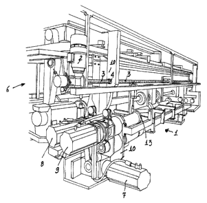
Figure 1 is a side perspect~.ve view
illustrating the paperboard sheet die-cutting device
according to the present invention, appl.=.ed to a
3l.ottiRg ItlaChine j
Figure 2 is a further detaa.~.ed side
pezspective view illustrating the paperboard sheet
die-cutting device according to the invention;
Figure 3 ilhzstrates a side view of the
die-cutting devices and clearly show the supporting
framework ~f said device, applied to a paperboard
sheet slotting machine;
Figure 4 shows the supp~rting framework of
the die-cutting devvce of the invention, which
framework ~.s driven by a worm screw engaging with a
female thread formed orl s. b~.sh applied to the
supporting framework.
CA 02418596 2003-02-10
l~D
~°3gure 4 further schematically shows cross-
b~.ade pairs, incluc~.inc~ cuttyng,~blades f~dr .perf4rming
two cross slots, with respect to be paperboard sh~:et
feeding or ad~tancing da,recti.v~., this figure further
showing a side tr~.mm5_ng knife, which i.s upward and
dawn~nrard operated through a fever by a pneumatic
piston;
Figure 5 is a top s~.de perspe~ct~.ve ~criew of
the above assembly, iaz which is shown the piston for
raising the trimming knife and the two-shaft assembly
a.ncluding two shafts each supporting a pair of cross
blades, for pez~forrning cross slots, with resQect to
the paperboard sheet feeding ar advancing direction;
Figure 6 slows a side front view of the
die-cut~.ing device accord~.ng to the inventiozl~
Figures 7, d3 as~d 9 show possible caperating
steps which caz~ be carried out on fl<at paperboard
sheets to be used for making packag3.ng boxesf
and
Figure 10 .illustrates a side view of a
modified embodiment of the die-cutting device
according to the inverztion.
DESCRIPTION OF THE PRE1F'ERRED EM800IME~TS
with reference to the number references of
the figuxes of the accompanying drawings, the
CA 02418596 2003-02-10
improved paperboard sheet die-cutting device
according to the present invention, vahich has been
generally indicated by the reference number l, is
provided for mounting at the. outlet o~ the paperboard
sheets 64 being processed by a paperboard sheet
slotting machine.
More spec~.f_i.cally, the die-cutt~.ng device
according to the invention is mounted on a supporting
framework 10, which .can be transversely driven with
respect to the long~.tud3nal feeding or advancing
direction of the paperboard sheet 60.
This movement, in particular, is cGntro3.led
by a gear-rnvtor unit 2, which rotatively drives a
worz~ screw ~ engaging with a female thread of a bush
4 applied to the supporting framework 1.0 of the die-
cutting dev~.ce 1.
As shown, said supporting trame~aork IO is
designed for sliding an cress slides 5 applied to the
slotting machine s to which the subject device is
coupled.
Alternatively, the die-cutting devise 7. can
comprise an independent bearing corastructir~n.
The devise 1 comprises brushless motor 7, 8
and 9.
A first of said motors drives a toothed
CA 02418596 2003-02-10
pulley 1~., thereon is entrained a drive belt 12,
controlled by a belt tension element l9 and a pair of
pulleys 2Q and 2I rigid with. shafts 35 axad 36.
~Che belt l~, in turn, rotatively dxives
said shafts 35 and ~6 thereon axe idly supported the
polyurethane rizzg elements 15 and 16 operating as
abutment elements for the cutting operation provided
by the cross blades 17 and 18 of the die-cutting
dsvice 1.
Said ring elements 1~ and 16 can be idly
rotatively dri~ren, so as to allow the m.~oss blades 17
and 18 to operate at different cutting positions,
therehy preventing the abutment rings 15 and 16 from
being quickly waxn.
The first brushless motor 7 rotatively
drives the bottom ring elements or rollers 15 and 16,
the operating speed of which is synchronized with the
outlet speed of the paperboard sheet to be processed.
Eaah of the other two brushless motor 8 and
9 drives the advancing or feeding moveanent of two
shafts 33 and 34 supporting a pair of cross blades I7
and ~.8, vrhich arE designed for performing two Cross
slots, with respect to the paperboard sheet feeding
direct3.on .
Alternatively, said two cross blades 17 and
CA 02418596 2003-02-10
18 can be replaced by a pre-shaped die-cutting unit,
having wood shell means beaxing~the contoured blades.
~n this connection, it is to be po~.nted out
that the die-cutting de~crices or ~ assemblies 1 e. z~tounted
on the slotting machine, are provided inn a r~urnber of
two.
More specifica3.~.y, they are znoun.ted or
coupled to the side portions of the slotting machine
frame.
In the exemplary embodiment shorn s.n figure
7, oils of the rollers inc2uding the cross knives or
blades, performs, at subsequent operating times, -the
first and third slotting operat~.on, _ a a:nd c, whereas
the other two knives, applied on the second. roller,
perform, at different times too, the second and
fourth cross s3.ots b and d.
Figure 8 shows a, further working example
'which can be carried out by using a pair of die-
cutting devices, in cooperati~an with a slotting
assembly longitudinally extending with respect to the
paperboard sheet feeding direction.
This figure, in particular, shows four
longitudinal cuts e, f, g, h perf:oxmed by a
longitudinal slotting assembly, and four cross cuts
i, l, m, n performed by two die-~cut.ting devices
CA 02418596 2003-02-10
according to the inventions
Thus, it i.s possible.~to automatically trim
or cut away the paperboard portions whack has been
shown, zn the draw~.rags by the dashed lines and
indicated by the reference nurrtbers 70, 71, '72 and 73.
Figure 9 shows another possible workixzg
example which can be carra.ed out bgr the di.e-cutting
device according to the ir~~rentzon.
lNfore specifically, t~ais figure Shows a,
paperboard sheet cut by two series of cross cuts o,
p, q, r and o', p', ci°~ r' and two series of
longitudinal cuts s, t., u, v'and s', t', a°, v'.
The cross cuts are provided. by cutting
blades of different lengths.
In part.icul,ar, two shorter blades, applied
on a supporting shaft, performs the outs p, p' and q,
q', whereas two othex Xonger blades perform the cross
cuts o, r and o~, r'~
The die-cutting d~avice 1 according to the
invention is moreover provided with a circular
trimming knife 13 which can be driven toward and away
with respect to the paperboard sheet.
This circular trimming knife 13 is driven
by pneur~ati.c piston. 31, designed fo:r verti.Gally
swinging, thxough a sh.~.ft ~0 a.nc1 a pfn 4:1, a lever 32
CA 02418596 2003-02-10
as
supporting the rotary shaft 50 of the tri,~n~zt.ing kni.fa
__ _.. . ..._.
13.
As is shown in figure 6, during its
trimming simple operation, the~knife 13 can be idly
ratatively driven about the shaft 5t3, the ~.~ris og
which is cross-wise direct8d with respect to the
paperboard sheet feeding direction.
It is further possible to u;se t3ze cross
blades 17 and ~.8 for crumbling the paperboard
material portion exceeding the rated siz~c.
The trimming blade 13 is rotatively driven
by the paperboard sheet 60Vfeeding movement, which
drives the counter-pres sing top roller !5 ~. xi.gad with
said I~cn~.fe 1.3
~'zgures 7, a and 9 show several operating
steps which can be carried out by thE~ diE-cutting
device according to the invention, i.e. a lot of die-
cuttiza.g operations pc~rforrned in a cross direction
with respeot to the paperboard sheet feed~.ng mavement
and further longitud~_nal trimming Qperatiozls ~thich
can be performed by the subject machine.
Figure 10 sho~rrs a modified embodiment of
the die-cutting device, designed for performing cross
cuts instead of cross slots.
In this case, the shafts 35 a;nd 36, which
CA 02418596 2003-02-10
32
are similar to those shown .iz~ figure 4, instead of
supporting the ring elements ~15 and . ~.6 and being
driven by the motor '7, support transversal blades 90
and are rotatively driven, ~ in a mecrianically
synchronized manner, together with the shafts 33
driven by the motors ~ and 9.
Also in this case, the paperboard sheet 60
is evenly driven lay the roller 52 and related idle
counter-pressing roller, coupled to the anotor 7.
While the die-cutting device according to
the present invention has been hereinabove
i7.3.ustrated with reference to a preferred embodiment
thereof, it should be apparent that it is susceptible
to several modifications and variations, all of which
will enter the scope of the invention.