Note: Descriptions are shown in the official language in which they were submitted.
CA 02418621 2003-02-06
WO 02/14035 PCT/AU01/01008
-1-
ELECTRIC POWER TOOL
This invention relates to electric power tools which are adapted for under
bench operation and particularly to a router for hand held and under bench
applications.
Routers are in the category of electric power tools having a motive power
within a housing with a tool holder for a cutting tool, in which the motive
power
for the tool holder and cutting tool are aligned along the longitudinal axis
of the
cutting tool. A router will generally have a base plate connected to the
housing
' by guide poles with the cutting tool extending through the plate. The tool
is
held by a tool holder which is difficult to access for tool changing in under
bench operation.
As almost all routers are principally designed for hand held use, the tool
holder is limited in its movement and is not designed to extend beyond the
opening in the base plate.
This limitation introduces a number of problems associated with the
operation of these electric power tools. The abovementioned restriction in the
movement of the tool holder reduces the ability to change the cutting tool
easily.
This is a particularly serious limitation if the router is to be used for
under bench
operation or an over-bench operation where the router is used in conjunction
with a guide structure.
Furthermore, as the tool holder is always between the housing and the
base plate access to the tool holder is restricted by the guide arms and the
base
plate. When the cutting tool in the tool holder is to be changed, the tool
holder
needs to be immobilised by depressing or holding an in built shaft lock or
using
a key with one hand while it is loosened using a key with the other hand. In
any
event, the cutting tool changing operation is a two-handed operation which is
made more difficult by the limited access to the tool holder.
It is an object of the present invention to provide an electric power tool
and particularly a router which overcomes at least one of the above
disadvantages.
CA 02418621 2003-02-06
WO 02/14035 PCT/AU01/01008
Accordingly, in one aspect, the invention provides an electric power tool
including a housing having a motive power therein, a tool holder coupled to
said
motive power for receiving a cutting tool and rotating said cutting tool about
a
longitudinal axis, a base plate having an opening through which said cutting
tool
extends to engage a work piece, said base plate being adjustably mounted to
said housing by guide arms, the extension of said cutting tool being varied by
adjusting the position of said base plate relative to said housing, said tool
holder
being able to extend through the opening in said base plate.
The abovementioned electric power tool, which is preferably a router, is
particularly adapted although not restricted to under bench use or for over
bench
use where the router is placed on a guide mechanism. By enabling the tool
holder to extend beyond the opening in the base plate access to the tool
holder
for tool changing is greatly improved. This is especially beneficial for under
bench use of the power tool.
In a preferred form of this aspect of the invention, the tool holder is
engageable with said base plate, and disengagement means is provided to
disengage the motive power prior to contact of the tool holder with the base
plate. The disengagement means is preferably a stop which is activated.
whenever the motive power is activated. Once the motive power is disengaged,
the stop may be deactivated to enable the housing and base plate to be brought
sufficiently close together to allow engagement of the tool holder with the
base
plate.
In accordance with a second aspect of the invention, there is provided an
electric power tool including a housing having a motive power therein, a tool
holder coupled to said motive power for receiving a cutting tool and rotating
said cutting tool about a longitudinal axis of said cutting tool, and a base
plate
having an opening through which said cutting tool extends to engage a work
piece, said base plate having means of engaging said tool holder only when the
motive power to the power tool is disengaged or off.
In a preferred form of this aspect of the invention, the power tool
includes a safety stop which prevents contact between said tool holder and
said ,
CA 02418621 2003-02-06
WO 02/14035 PCT/AU01/01008
-3-
base plate while the motive power is engaged. Once the motive power is
disengaged and the base plate and tool holder brought into contact, a locating
pin preferably provided in the base plate engages with a recess formed in the
tool holder. Once engaged, the locating pin immobilises the tool holder and
retains the tool holder in position until released.
The motive power to the power tool is preferably activated and
deactivated by a switching means including a slide cover and an on/off switch.
So that the motive power cannot be accidentally activated once switched off,
the
slide cover is spring loaded to engage with the switch to retain the switch in
the
off position. It is held back by the switch, against the spring, when the
switch
is in the on position.
Guide arms extend between the base plate and the housing to adjustably
control the relative position of the base plate to the housing. The guide arms
are
preferably received within sleeves formed in the housing, the housing being
provided with an adjustment means.
The slide cover of the switch means further includes a safety stop which
limits the progress of at least one of the guide arms within each respective
sleeve of the housing when the slide cover is held back in its retracted
position
by the switch in the on position. The guide arms are constructed so that the
tool
holder is not in contact with the base plate when at least one guide arm
contacts
the safety stop. The slide cover is spring loaded toward the. switch and is
held
back over the plunge posts when the switch is on.
The features, objects and advantages of the present invention become
more apparent from the following description of the preferred embodiment and
accompanying drawings in which:-
Figure 1 is a perspective view of an embodiment of the invention with
the rear of the housing removed,
Figures 2, 3 and 4 are side elevational views of the embodiment of Figure
1 illustrating the travel of the housing with respect to the base plate,
Figure 5 is a sectional view of the embodiment of Figure 4 with the rear
of the housing intact, and
CA 02418621 2003-02-06
WO 02/14035 PCT/AU01/01008
-4-
Figures 6-9 are perspective views of the embodiment of Figure 1
illustrating the operation of the safety switch as the housing approaches the
base
plate.
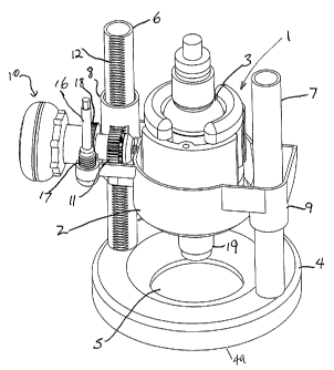
Referring to the drawings, an electric power tool 1 in accordance with the
invention, and embodied as a router, is shown to include a housing 2 having a
motive power 3 therein . In Figure 1 the rear of the housing 2 is removed to
show the motive power 3 which is an electric motor 1 which may be powered
by a portable power source such as a battery, or by mains power.
A base plate 4 is provided preferably having a flat base 4a so that the
router can be stably supported against a work piece or a table. The base plate
4
is provided with an opening 5 for the passage of a cutting tool, which in the
case
of the embodiment shown in Figure 1, is a router bit.
The position of the base plate 4 relative to the housing 2 is defined by
guide arms or posts 6, 7 which are received within a fixture 8, 9 on the
housing.
The adjustment of the housing 2 relative to the base plate 4 is performed by a
height adjustment mechanism 10 which preferably provides both coarse and fine
adjustments.
The height adjustment is performed by a sprocket 11 which engages teeth
12 on one of the guide arms 6. As best seen in Figure 5, the sprocket 11
rotates
about an axle 12 which is engageable with a coarse adjustment knob 13. The
coarse adjustment knob 13 is provided with a clutch mechanism which
facilitates engagement between the sprocket 11 and the coarse adjustment knob
13.
The clutch mechanism, which is a slidable sleeve 14 fitting over and
rotationally fixed relative to a mounting shaft 15 of the coarse adjustment
knob
which is engageable with the coarse adjustment knob by axial movement along
the mounting shaft 15. When the sleeve 15 engages with the coarse adjustment
knob 13, the relative position of the mounting shaft 15 and the coarse
adjustment knob is fixed until the sleeve is released, whereupon the sleeve
returns to its original position under the action of a spring bias.
CA 02418621 2003-02-06
WO 02/14035 PCT/AU01/01008
-5-
As the mounting shaft 15 is directly connected to the sprocket 11,
rotation of the knob when the sleeve 14 is engaged, rotates the sprocket 11
causing the housing to progress up or down the guide arm 6.
A fine adjustment knob (not shown) may be provided which engages
with teeth formed on the surface of mounting shaft 15. The fine adjustment
knob is mounted on a substantially vertical shaft 16 (shown in Figure 1)
having
a screw thread 17 which engages with the teeth 1 ~ on the mounting shaft 15.
Rotation of the fine adjustment knob and hence vertical shaft 16 causes small
rotational movements of the mounting shaft and hence the sprocket 11. These
movements are smaller than those caused by rotation of the coarse adjustment
knob 10.
The motive power 3 is coupled to a tool holder 19 for a cutting tool. The
cutting tool which preferably extends coaxially with the motive power 3
extends
through opening 5 in base plate 4 to contact a work piece (not shown).
As illustrated in Figures 2-4, the adjustment mechanism allows the
housing 2 to be progressed towards the base plate. As the working depth of the
cutting tool in the tool holder 19 is defined by the extension of the cutting
tool
beyond the base plate 4,, as shown in Figure 4, the tool holder 19 extends
through the base plate thereby maximising the cutting depth. Additionally, by
having the tool holder extending through the opening 5 in the base plate 4,
the
tool embodying the invention is also able to provide greater access to the
tool
holder 19 for changing the cutting tool.
While having a tool holder 19 which is able to extend through the base
plate 4 provides advantages over the prior art, the arrangement also
introduces
safety and operation risks if the motive power is still activated when the
tool
holder 19 extends beyond the base of the base plate 4.
Hence, it has been found to be advantageous to provide an arrangement
which prevents the tool holder from extending the beyond the base plate while
the motive power is activated. The operation of the safety mechanism of the
invention is illustrated in Figures 6 to 9.
CA 02418621 2003-02-06
WO 02/14035 PCT/AU01/01008
-6-
As the housing 2 is moved closer to the base plate 4, the guide arm 6
moves within and extends above its sleeve mounting 8. Fixtures 24 are
provided on housing 2 to define the limit of travel of the guide arm 6 along
the
side of housing 2 and are positioned to correspond to the position of the
guide
arms when the housing 2 is at its lowest position relative to the base plate
4.
The safety mechanism includes an on/off switch 20 with a switch block
21. The switch block 21 is provided with grooves (not shown) to receive a
switch plate 22 in sliding engagement. The switch plate 22 covers and prevents
access to switch 20 only when the switch is in the off position (as shown in
Figure 9). The switch plate 22 moves between a position which covers the
switch 20 and one which allows access to the switch. Switch plate 22 is
further
provided with a stop 23 which extends between the switch plate 22 and housing
2. When the switch plate is not covering switch 20, stop 23 extends across the
path of guide arm 6 as the housing is moved towards the base plate. When the
switch plate 22 is in this position, the switch 20 can be either on or off
corresponding to the motive power being activated or deactivated respectively.
While the switch plate is not covering switch 20, it is not possible for
guide arms 6 to travel to their limit of travel. Hence, housing 2 is
restricted
from descending to its lowermost position relative to base plate 4. By
selectively designing the position of the fixtures 24 and the length of guide
arms
6, the tool holder 19 can be prevented from extending through the base plate 4
without the switch being deactivated as shown in Figure 7.
Once the switch 20 to motive power 3 is switched off, switch cover 22 is
spring loaded to cover the switch. Movement of the switch cover removes the
stop 23 from the path of the guide arm 6 allowing housing 2 to be moved closer
to the base plate (Figure 9).
With switch cover 22 covering the switch 20, the motive power 3 is
prevented from being activated.
Another difficulty with the routers currently on the market is the access
to the tool holder 19 during tool changing operations. While a tool holder 19
which extends through the base plate provides easier access to the engagement
CA 02418621 2003-02-06
WO 02/14035 PCT/AU01/01008
_7_
mechanism of the tool holder, the changing operation is nevertheless a two-
handed process. By immobilising the tool holder 19 when it extends through
the base plate 4, the tool changing operation can become a single-handed
operation from above the router table.
Referring to Figure 5, an embodiment of the router in accordance with
the second aspect of the invention is shown. The tool holder 19 extends
through
opening 5 in the base plate 4 and engages with a releasable latching
mechanism.
The latching mechanism comprises an external plunger 25 with an inclined
face, a pin 24 for engagement with a recess 26 in the tool holder 19 and two
springs (not shown), all contained within the lower housing 2 As the router is
fully plunged, 25 engages the inclined face inside the base 4 and pushes the
pin
24 forward by means of a spring (not shown) between the inner face of 25 and
the annular fin around the mid point of 24. There is a second, weaker spring
on
the other side of the annular fin on 24 which is used to return the mechanism
when the router is raised to disengage the inclined faces of 4 and 25.
To operate the latching mechanism, the housing 2 is positioned in its
lowermost position relative to the base plate 4. Tn this position, the tool
holder
19 extends through the base plate 4, and the positioning of the housing 2
activates the latching mechanism releasing latch pin 24 which is forced
towards
the tool holder 19 under the action of a spring bias (not shown). The tool
holder
19 may then be rotated manually until the pin locates within the recess 26 in
the
. tool holder 19. Once the pin 24 engages with the tool holder, the tool
holder 19
is effectively immobilised until the latching mechanism is disengaged. In this
position, the tool holder 19 which may be a keyed or keyless collet, may be
loosened and/or tightened as a single-handed operation to facilitate changing
of
the cutting tool (not shown) in the tool holder 19.
To disengage the latching mechanism, the router is raised, removing the
inclined face on the base 4 from contact with the inclined face on 25, the pin
24
is then free to be retracted by the weaker inner spring (not shown) between
the
annular fin on 24 and the housing 2. Comment; it may not have been clear that
the latch mechanism is carried on the housing 2, not built into the base 4.
CA 02418621 2003-02-06
WO 02/14035 PCT/AU01/01008
_$_
It will be appreciated from the above description that the switch cover 22
prevents the motive power 3 being activated which the latching mechanism is
activated thereby prevent damage to the tool. Similarly, the latching
mechanism
can not be activated while the switch is on since the pin 24 is unable to
engage
the recess 26 as described above.