Note: Descriptions are shown in the official language in which they were submitted.
CA 02418843 2003-02-10
WO 02/14607 PCT/US01/25249
RAIL ANCHORING SPIKE
TECHNICAL FIELD
This invention relates to fasteners for attaching metal to wood, and more
particularly to an improved railroad spike for attaching a metal rail to a
wooden tie.
BACKGROUND
It is common in constructing tracks for trains to provide a rail or rails
supported
on cross ties formed of wood. The rails are commonly made of a metal such as
steel, and
are generally provided with mounting flanges. The mounting flanges are adapted
to rest
on metallic bearing plates, commonly referred to as tie plates or fishplates.
The fishplates
in turn rest on the wooden ties. It is common to employ spikes (i.e. cut
spikes) for
securing rails to ties. In the usual case, a spike is inserted in an opening
or cavity in the
fishplate and the spike shank is driven into the tie. The head of the spike is
generally
adapted to engage with the flange of the rail, thereby securing the rail to
the tie.
Alternatively, the fishplate may be equipped with a metal clip or boss that
engages to the
flange of the rail, and the head of the spike is adapted to engage with the
fishplate to
secure the rail to the tie.
After being in service for a short period of time, the ordinary spike often
works
loose from the tie due to the working action that occurs as the rail deflects
under the load
of passing trains and due to expansion and contraction of the wood fibers of
the tie due to
temperature, humidity and other environmental changes. Such loosening of the
spike can
necessitate replacement of the spike or other parts of the track assembly.
Attempts to
secure or anchor a spike by providing the shank with burrs, barbs, serrations
or similar
rough features adapted to engage with the wooden ties generally have proved
unsatisfactory. Such spikes can be difficult to drive into a tie using manual
or automated
impact spike-driving methods. The rough feature may also chew or tear the wood
fibers
of the tie during installation, thereby causing damage to the tie.
In addition, after such spikes have been in service an appreciable length of
time,
they will have a tendency to work in the hole established in the tie by the
spike shank.
-1-
CA 02418843 2003-02-10
WO 02/14607 PCT/US01/25249
Working of the spike acts to enlarge the hole surrounding the shank and to
damage the
surrounding wood fibers, causing the spike to loosen over time. The enlarged
hole may
also permit water and other chemicals to enter the hole surrounding the spike
shank,
thereby further weakening the spike or the surrounding wood fibers. Removal of
the
spike usually causes additional damage to the tie; therefore, spike removal
often requires
replacement of the entire tie in order to ensure that the replacement spike
will anchor the
rail to the tie with sufficient holding power.
Spikes have been adapted with threaded shanks that can be screwed into the
wooden tie. However, such spikes are difficult to install using manual or
automated
impact driving methods. Furthermore, such spikes generally require a pre-
drilled hole in
the tie to facilitate installation using rotary spike driving methods.
Threaded spikes are
also known to work loose under the load of passing trains. In an attempt to
reduce
working of spikes under load, attempts have been made to equip spikes with
tabs or
uniquely shaped shanks adapted to engage witli the cavity of a fishplate,
thereby locking
the spike into engagement with the fishplate, reducing the tendency of the
spike to work
loose and damage the tie. Such spikes, however, are extremely difficult to
install using
automated impact spike-driving methods. In addition, such spikes can generally
be used
only in conjunction with a fishplate, and are extremely difficult to remove
once locked
into engagement with the fishplate.
The art continually searches for improved spikes suitable for use in securing
a
metal rail to a wooden tie. In particular, the art continues to search for
spikes that exhibit
a reduced tendency to work under the load of passing trains, for spikes that
are readily
removed and re-installed without requiring replacement of the tie, and for
spikes that are
capable of installation using automated spike-driving methods.
SUMMARY
This invention relates generally to an improved fastener for attaching metal
to
wood. More specifically, in one aspect, the invention features an improved
railroad spike
for attaching a metal rail to a wooden tie. The improved spike is well-suited
for use with
automated spike-driving methods, and is adapted to engage with the wooden tie
to
prevent or reduce loosening of the spike due to working of the spike under the
load of a
-2-
CA 02418843 2008-06-11
passing train, or due to expansion or contraction of the wood fibers in
response to changing
environmental conditions.
Accordingly, the present invention provides a metal to wood fastening spike,
comprising: a head having an annular flange; a stand-off extending axially
from said flange; a
plurality of flutes extending axially from said stand-off, said flutes being
adapted to engage
wood; said stand-off having a length adapted to ensure that said flutes are at
least partially
embedded in wood when said spike is used to fasten metal to wood; and a shank
extending
axially from said flutes to form a tapered tip, said shank further comprising
a plurality of
helical, generally parallel threads extending over at least a portion of said
shank, running
from said flutes to said tip.
In one embodiment, the head of the spike comprises a generally polygonal
projecting
tool grip extending axially from the flange on the side opposite to the
threaded shank. The
tool grip is adapted for engagement with a wrench to enable rotary driving of
the spike into
the tie or removal of the spike using a rotary motion imparted to the tool
grip.
In a variation of this embodiment, the spike head is adapted for use with
impact spike-
driving methods. The head of the spike is preferably hemispherical or dome
shaped and is
adapted to for use with manual or automated impact spike-driving methods.
Preferably, the
hemispherical head is adapted to deform slightly under impact driving, thereby
preventing
damage to the tool grip.
In another embodiment, the threads are adapted to facilitate driving of the
spike into
the wooden tie using impact or rotary spike-driving methods, and to permit
easy removal of
the spike using rotary spike removal methods.
In a preferred variation of this embodiment, the threaded shank is adapted to
permit
driving of the spike into the tie using an impact driving method, and to
permit easy removal
of the spike using a wrench or other rotary spike removal method. The threads
are adapted to
cause rotation of the spike into the tie during installation using automated
or manual impact
spike-driving methods. The threads are preferably adapted to screw the spike
threads into the
wooden tie when a force is applied to the head of the spike in a direction
generally towards
the spike tip.
In a preferred embodiment, the improved spike is used with a metal tie plate
or
fishplate to secure the rail to the tie. In this embodiment, the length of the
stand-off must be
adapted to ensure that the flutes are at least partially engaged with the
wooden tie when the
-3-
CA 02418843 2008-06-11
spike is driven into the tie. The tie plate or fishplate preferably comprises
a metal boss or an
elastic fastener that is adapted to engage with the flange of the rail,
thereby securing the rail
to the tie when the spike is driven into the tie.
In another aspect, the invention features a railroad track assembly comprising
a metal
rail, a wooden tie, a metal tie plate adapted to engage said rail, and a spike
driven into said
tie, said spike adapted to fasten said tie plate and said rail to said tie,
said spike further
comprising: a head having an annular flange; a stand-off extending axially
from said flange; a
plurality of flutes extending axially from said stand-off, said flutes being
adapted to engage
wood; said stand-off having a length adapted to ensure that said flutes are at
least partially
embedded in said tie when said spike is used to fasten said tie plate to said
tie; and a shank
extending axially from said flutes to form a tapered tip, said shank further
comprising a
plurality of helical, generally parallel threads extending over at least a
portion of said shank,
running from said flutes to said tip.
In still another aspect, the invention features a method of using a railroad
spike,
comprising: providing a railroad spike comprising a head having an annular
flange, a standoff
extending axially from said flange, a plurality of flutes extending axially
from said stand-off,
and a shank extending axially from said flutes to form a tapered tip, said
shank further
comprising a plurality of helical, generally parallel threads extending over
at least a portion
of said shank running from said flutes to said tip; providing a wooden tie, a
metal rail, and a
fishplate adapted to engage with said rail and said tie; and driving said
spike into said tie until
said flutes are at least partially embedded in said tie, and said fishplate is
engaged with said
rail.
In a preferred variation of this embodiment, an automated spike-driving method
is
used to drive the spike into the tie, thereby securing a metal rail to the
wooden tie. Preferably,
an automated impact spike-driving method is employed. In an alternative
embodiment, a
manual spike driving apparatus is used to drive the improved spike into the
tie.
The details of one or more embodiments of the invention are set forth in the
accompanying drawings and the description below. Other features, objects, and
advantages of
the invention will be apparent from the description and drawings, and from the
claims.
-4-
CA 02418843 2003-02-10
WO 02/14607 PCT/US01/25249
DESCRIPTION OF DRAWINGS
Figure 1 is a perspective view of a typical metal to wood fastening
application
embodying the present invention.
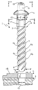
Figure 2 is a side elevation view of a spike embodying the present invention.
Figure 3 is top plan view of a spike embodying the present invention.
Figure 4 is a fragmentary, transverse cross-sectional view of the shank
portion of a
spike embodying the present invention.
Figure 5 is a fragmentary, transverse axial view of a spike embodying the
present
invention.
Like reference symbols in the various drawings indicate like elements.
DETAILED DESCRIPTION
Figure 1 illustrates a perspective view of a typical metal to wood fastening
application embodying the present invention. Figure 1 illustrates the
fastening of a metal
rail 18 to a wooden tie 9 using the improved spike 1 of the present invention.
In the
illustrated embodiment, a metal tie plate or fishplate 12 comprising a boss or
elastic
fastener 16 engages with the flange 14 of rail 18. A plurality of spikes 1 are
inserted into
cavities in the fishplate 12, to secure the fishplate 12 and the rail 18 to
the tie 9.
Figure 2 illustrates a side elevation view of the improved spike embodying the
present invention. The spike has a head 10 having an annular flange 11, a
stand-off 15
extending axially from the flange 11, a plurality of flutes 17 extending
axially from the
stand-off 15, a shank 5 extending axially from the flutes to form a tapered
tip 8, and a
plurality of pitched, helical, generally parallel threads 6 extending over at
least a portion
of the shank, iluv.iing from the flutes 17 to the tip 8. The threads have an
upper thread
surface 6b, and a lower thread surface 6a.
In one embodiment of the invention, depicted in Figure 2 and Figure 3, the
head
10 comprises a projecting polygonal tool grip extending axially from the
flange on the
side opposite to the threaded shank. Although the shape of the tool grip is
not critical, it
is generally adapted for engagement by a wrench to enable rotary driving of
the spike into
the tie or removal of the spike using a rotary motion imparted to the tool
grip. It will be
understood by those skilled in the art that a variety of equivalent structures
may be
-5-
CA 02418843 2003-02-10
WO 02/14607 PCT/US01/25249
substituted for the projecting polygonal tool grip without departing from the
invention.
Thus, for example, the head of the spike may comprise a generally polygonal
recessed
tool socket positioned on the flange on the side opposite to the threaded
shank, wherein
the recessed socket is preferably adapted for engagement with a socket wrench
or socket
driver to enable rotary driving of the spike into the tie or removal of the
spike using a
rotary motion imparted to the socket.
As shown in Figure 2 and Figure 3, a hemispherical head 13 is preferably
provided to permit driving of the spike into the tie using impact spike
driving methods
that apply a force to the head of the spike in the general direction of the
spike tip. The
hemispherical head 13 is preferably deformable by virtue of the material used
to make the
head, and is adapted to deform slightly under impact driving, thereby
preventing damage
to the tool grip that could prevent removal of the spike using a wrench.
Figure 4 shows a cross-sectional top view of the improved spike illustrating
use of
a substantially cylindrical shank defined by the flat lands 7, and the upper
thread surface
6b of the pitched helical threads. Figure 4 also shows a plurality of flutes
17. The flutes
extend radially outward from the shank, and extend axially between the stand-
off and the
point at which the threads terminate on the shank. The position of a flute on
the shank
preferably corresponds to the termination point of a thread. In other words,
the lower end
of an individual flute (i.e. the flute end furthest from the stand-off) marks
the upper
termination point of an individual thread (i.e. the thread end fixrthest from
the tip).
Because the flutes extend outward and away from the center of the shank, the
flutes are adapted to resist removal of the spike by engaging with wood fibers
once the
spike is driven into the tie. Thus, when driving the spike into the tie, the
leading edge 17b
of each flute compresses and deforms the wood fibers of the tie. This permits
the spike to
be readily driven into the tie. Once driving is completed, however, the wood
fibers of the
tie relax and recover by filling in voids adjacent to the flutes that were
created by the
driving step. The trailing edge 17a of each flute thus acts to hold the spike
or lock the
spike into the tie with a force sufficient to resist loosening (i.e. turning
out) of the spike
due to working under load or due to the elements.
As shown in Figure 5, the helical threads preferably have an upper thread
surface
6b which defines an obtuse pitch angle relative to the nearest adjacent land 7
which is
-6-
CA 02418843 2003-02-10
WO 02/14607 PCT/US01/25249
substantially closer to ninety degrees than the pitch angle defined between
the lower
thread surface 6a and the nearest adjacent land 7. Because this preferred
thread design
allows the spike 1 to freely screw into the tie 9 when a force is applied to
the head (i.e. the
spike is driven), such a thread design is particularly well suited for use
with automated
spike driving equipment. Most preferred is automated impact spike driving
equipment
that drives the spike by applying a force to the spike head substantially in
the direction of
the tip of the shank. Suitable automated spike driving equipment includes the
Nordco
Model 99C spike driver (Nordco, Inc., Milwaukee, Wisconsin), Fairmont Tamper
Model
W96 (Fairmont Tamper, a Division of Harsco Track Technologies, Company, West
Columbia, South Carolina) or the like.
In addition, the preferred thread design allows the spike 1 to be readily
driven
using hand operated impact spike driving equipment such as hammers, sledges,
mauls, or
power-driven/hand operated spike drivers such as the Ingersol Rand Spike
Driver Model
MX60, (Ingersol Rand, Inc.), Ingersol Rand Spike Driver Model MX 90 (Ingersol
Rand,
Inc.), or the like.
Preferably, the pitched helical threads 6 are adapted to permit driving of the
spike
1 into the tie 9 using a generally clockwise rotary motion applied to the tool
grip, and to
permit removal of the spike 1 from the tie 9 using a generally counter-
clockwise rotary
motion applied to the tool grip. Both clockwise and counterclockwise
directions refer to
the rotational direction of the tool grip when viewing the spike from the side
of the flange
opposite to the shank.
Alternatively, the threads 6 are adapted to permit driving of the spike 1 into
the tie
9 using a generally counter-clockwise rotary motion applied to the tool grip,
and to permit
removal of the spike 1 from the tie 9 using a generally clockwise rotary
motion applied to
the tool grip.
The improved spike is generally used with a metal tie plate or fishplate 12 to
secure the rail 18 to the tie 9. If a fishplate is used, the fishplate
preferably comprises a
metal boss or elastic fastener 16 adapted to engage _with the flange 14 of the
rail, and a
cavity into which the shank of the spike may be inserted to pennit driving of
the spike
into the tie. As shown in Fig. 1, the rail flange 14 preferably rests on the
tie plate or
fishplate 12, and the tie plate or fishplate 12 preferably rests on the wooden
tie 9.
-7-
CA 02418843 2003-02-10
WO 02/14607 PCT/US01/25249
Figure 2 illustrates the use of the inventive spike 1 in combination with a
metal
fishplate 12 having a cavity 2, and a wooden tie 9. Preferably, the tie 9 also
has a cavity
13 to accommodate the shank 5 of the inventive spike. Preferably, the stand-
off 15, the
threaded shank 5, the fishplate cavity 2 and the tie cavity 13 are all
substantially
cylindrical. The fishplate cavity 2 has a diameter A greater than or equal to
the diameter
E of the stand-off 15, and preferably has a diameter A greater than or equal
to the
diameter F of the threaded shank 5. In a preferred embodiment, a substantially
cylindrical
cavity 13 having a diameter B is fonned in the tie 9 before inserting the tip
8 of the spike
1. In this preferred embodiment, the diameter B of cavity 13 is less than the
diameter F of
the threaded shank.
It will be understood by those skilled in the art that the diameter and
overall length
of the spike are not critical, and may be varied according to the dimensions
of the tie and
tie plate or fishplate. Even though the overall length of the spike is not
critical and may
be any suitable length, this length is generally in the range of 15-25 cm.
However, the
length D of the stand-off 15 must be adapted to ensure that the flutes 17 are
at least
partially engaged with the wooden tie 9 when the spike 1 is driven into the
tie 9. This
ensures that the flutes 17 are locked into engagement with the wooden tie 9
with a force
sufficient to prevent or reduce the tendency for the spike to loosen under the
load of
passing railroad locomotives and rolling stock (not shown). Preferably, the
length D of
the stand-off 15 is at least as long as the length C of the cavity in the
fishplate 12, thereby
ensuring that the flutes 17 are f-ully-engaged with the wooden tie. Most
preferably, the
length of the stand-off is between about 2 cm to 5 cm.
Notwithstanding the improvements embodied in the present invention, it will be
understood by those skilled in the art that it may be necessary to replace
components of a
railroad track assembly due to damage or wear. Such replacement will generally
require
the removal of one or more spikes. It is understood that some damage to the
wooden tie
may occur due to repeated removal or installation of improved spikes of the
present
invention. An aspect of the present invention therefore involves removal of an
improved
spike having a first stand-off length, and replacement with an improved spike
having a
second, longer stand-off length, in order to ensure that the flutes of the
replacement spike
engage wood fibers that are substantially undamaged by the flutes of the
removed spike.
-8-
CA 02418843 2003-02-10
WO 02/14607 PCT/US01/25249
Preferably, the spike comprises a metal. Although the spike may be made of any
number of metals or metal alloys, ferrous metals such iron or steel are
preferred. Ferrous
metals are preferred for use with an automated spike driving apparatus, since
magnetic
forces may then be used to hold the spike in operational engagement with the
driving
device.
Another aspect of this invention provides an improved railroad track assembly.
The assembly comprises a metal rail, a wooden tie, a metal tie plate adapted
to engage the
rail, and an improved spike of the present invention. The improved spike is
described in
the previous detailed description of the invention and in Figures 1-5.
In an embodiment of this improved track assembly, the improved spike is driven
into a wooden tie to secure a metal rail and a metal tie plate to the tie. The
tie plate is
adapted to engage the rail at the rail flange. The improved spike comprises a
head having
an annular flange, a stand-off extending axially from the flange, a plurality
of flutes
extending axially from the stand-off, and a shank extending axially from the
flutes to
form a tapered tip. The flutes are adapted to engage the wooden tie. The stand-
off has a
length adapted to ensure that the flutes are at least partially embedded in
the tie when the
spike is used to fasten the tie plate and the rail to the tie.
In a preferred variation of this embodiment, the shank further comprises a
plurality of helical, generally parallel threads extending over at least a
portion of the
shank, running from the flutes to the tip. In one variation of this preferred
embodiment,
the threads are adapted to permit driving of the spike into the tie using an
impact driving
method, and to permit easy removal of the spike using a wrench or other rotary
spike
removal method. The threads are generally parallel, helical threads extending
from the
flutes over at least a portion of the shank in the direction of the tip. The
threads are
adapted to cause rotation of the spike into the tie during installation using
automated or
manual impact spike-driving methods. In other words, the helical threads are
preferably
adapted to screw the spike threads into the wooden tie when a force is applied
to the head
of the spike in a direction generally towards the spike tip.
In another variation of this preferred embodiment, the spike head is adapted
for
use with impact spike-driving methods. The head of the spike is preferably
hemispherical
or dome shaped and is adapted to for use with manual or automated impact spike-
driving
-9-
CA 02418843 2003-02-10
WO 02/14607 PCT/US01/25249
methods. Preferably, the hemispherical head is adapted to deform slightly
under impact
driving, thereby preventing damage to the tool grip.
The present invention also provides a method of using an improved railroad
spike
to secure a metal rail and a metal tie plate to a wooden tie. The improved
spike is
described in the preceding detailed description of the invention and in
Figures 1-5. The
improved method comprises the step of driving the improved spike into the tie
to secure
the rail and the tie plate to the tie. The tie plate is adapted to engage the
rail at the rail
flange. The tie plate preferably comprises a metal boss or elastic fastener
(i.e. an e-clip)
that engages the rail flange when the improved spike of the present invention
is driven
into the tie, thereby securing the tie plate and the rail to the tie.
In a preferred embodiment, the tie plate comprises a cavity into which the tip
of
the spike shank is inserted before the spike is driven into the tie. The
improved spike of
the present invention is preferably driven into the tie until the spike flange
engages with
the tie plate and the metal flutes of the spike at least partially engage the
wood of the tie.
In the usual case, a hole or cavity (i.e. a pilot hole) is bored into the
wooden tie before the
spike tip is inserted into the tie plate cavity and the spike is driven into
the hole or cavity
of the tie. Preferably, the hole or cavity bored in the wooden tie has a
diameter smaller
than the diameter of the shank of the improved spike.
In a preferred embodiment, a driving device is used to drive the spike into
the tie,
thereby securing the metal rail to the wooden tie. Generally, the driving
device may be
either an impact driver, such as a hammer, sledge, or maul; or a rotary
driver, such as an
open-end wrench, box end wrench, socket wrench, or socket driver. Preferably,
an
automated impact spike-driving method is employed.
Other embodiments of the invention are within the scope of the following
claims.
1Q